Transcription
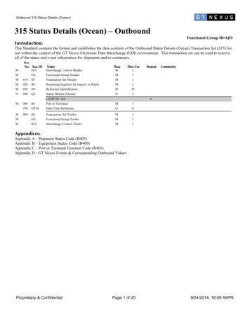
IMPORTANT SAFETY INSTRUCTIONSSAVE THESE INSTRUCTIONSEUROPEAN USERS400V 50Hz SUPPLY DETAILS AREINCLUDED WITH ELECTRICALCONTROL BOX. DISREGARD SUPPLYWIRING DETAILS IN THIS MANUALPLEASE READ THE ENTIRE CONTENTS OF THIS MANUAL PRIOR TOINSTALLATION AND OPERATION. BY PROCEEDING WITH LIFT INSTALLATIONAND OPERATION YOU AGREE THAT YOU FULLY UNDERSTAND THEFULL CONTENTS OF THIS MANUAL. FORWARD THIS MANUAL TO ALLOPERATORS. FAILURE TO OPERATE THIS EQUIPMENT AS DIRECTED MAYCAUSE INJURY OR DEATH.Rev. C1 – August 2017Manual P/N 5900951INSTALLATION AND OPERATION MANUAL10,000 LB / 4,536 KG CAPACITYSURFACE MOUNTED TWO-POST LIFTSMODELS: 168XPR-10AS-168-LPORIGINAL INSTRUCTIONS INENGLISH LANGUAGESymmetricalmodel shown.RECEIVINGThe shipment should be thoroughly inspected as soon as itis received. The signed Bill of Lading is acknowledgementby the shipping carrier as receipt of this product as listedin your invoice as being in a good condition of shipment. Ifany of these goods listed on this Bill of Lading are missingor damaged, do not accept goods until the shipping carriermakes a notation on the freight bill of the missing ordamaged goods. Do this for your own protection.BE SAFEYour new lift was designed and built with safety in mind.However, your overall safety can be increased with propertraining and thoughtful operation on the part of the operator.DO NOT operate or repair this equipment without readingthis manual and the important safety instructions showninside. Keep this operation manual near the lift at all times.Make sure that ALL USERS read and understand thismanual.1645 Lemonwood Dr.Santa Paula, CA. 93060, USAToll Free 1-800-253-2363Tel: 1-805-933-9970Fax: 1-805-933-9160www.bendpak.com1
10,000 LB / 4,536 KG CAPACITY SURFACE MOUNTEDTWO-POST AUTO LIFTSThis instruction manual has been prepared especially for you.Your new lift is the product of over 40 years of continuous research, testing, and development;it is the most technically advanced lift on the market today.READ THIS ENTIRE MANUAL BEFORE INSTALLATION & OPERATION BEGINS!Record here the lift and power unit information that is located on theserial number data plates on the lift and on the power unit.Power Unit Model #Power Unit Date Of Mfg.Power Unit Serial #Max Operating Pressure2,650 PSIThis information is required whencalling for parts or warranty issues.Product WarrantyOur comprehensive product warranty means more than a commitment to you; it’s also a commitment to the value of yournew BendPak lift. For full warranty details and to register your new lift contact your nearest BendPak dealer or visit:www.bendpak.com/support/warranty/What is not covered by your warranty: Any failure that results from purchaser’s abuse, neglect, or failure to operate, maintain, or service the product inaccordance with instructions provided in the supplied owner’s manual(s). Any damage caused by overloading the lift beyond its rated capacity. Items or service normally required to maintain the product; for example, lubricants, oil, and so on. Items considered general wear parts such as rubber pads, lifting cables, and so on unless wear or failure is a directresult of manufacturer defect due to material and/or workmanship. Any component damaged in shipment or any failure caused by installing or operating the lift under conditions not inaccordance with installation and operation guidelines or damaged by contact with tools or surroundings. Motor or pump failure caused by rain, excessive humidity, corrosive environments, or other contaminants. Rusted components due to improper maintenance or corrosive environments. Cosmetic defects that do not interfere with product functionality. Damage due to incorrect voltage or improper wiring. Any incidental, indirect, or consequential loss, damage, or expense that may result from any defect, failure, or malfunction of the BendPak, Inc. product.All electrical components (excluding power unit) are guaranteed for one year against defects in workmanship and/ormaterials when the lift is installed and used according to specifications.NOTE:Every effort has been taken to ensure complete and accurate instructions have been included in this manual, however,possible product updates, revisions and or changes may have occurred since this printing. BendPak Ranger reservesthe right to change specifications without incurring any obligation for equipment previously or subsequently sold.Not responsible for typographical errors.2
IMPORTANT NOTICEOWNER’S RESPONSIBILITYDo not attempt to install this lift if you have never beentrained on basic automotive lift installation procedures.Never attempt to lift components without proper liftingtools such as forklift or cranes. Stay clear of any movingparts that can fall and cause injury. These instructionsmust be followed to insure proper installation andoperation of your lift. Failure to comply with theseinstructions can result in serious bodily harm and voidproduct warranty. Manufacturer will assume no liability forloss or damage of any kind, expressed or impliedresulting from improper installation or use of this product.To maintain the lift and user safety, the responsibility ofthe owner is to read and follow these instructions:ttttPLEASE READ ENTIRE MANUALPRIOR TO INSTALLATIONttDEFINITIONS OFHAZARD LEVELS ttIdentify the hazard levels used in this manual with thefollowing definitions and signal words:tFollow all installation and operation instructions.Make sure installation conforms to all applicable Local,State, and Federal Codes, Rules, and Regulations;such as State and Federal OSHA Regulations andElectrical Codes.Carefully check the lift for correct initial function.Read and follow the safety instructions. Keep themreadily available for machine operators.Make certain all operators are properly trained, knowhow to safely and correctly operate the unit, and areproperly supervised.Allow unit operation only with all parts in place andoperating safely.Carefully inspect the unit on a regular basis andperform all maintenance as required.Service and maintain the unit only with authorized orapproved replacement parts.Keep all instructions permanently with the unit andall decals on the unit clean and visible.BEFORE YOU BEGINReceiving:The shipment should be thoroughly inspected as soon as itis received. The signed bill of lading is acknowledgement bythe carrier of receipt in good condition of shipment coveredby your invoice. If any of the goods called for on this bill oflading are shorted or damaged, do not accept them until thecarrier makes a notation on the freight bill of the shorted ordamaged goods. Do this for your own protection.Watch for this symbol: It Means: Immediate hazardswhich will result in severe personal injury or death.NOTIFY THE CARRIER AT ONCE if any hidden loss ordamage is discovered after receipt and request the carrierto make an inspection. If the carrier will not do so, preparea signed statement to the effect that you have notified thecarrier (on a specific date) and that the carrier has failed tocomply with your request.Watch for this symbol: It Means: Hazards or unsafepractices which could result in severe personalinjury or death.IT IS DIFFICULT TO COLLECT FOR LOSS OR DAMAGEAFTER YOU HAVE GIVEN THE CARRIER A CLEARRECEIPT. File your claim with the carrier promptly. Supportyour claim with copies of the bill of lading, freight bill,invoice, and photographs, if available. Our willingness toassist in helping you process your claim does not makeBendPak responsible for collection of claims orreplacement of lost or damaged materials.Watch for this symbol. It Means: Hazards or unsafepractices which may result in minor personal injury,product or property damage.3
TABLE OF CONTENTSWarranty / Serial Number Information . . . . . . . . . . . . . . . . . . . . . . . . . . . . . . . . . . . . . . . . . . . . . . . . . . . . . . . . . . . . . . 2Definitions of Hazard Levels . . . . . . . . . . . . . . . . . . . . . . . . . . . . . . . . . . . . . . . . . . . . . . . . . . . . . . . . . . . . . . . . . . . . . 3Owner’s Responsibility . . . . . . . . . . . . . . . . . . . . . . . . . . . . . . . . . . . . . . . . . . . . . . . . . . . . . . . . . . . . . . . . . . . . . . . . 3Before You Begin . . . . . . . . . . . . . . . . . . . . . . . . . . . . . . . . . . . . . . . . . . . . . . . . . . . . . . . . . . . . . . . . . . . . . . . . . . . . . 3Installer/Operator Agreement/ Protective Equipment . . . . . . . . . . . . . . . . . . . . . . . . . . . . . . . . . . . . . . . . . . . . . . . . . 5Introduction . . . . . . . . . . . . . . . . . . . . . . . . . . . . . . . . . . . . . . . . . . . . . . . . . . . . . . . . . . . . . . . . . . . . . . . . . . . . . . . . . . 6Safety / Warning Instructions . . . . . . . . . . . . . . . . . . . . . . . . . . . . . . . . . . . . . . . . . . . . . . . . . . . . . . . . . . . . . . . . . . . . . 6Tools Required . . . . . . . . . . . . . . . . . . . . . . . . . . . . . . . . . . . . . . . . . . . . . . . . . . . . . . . . . . . . . . . . . . . . . . . . . . . . . . . 7Step 1 / Selecting Site . . . . . . . . . . . . . . . . . . . . . . . . . . . . . . . . . . . . . . . . . . . . . . . . . . . . . . . . . . . . . . . . . . . . . . . . . . 7Step 2 / Floor Requirements . . . . . . . . . . . . . . . . . . . . . . . . . . . . . . . . . . . . . . . . . . . . . . . . . . . . . . . . . . . . . . . . . . . 7Concrete Specifications . . . . . . . . . . . . . . . . . . . . . . . . . . . . . . . . . . . . . . . . . . . . . . . . . . . . . . . . . . . . . . . . . . . . . . 7Assembly View / Description of Parts . . . . . . . . . . . . . . . . . . . . . . . . . . . . . . . . . . . . . . . . . . . . . . . . . . . . . . . . . . . . . . 8Floor Plan . . . . . . . . . . . . . . . . . . . . . . . . . . . . . . . . . . . . . . . . . . . . . . . . . . . . . . . . . . . . . . . . . . . . . . . . . . . . . . 9 - 11Clearances . . . . . . . . . . . . . . . . . . . . . . . . . . . . . . . . . . . . . . . . . . . . . . . . . . . . . . . . . . . . . . . . . . . . . . . . . . .12 - 13Step 3 / Post Preparation . . . . . . . . . . . . . . . . . . . . . . . . . . . . . . . . . . . . . . . . . . . . . . . . . . . . . . . . . . . . . . .14 - 15Equalizer Cable Routing . . . . . . . . . . . . . . . . . . . . . . . . . . . . . . . . . . . . . . . . . . . . . . . . . . . . . . . . . . . . 16Hose Routing . . . . . . . . . . . . . . . . . . . . . . . . . . . . . . . . . . . . . . . . . . . . . . . . . . . . . . . . . . . . 17Step 4 / Site Layout . . . . . . . . . . . . . . . . . . . . . . . . . . . . . . . . . . . . . . . . . . . . . . . . . . . . . . . 18Step 5 / Installing Power Side Post . . . . . . . . . . . . . . . . . . . . . . . . . . . . . . . . . . . . . . . . . . . . . . . .18 - 19Step 6 / Installing Off Side Post . . . . . . . . . . . . . . . . . . . . . . . . . . . . . . . . . . . . . . . . . . . . . . . . . . . . . . . 19Step 7 / Mounting The Overhead Assembly . . . . . . . . . . . . . . . . . . . . . . . . . . . . . . . . . . . . . . . . . . . . . . . . . . . 19 - 20Step 8 / Mounting The Hydraulic Power Unit . . . . . . . . . . . . . . . . . . . . . . . . . . . . . . . . . . . . . . . . . . . . . . . 20 - 21Step 9 / Installing the Safeties and Safety Cable . . . . . . . . . . . . . . . . . . . . . . . . . . . . . . . . . . . . . . . . . . . .21 - 22Step 10 / Installing Hydraulic Lines . . . . . . . . . . . . . . . . . . . . . . . . . . . . . . . . . . . . . . . . . . . . . . . . . . . . . . . . . . . . . 23Step 11 / Routing the Equalizer Cables . . . . . . . . . . . . . . . . . . . . . . . . . . . . . . . . . . . . . . . . . . . . . . . . . . . . . . . 23 - 24Step 12 / Installing Overhead Microswitch . . . . . . . . . . . . . . . . . . . . . . . . . . . . . . . . . . . . . . . . . . . . . . . . . . . . . . . . 24 - 25Step 13 / Installing Power Unit Hose Assembly and Power Side Safety Cover . . . . . . . . . . . . . . . . . . . 25 - 26Step 14 / Installing the Lift Arms . . . . . . . . . . . . . . . . . . . . . . . . . . . . . . . . . . . . . . . . . . . . . . . . . . . . . . 26 - 27Carriage Stop Bolt Installation Warning. . . . . . . . . . . . . . . . . . . . . . . . . . . . . . . . . . . . . . . . . . . . . . . . . . . . . . . .28 - 29Step 15 / Power Unit Connection . . . . . . . . . . . . . . . . . . . . . . . . . . . . . . . . . . . . . . . . . . . . . . . . . . . . . . . . . . . 30 - 32Step 16 / Lift Start Up Final Adjustments . . . . . . . . . . . . . . . . . . . . . . . . . . . . . . . . . . . . . . . . . . . . . . . . . . . . . . . . . . . . . 32Post Installation Checklist . . . . . . . . . . . . . . . . . . . . . . . . . . . . . . . . . . . . . . . . . . . . . . . . . . . . . . . . . . . . . . . . . . . . . . . . . 33Step 17 / Lubrication. . . . . . . . . . . . . . . . . . . . . . . . . . . . . . . . . . . . . . . . . . . . . . . . . . . . . . . . . . . . . . . . . . . . . . . . . . . 33Step 18 / Bleeding the Cylinders . . . . . . . . . . . . . . . . . . . . . . . . . . . . . . . . . . . . . . . . . . . . . . . . . . . . . . . . . . . . . . 33Optional Equipment Installation / Optional Accessories . . . . . . . . . . . . . . . . . . . . . . . . . . . . . . . . . . . . . . . . . . 34 - 36Step 19 / Operation/ Maintenance . . . . . . . . . . . . . . . . . . . . . . . . . . . . . . . . . . . . . . . . . . . . . . . . . . . . . . . . . . . 37 - 47Troubleshooting Guide . . . . . . . . . . . . . . . . . . . . . . . . . . . . . . . . . . . . . . . . . . . . . . . . . . . . . . . . . . . . . . . . . . . . . 48 - 51Torque Recommendations . . . . . . . . . . . . . . . . . . . . . . . . . . . . . . . . . . . . . . . . . . . . . . . . . . . . . . . . . . . . 51Installation Form . . . . . . . . . . . . . . . . . . . . . . . . . . . . . . . . . . . . . . . . . . . . . . . . . . . . . . . . . . . . . . . . . . . . . .
XPR-10AS-168-LP 400V 50Hz SUPPLY DETAILS ARE INCLUDED WITH ELECTRICAL CONTROL BOX. DISREGARD SUPPLY WIRING DETAILS IN THIS MANUAL EUROPEAN USERS ORIGINAL INSTRUCTIONS IN ENGLISH LANGUAGE Symmetrical model shown. 2 10,000 LB / 4,536 KG CAPACITY SURFACE MOUNTED TWO-POST AUTO LIFTS This instruction manual has been