Transcription
Sound Quality. Sound Engineering.9800 Martel RoadLenoir City, TN 37772PMA4000 TSOAudio Selector PanelIntelliVox Intercom SystemInstallation and Operation ManualFAA TSO C50cUS Pat. No. 5, 903, 227 6,493,450Document P/N 200-041-0002Revision 7, March 2020PS Engineering, Inc. 2020Copyright NoticeAny reproduction or retransmittal of this publication, or any portion thereof, without the expressed written permission of PS Engineering, Inc. is strictly prohibited. For further information, contact the Publications Manager at PS Engineering, Inc., 9800 Martel Road,Lenoir City, TN 37772. Phone (865) 988-9800.
PS EngineeringPMA4000 Series Audio Selector Panel and Intercom SystemInstallation ManualTable of ContentsSection I GENERAL INFORMATION . 1-11.1INTRODUCTION. 1-11.2SCOPE . 1-11.3EQUIPMENT DESCRIPTION . 1-11.4APPROVAL BASIS – FAA- TSO C50c . 1-21.5SPECIFICATIONS . 1-21.6EQUIPMENT SUPPLIED. 1-31.7Optional 2 ¼”mounting plate kit (250-004-0005) . 1-41.8EQUIPMENT REQUIRED BUT NOT SUPPLIED . 1-41.9LICENSE REQUIREMENTS. 1-4Section II -Installation . 2-12.1GENERAL INFORMATION . 2-12.1.1SCOPE . 2-12.2Unpacking and Preliminary Inspection. 2-12.3Equipment Installation Procedures . 2-12.3.1Cooling Requirements. 2-12.3.2Mounting Requirements . 2-12.3.3Mounting Hole configuration . 2-12.3.4Connector Assembly . 2-22.4Cable Harness Wiring. 2-22.4.1Noise . 2-22.4.2Entertainment Input . 2-32.4.3Radio Push-to-Talk . 2-32.4.4Power and 28 VDC Dropping Resistor . 2-42.4.5Backlighting . 2-42.4.6Intercom . 2-42.5Adjustments . 2-42.6Panel Installation . 2-42.7Post Installation Checkout . 2-52.7.1Operational Checkout . 2-52.8Final Inspection. . 2-6Section III OPERATION . 3-13.1SCOPE . 3-13.2Audio Selector . 3-13.2.1Intercom Mode Selector Switch . 3-13.2.2Speaker Amplifier. 3-23.3Mic Selector Switch . 3-23.3.1Volume Control . 3-23.3.2Push to talk intercom mode . 3-33.3.3VOX-Squelch Control. 3-33.3.4Music Input Modes . 3-4Section IV- Warranty and Service . 4-14.1Warranty . 4-14.2Factory Service . 4-1Appendix A External PTT Hook Up .AAppendix B- Installation Drawing and Connector Layout . BAppendix C Unit Connector Wiring .CAppendix D -Instructions for FAA Form 337 and Continuing Airworthiness .DAppendix E RTCA DO160D (EUROCAE ED-14) Environmental Qualification Form . E200-041-0002Page iiRev. 7, March 2020
PS EngineeringPMA4000 Series Audio Selector Panel and Intercom SystemInstallation ManualTable of FiguresFigure 1-1 PMA4000. 1-2Figure 3-1 PMA4000. 3-1Figure 3-2 Mic Selector . 3-2Figure 6-1- Hole Configuration . AFigure 6-2 Hole Configuration to avoid rectangular cutouts . AFigure 6-3 Connector Layout . BFigure 6-4 Installation Diagram . BRevision HistoryRev.ByDateDescription of Change3PicouJanuary 2006Updated section 2.4.4 for power wires, allowsmaller gage.4PicouMarch 2006Added information for 119415PicouMarch 2007Clarified mounting dimensions6PicouOctober 2015Latched switched changed to momentary (S/NE03027 and above). Remove 11941 version.7PicouMarch 2020Eliminates Copilot Remote Volume control capability, S/N F03400 and above200-041-0002Page iiiRev. 7, March 2020
PS EngineeringPMA4000 Series Audio Selector Panel and Intercom SystemInstallation ManualSection I GENERAL INFORMATION1.1INTRODUCTIONThe PMA4000 TSO Audio Selector Panel is a right-sized solution for the audio switchingneeds of light aircraft. By combining basic audio selector panel, with PS Engineering’srevolutionary IntelliVox intercom, the aircraft owner can have audio panel functionalitywithout an investment in panel space.Before installing and/or using this product, please read this manual completely. This willensure that you will take full advantage of all the advanced features.1.2SCOPEThis manual provides detailed installation and operation instructions for the PS Engineering PMA4000 TSO Audio Selector Panel/Intercom Systems. This includes the followingunit:ModelPMA4000 TSO1.3DescriptionAudio Selector PanelPart Number11942EQUIPMENT DESCRIPTIONThe PMA4000-series is an audio isolation amplifier and audio selector panel that contains an automatic voice activated (VOX) intercom system. It can switch two transceivers(Com 1, Com 2) and two receivers (Nav 1, Nav 2) In addition, there are four unswitchedinputs, for additional audio requirements. Push buttons select the receiver audio sourceprovided to the headphones.Unswitched Input1234Hear in FailsafeNONONONOHear in Crew H/SYESYESYESYESSpeakerYESYESYESYESA SPR push-on switch on the volume control allows the user to listen to the receiver(s)selected on the cabin speaker. Except for the unswitched inputs, all speaker audio is muted during transmit. A toggle switch selects one of the two transceivers for the pilot andcopilot positions in transmit.A fail-safe mode connects the pilot headphone and microphone to COM 1 if power is removed for any reason, or if the Com Selector switch is in the “Off” position.A 4-station voice activated (IntelliVox ) intercom is included in the PMA4000. Pilotisolate and ALL modes, a mono music input with "Soft Mute." A dual concentric knobpair controls pilot volume and copilot/passenger intercom volume.200-041-0002Page 1-1Rev. 7, March 2020
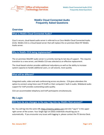
PS EngineeringPMA4000 Series Audio Selector Panel and Intercom SystemInstallation ManualFigure 1-1 PMA40001.4APPROVAL BASIS – FAA- TSO C50cThe PMA4000 p/n 11942, Audio Selector Panels are FAA authorized under FAA-TSO C50c (Audio Amplifiers).All systems comply with relevant portions of EUROCAE ED-14C/DO-160D (Environmental Conditions and Test Procedures for Airborne Equipment), ED12B/DO-178B (Software Considerations forAirborne Equipment) and ED- 18/DO-214 (Audio Systems Characteristics and Minimum OperationalPerformance Standards for Aircraft Audio Systems).Operation is subject to the following conditions:1. This device may not cause harmful interference.2. This device must accept any interference received, including interference that may cause undesiredoperation.1.5SPECIFICATIONSENVIRONMENTAL Qualifications:Temperature Range:Operating:StorageAltitude:FAA AUTHORIZATION, Audio Selector/Intercom:APPLICABLE DOCUMENTS:DIMENSIONS:WEIGHT (With Connectors):Voltage:Maximum Current:Typical operating current:Speaker off:Speaker on, 28V, full radio volumeAudio Selector SpecificationsAudio selector panel input impedance:Input Isolation:Speaker Muting:Speaker Output (into 4 ) with no clipping14 VDC:28 VDC:Receiver Inputs:Unswitched Inputs:Transmitter Selections:Speaker Impedance:Headphone 20ºC to 55ºC-40ºC to 85ºCUp to 25,000 feet in an unpressurized area of the cockpit.C50c, Class ARTCA/DO-214, RTCA/DO-160DHeight: 1.35 in. (3.4 cm) Width: 2.40 in. (6.1 cm)Depth: 6.50 in. (16.5 cm) behind panel12.4 oz. (0.35 kg)11 to 33 VDC (28 Volt w/dropping resistor)0.25 Amp (Externally protected by a 3 Amp circuit breaker.)100 mA250 mA510 -60 dB (min.)-60 dB (min.)2 Watts (min.)8 Watts (min.)4 (Com 1, Com 2, Nav 1, Nav 2)4 (examples: ADF, DME. GPS WPT, Marker, AutopilotDisconnect, Altimeter DH)2 (Com 1, Com 2)4 150 – 1000 Page 1-2Rev. 7, March 2020
PS EngineeringPMA4000 Series Audio Selector Panel and Intercom SystemInstallation ManualHeadphone Output:Microphone Impedance:Intercom SpecificationsIntercom Positions:Music Input:Music Muting:Distortion:Mic Freq. Response, 3 dB:Music Freq. Response, 3 dB:30 mW each headset, with 10% THD into 150 150 - 600 4 places (with individual IntelliVox circuits)1 (Monaural) -30 dB "Soft Mute" 1% THD @ 30 mW into 150 300 Hz - 6000 Hz100 Hz - 18kHz1.6EQUIPMENT SUPPLIEDA.1 ea. of the following units:UnitPart Number11942PMA4000 TSO200-041-0002Page 1-3Rev. 7, March 2020
PS EngineeringPMA4000 Series Audio Selector Panel and Intercom SystemInstallation ManualB.PMA4000 Installation Kit: 250-0041-0001Part Faceplate (Square)Mounting Screws6-32X3/8”Phil-Pan BlackKnob, outerKnob, innerKnob insert pointerConnector Shell MaleConnector Shell FemaleCrimp Pin, maleCrimp Socket, femaleDropping Resistor, 15 , 15 Watt, (required in 28VDC installation)Connector ThumbscrewsConnector HoodMounting Shim– 0.028 inMounting Shim –0.050 in.Operator's and Installation ManualQuan12111112525142111Optional 2 ¼”mounting plate kit (250-004-0005)This kit contains:1 ea. 2 ¼” Mounting plate for instrument hole mounting, P/N 575-004-00011 ea. Mounting Shim, 430-400-00901.8EQUIPMENT REQUIRED BUT NOT SUPPLIEDA.B.C.D.E.F.G.H.1.9Speaker, 4 Headphones, 150 mono, up to 4 as requiredMicrophones, up to 4 as requiredInterconnect WiringContact Crimping Tool, AMP 601966-1 (or MS22520 equiv.), with Positioning Tool601966-5Headphone Jacks (As Required)Microphone Jacks (As Required)Circuit Breaker: 1 ea. 3 amp.LICENSE REQUIREMENTSNone200-041-0002Page 1-4Rev. 7, March 2020
PS EngineeringPMA4000 Series Audio Selector Panel and Intercom SystemInstallation ManualSection II -Installation2.1GENERAL INFORMATION2.1.1 SCOPEThis section provides detailed installation and interconnect instructions for the PS Engineering PMA4000-TSO Series Audio Selector Panel/Intercom System, and PMA4000w/IRS.Please read this manual carefully before beginning any installation to prevent damage andpost installation problems. Installation of this equipment requires special tools andknowledge. The equipment must be installed by an appropriately rated Certified AircraftRepair Station, in accordance with applicable regulations.2.2Unpacking and Preliminary InspectionUse care when unpacking the equipment. Inspect the units and parts supplied for visiblesigns of shipping damage. Examine the unit for loose or broken buttons, bent knobs, etc.Verify the correct quantity of components supplied with the list in Section 1.6 (B). If anyclaim is to be made, save the shipping material and contact the freight carrier. Do NOTreturn units damaged in shipping to PS Engineering. If the unit or accessories shows anysign of external shipping damage, contact PS Engineering to arrange for a replacement.Under no circumstances attempt to install a damaged unit in an aircraft. Equipment returned to PS Engineering for any other reason should be shipped in the original PS Engineering packaging, or other UPS approved packaging.2.3Equipment Installation Procedures2.3.1 Cooling RequirementsForced-air cooling of the PMA4000 is not required. However, the unit should be keptaway from heat producing sources (i.e. defrost or heater ducts, dropping resistors, heatproducing avionics) without adequate cooling air provided.2.3.2 Mounting RequirementsThe PMA4000 must be rigidly mounted to the instrument panel of the aircraft structureand within view and reach of the pilot position(s). Installation must comply with FAAAdvisory Circular AC 43.13-2A. The unit may be mounted in any area where adequateclearance for the unit and associated wiring bundle exist.2.3.3 Mounting Hole configurationFor instrument panel mounting, make openings in the panel according to the templatesand drawing supplied. Depending on the instrument panel thickness, you may elect to usethe shim supplied for the best button depth and mechanical contact. See Appendix B formounting hole layout.200-041-0002Page 2-1Rev. 7, March 2020
PS EngineeringPMA4000 Series Audio Selector Panel and Intercom SystemInstallation Manual2.3.4 Connector AssemblyThe unit connectors are DB25 type. The unit has a male (bottom) a female (top), to prevent incorrect connections. The top connector is generally the output, and the bottomconnector is generally the input connections.These are crimp-type connectors. The AMP Contact Crimping Tool, AMP 601966-1 (orMS22520 equiv.), with Positioning Tool 601966-5 must be used to ensure good qualityharness.2.4Cable Harness WiringReferring to Appendix C, assemble a wiring harness as required for the installation. Allwires must be MIL-SPEC in accordance with current regulations. Two- and threeconductor with shield wire must be used where indicated, and be MIL-C-27500 or equivalent specification. Proper stripping, shielding and soldering technique must be used at alltimes. It is imperative that the correct wire and techniques be used for proper operation.The shield must not be used as ground return. Terminate the shields with a short jumperto the appropriate pin as shown in Appendix C, as close to the unit connector as practical.Refer to FAA Advisory Circular 43.13-2A for more information. Failure to use correcttechniques may result in improper operation, electrical noise or unit failure. Damagecaused by improper installation will void the PS Engineering warranty.2.4.1 NoiseDue to the variety and the high power of radio equipment often found in today's generalaviation aircraft, there is a potential for both radiated and conducted noise interference.The PMA4000 power supply is specifically designed to reduce conducted electrical noiseon the aircraft power bus by at least 50dB. Although this is a large amount of attenuation,it may not eliminate all noise, particularly if the amplitude of noise is very high. Theremust be at least 13 VDC present at the bottom connector, pin 13, of the PMA4000 for thepower supply to work in its designed regulation. Otherwise, it cannot adequately attenuate power line noise. Shielding can reduce or prevent radiated noise (i.e., beacon, electricgyros, switching power supplies, etc.) However, installation combinations can occurwhere interference is possible. The PMA4000s were designed in a RFI hardened chassisand have internal Electromagnetic Interference (EMI) filters on all inputs and outputs.Ground loop noise occurs when there are two or more ground paths for the same signal(i.e., airframe and ground return wire). Large cyclic loads such as strobes, inverters, etc.,can inject noise signals onto the airframe that are detected by the audio system. Followthe wiring diagram very carefully to help ensure a minimum of ground loop potential.Use only Mil Spec shielded wires (MIL-C-27500, or better).Radiated signals can be a factor when low-level microphone signals are "bundled" withcurrent carrying power wires. Keep these cables physically separated. It is very importantthat you use insulated washers to isolate the ground return path from the airframe to allheadphone and microphone jacks.200-041-0002Page 2-2Rev. 7, March 2020
PS EngineeringPMA4000 Series Audio Selector Panel and Intercom SystemInstallation Manual2.4.2Entertainment InputA single entertainment device (MP3 player, iPod, etc.) can be connected to the unit. Install a 1/8-inch stereo jack in a convenient location so that the pilot can plug in the entertainment device into the system.For a stereo input, we recommend tying the left and right channels (tip and ring) together,so both stereo channels are provided to the monaural audio panel, and the audio amplitude available to the audio panel is increased. Audio signal at the entertainment inputmust be a minimum of 1V P-P for optimum music performance. We have found thatsome cigarette-lighter adapters introduce noise into the system due to the voltage switching power supply.2.4.2.1Soft MuteThe PMA4000-system incorporates a "Soft Mute" system. This will mute the entertainment devices during ICS or radio traffic. The entertainment input (P2, pin 25 and 13) isheard by everyone (except by the pilot in ISO mode).NOTE: The Soft Mut e Enable switch i s connected between P2, Pin5 and ground. When thi s pin is ground ed, the soft mute i s inactive,and the PMA4000 is in “Karaoke” Mode.Local oscillators and internal signals from some entertainment equipment can cause undesired interference with other aircraft systems. Before takeoff, operate the entertainmentdevices to determine if there is any adverse effect within the aircraft systems. If any unusual operation is noted in flight, immediately switch off the entertainment devices.NOTE: Use the low-level output of any entertainment device toconnect to the audio panel. Maximum signal level is 3 VAC p-p.DO NOT use a speaker -level output; thi s will cause internal damagein the audio panel.2.4.3 Radio Push-to-TalkAn important part of the installation is the PTT (Push-To-Talk) switches that allow theuse of your aircraft communications radio for transmissions. There are three typical configurations that can be used. Select the case that best fits the installation. Only the personwho presses their PTT switch will be heard over the radio. If the pilot and copilot bothuse the PTT, the copilot position has access to the radio. The pilot position will have PTTcontrol regardless of the copilot when the PMA4000 is in the FAIL-SAFE mode.CASE I: PTT is built into both pilot and copilot yokes.CASE II: PTT is in pilot yoke only. This configuration requires a modified external PTTswitch plugged into the copilot's microphone jack. (See Appendix A). When the copilot'sPTT is pressed, the intercom switches the mic audio from pilot to copilot mic.CASE III: No built in PTT. This requires two built in PTTs to be installed, or modifiedexternal PTT switches to be used. Modify external PTT as required (See Appendix A).200-041-0002Page 2-3Rev. 7, March 2020
PS EngineeringPMA4000 Series Audio Selector Panel and Intercom SystemInstallation Manual2.4.4 Power and 28 VDC Dropping ResistorThe PMA4000 is compatible with both 13.8 and 28 Volt DC systems. A three (3) Ampcircuit breaker is required. Power and ground wires should be at least #20AWG twistedpair.If installed in a 28V aircraft, a 15 , 15 watt dropping resistor must be installed in thepower input.2.4.5 BacklightingThe PMA4000 has automatic lamp dimming of the buttons controlled by a photo-resistor.The photocell located at the center of the unit face will automatically adjust the intensityof the push-button lamps.2.4.6 IntercomAll mic and headphone jacks must have insulating washers, the cable must be Tefloncoated, twisted-shielded wire, and the shield must only be connected to the ground returnwire only at the intercom connector.2.4.6.1Push-to-talk intercomPMA4000 units include a push-to-talk intercom capability. In some extremely high noiseenvironments, it may be desirable to have a push to talk (PTT) intercom, instead of relying on voice-activation (IntelliVox ).To operate the PTT, simply ground P2, Pin 16 (PTT Enable) through a switch. Then,grounding the appropriate pin on the P2 connector through a momentary switch (Pin 4 forthe pilot, Pin 17 for copilot) will open only that intercom channel. The passengers do nothave PTT capability. Their IntelliVox remains active when the ICS PTT enable isgrounded. If PTT is desired for the passenger position, add a momentary, normally open(NO) switch in series with the mic audio input to P2, pin 14 and 15.2.5AdjustmentsThe PMA4000 is factory adjusted to accommodate the typical requirements for mostaircraft configurations. There is an adjustment for the cabin speaker volume, accessed through the left side (viewed from the front) of the unit. To make the necessary adjustments, use a small jeweler's slotted screwdriver. Turning the adjustmentcounterclockwise will increase the volume.2.6Panel Installation1. Insert the PMA4000 from behind the instrument panel.2. Use caution when aligning the holes for the knobs, toggle switches and push buttons.3. If necessary, add the shim spacers between the unit and the backside of the instrumentpanel, so the selector buttons are the correct depth for the shoulder of the switch tomate with the front plate.Note: The total panel thickness should be about 0.100” Add the necessary shims tocome as close to 0.100” as possible. For instance, a .050” instrument panel, add a.050” shim.200-041-0002Page 2-4Rev. 7, March 2020
PS EngineeringPMA4000 Series Audio Selector Panel and Intercom SystemInstallation Manual4. Carefully place the aluminum faceplate over the knob shafts and push buttons, seatingthe push-button shoulders in the panel.5. Secure the unit, using the two # 6-32 round head screws provided.6. Install the knobs over the volume control shaft.2.6.1.1Instrument hole mountingThe PMA4000 can be mounted in a 2 ¼-inch instrument hole, using the adapter plate,part number 575-004-0001 (not supplied).1. Insert a .090” shim (430-400-0090, not supplied) between the PMA4000 and themounting plate. Use caution to align the selector buttons in the openings.2. Secure the mounting plate to the unit and shim assembly with the two # 6-32 roundhead screws provided. Use caution to align the selector buttons in the openings3. Mount the intercom and plate to the instrument panel from behind, using aircraft instrument hardware, not supplied.4. Install the knobs over the volume control shafts.2.7Post Installation CheckoutAfter wiring is complete, verify aircraft power is ONLY on pin 13 of the bottom connector, and airframe ground on bottom connector pin 25. Failure to do so will cause serious internal damage and void PS Engineering's warranty.To avoid stray voltages, the other avionics should be turned off.2.7.1 Operational Checkout1. Apply power to the aircraft and avionics.2. Plug headsets into the pilot, copilot and passenger positions.3. Place the Mic Selector Switch to the Com 1 position.4. Verify that the C1 light comes on. If the push-button is flashing without the PTT activated, stop testing and troubleshoot the microphone PTT installation. A flashing indicator in the COM select button indicates that the key line is grounded.5. Verify proper transmit and receive operation on the pilot and copilot positions, notingthat the PTT switches allows proper transmission on the selected transceiver.6. Verify that the button blinks when the selected transmitter is active.7. Verify that switching to the C2 position causes the button to illuminate and the Com 2receiver to be heard. Verify transmit and receive on Com 2.8. Press the Com 1 push button, and verify that Com 1 and Com 2 receive audio can beheard.9. Verify proper operation of the Nav 1 and Nav 2 receiver sources by selecting themusing the N1 and N2 buttons. Note that the button illuminates to show which source isin use.10. Push in volume control to activate the speaker (SPR) switch. Verify that all selectedaudio is heard in the cockpit speaker. Verify that the audio mutes when the mic iskeyed.11. Verify proper Intercom system operation in the ALL, and ISO modes.200-041-0002Page 2-5Rev. 7, March 2020
PS EngineeringPMA4000 Series Audio Selector Panel and Intercom SystemInstallation Manual12. Verify that the audio selector panel system does not adversely affect any other aircraftsystem by systematically switching the unit on and off, while monitoring the otheravionics and electrical equipment on the aircraft.2.8Final Inspection.Verify that the wiring is bundled away from all controls and no part of the installationinterferes with aircraft control operation. Move all controls through their full range whileexamining the installation to see that no mechanical interference exists. Verify that thecables are secured to the aircraft structure in accordance with good practices, with adequate strain relief. Ensure that there are no kinks or sharp bends in the cables. Verify thatthe cables are not exposed to any sharp edges or rough surfaces, and that all contactpoints are protected from abrasion.Complete logbook entry, FAA Form 337, weight and balance computation and otherdocumentation if required. Return completed warranty registration application to PS Engineering.200-041-0002Page 2-6Rev. 7, March 2020
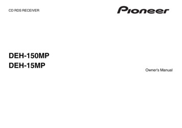
PS EngineeringPMA4000 Series Audio Selector Panel and IntelliVox Intercom SystemInstallation ManualSection III OPERATIONGENERAL INFORMATION3.1SCOPEThis section provides detailed operating instructions for the PS Engineering PMA4000TSO Audio Selector Panel/Intercom Systems. Please read it carefully before using theequipment so that you can take full advantage of its capabilities.This section is divided into three sections covering the basic operating areas of thePMA4000 systems. They are: Audio Selector, Transceiver Selection and Intercom.3.2Audio SelectorFigure 3-1 PMA4000Through the use of momentary, push-button, back-lit switches, it is possible to select anyor all receiver audio.When selected, an internal backlight will illuminate indicating which audio source is selected. The Com toggle switch controls what transceiver is being heard by the pilot andcopilot. "C1" (Com 1) and "C2" (Com 2) pushbuttons select the receiver, and are used tomonitor a com that is not selected for transmit. You will
PS Engineering PMA4000 Series Audio Selector Panel and Intercom System Installation Manual 200-041-0002 Page 1-2 Rev. 7, March 2020 Figure 1-1 PMA4000 1.4 APPROVAL BASIS - FAA - TSO C50c The PMA4000 p/n 11942, Audio Selector Panels are FAA authorized under FAA -TSO C50c (Audio Am-plifiers).