Transcription
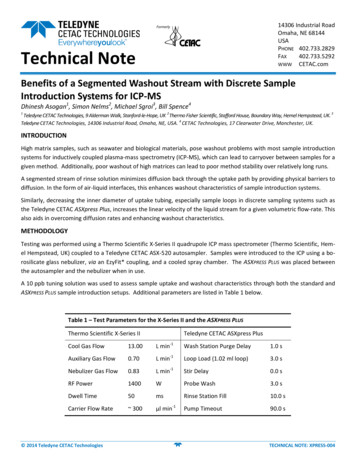
14306 Industrial RoadOmaha, NE 68144USAPHONE 402.733.2829FAX402.733.5292WWW CETAC.comTechnical NoteBenefits of a Segmented Washout Stream with Discrete SampleIntroduction Systems for ICP‐MSDhinesh Asogan1, Simon Nelms2, Michael Sgroi3, Bill Spence41Teledyne CETAC Technologies, 9 Alderman Walk, Stanford‐le‐Hope, UK 2 Thermo Fisher Scientific, Stafford House, Boundary Way, Hemel Hempstead, UK. 3Teledyne CETAC Technologies, 14306 Industrial Road, Omaha, NE, USA. 4 CETAC Technologies, 17 Clearwater Drive, Manchester, UK.INTRODUCTIONHigh matrix samples, such as seawater and biological materials, pose washout problems with most sample introductionsystems for inductively coupled plasma‐mass spectrometry (ICP‐MS), which can lead to carryover between samples for agiven method. Additionally, poor washout of high matrices can lead to poor method stability over relatively long runs.A segmented stream of rinse solution minimizes diffusion back through the uptake path by providing physical barriers todiffusion. In the form of air‐liquid interfaces, this enhances washout characteristics of sample introduction systems.Similarly, decreasing the inner diameter of uptake tubing, especially sample loops in discrete sampling systems such asthe Teledyne CETAC ASXpress Plus, increases the linear velocity of the liquid stream for a given volumetric flow‐rate. Thisalso aids in overcoming diffusion rates and enhancing washout characteristics.METHODOLOGYTesting was performed using a Thermo Scientific X‐Series II quadrupole ICP mass spectrometer (Thermo Scientific, Hem‐el Hempstead, UK) coupled to a Teledyne CETAC ASX‐520 autosampler. Samples were introduced to the ICP using a bo‐rosilicate glass nebulizer, via an EzyFit* coupling, and a cooled spray chamber. The ASXPRESS PLUS was placed betweenthe autosampler and the nebulizer when in use.A 10 ppb tuning solution was used to assess sample uptake and washout characteristics through both the standard andASXPRESS PLUS sample introduction setups. Additional parameters are listed in Table 1 below.Table 1 – Test Parameters for the X‐Series II and the ASXPRESS PLUSThermo Scientific X‐Series IITeledyne CETAC ASXpress PlusCool Gas Flow13.00L min‐1Wash Station Purge Delay1.0 sAuxiliary Gas Flow0.70L min‐1Loop Load (1.02 ml loop)3.0 sNebulizer Gas Flow0.83L min‐1Stir Delay0.0 sRF Power1400WProbe Wash3.0 sDwell Time50msRinse Station Fill10.0 sCarrier Flow Rate 300µl min‐1Pump Timeout90.0 s 2014 Teledyne CETAC TechnologiesTECHNICAL NOTE: XPRESS‐004
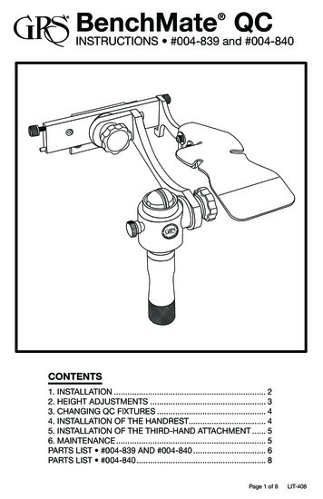
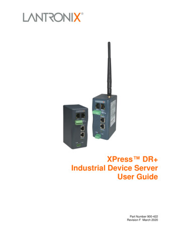
TELEDYNE CETAC TECHNOLOGIESwww.cetac.comSample was introduced into the system and the real‐time display was monitored for changes in signal. Four time pointsof interest were noted:1. Sample Uptake Delay: the time taken for the signal to rise above background to indicate the sample ions hadreached the detector.2. Stabilization Delay: the time taken for the mass flux into the plasma to stabilise and produce a steady signal atthe detector.3. Sampling Time: the time for which a steady signal was being obtained by the ICP‐MS.4. Washout Delay: the time taken for the signal at the detector to fall back to baseline levels from the end of thesampling time.RESULTS AND DISCUSSIONSThe normal uptake profile of the X‐Series II is shown in Figure 1 below. The acquisition delay is approximately 105 s,which comprised 95 s sample uptake delay and 10 s stabilization. The sample probe was moved to rinse after 70 s,resulting in a sampling time of 60 s. Washout of the system also took 105 s, starting from 165 s and reaching baselineat 270 s.Figure 1 – Normal uptake profile of a 10 ppb tuning solution using the standard introduction system using a contigu‐ous carrier stream pumped at 300 µl min‐1The standard introduction system introduces an air‐liquid interface at the front and back end of the sample slug. Thisminimizes diffusion downstream relative to sample flow and results in a sharp rise in signal (after an air‐spike seen atapprox. 95 s). Stabilization is also sharp due to minimal forward diffusion. At the back end of the slug, contact betweenthe sample and the carrier solution is limited to a thin film of sample deposited on the inner surfaces of the sample up‐take path. This is picked up by the contiguous carrier stream and subsequently diffuses back upstream with respect tocarrier flow, resulting in a relatively long washout phase.With the ASXPRESS PLUS system in place, configured with the aqueous sample valve and the aqueous sample loop, thesample uptake delay was reduced to 11 s; however, the design of the ASXPRESS PLUS switching valve means there are noair‐liquid interfaces between the carrier flow and the sample slug. Additionally, the inner diameter of the loop is muchlarger than that of the standard uptake probe ( 2.5 mm and 1.0 mm respectively). Both these factors increase thedegree of diffusion downstream (relative to sample flow) and consequently the stabilization time increased toapproximately 35 s (see Figure 2 below). 2014 Teledyne CETAC Technologies2TECHNICAL NOTE: XPRESS‐004
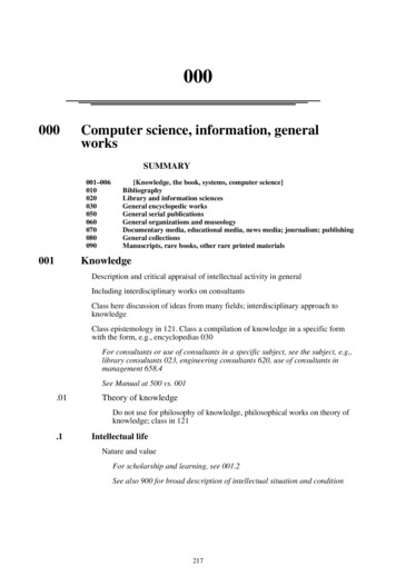
TELEDYNE CETAC TECHNOLOGIESwww.cetac.comFigure 2 – Uptake profile of 10 ppb Tuning Solution using the ASXPRESS PLUS system configured with an aqueousswitching valve and a 1.02 ml aqueous sample loop using a contiguous carrier stream pumped at 300 µl min‐1The sampling time of this system appeared to be 85 s; however, at the chosen flow‐rate and loop volume, this shouldhave been approximately 200 s. Due to the upstream diffusion of the sample, the sample signal started its apparentwashout phase much earlier than anticipated, which means choosing a loop volume using the method sampling timeand the carrier stream flow‐rate would yield poor precision.The washout time of this system was in excess of 180 s, as illustrated in Figure 3 below. This performance is much worsethan the standard sample introduction system, with baseline being achieved around 470 s after the signal is seen to dropoff. Back‐diffusion of the sample upstream in the relatively wide‐bore sample loop lengthens the washout phase con‐siderably.Figure 3 – Washout profile of 10 ppb tuning solution using the ASXPRESS PLUS system configured with an aqueousswitching valve and a 1.02 ml aqueous sample loop using a contiguous carrier stream pumped at 300 µl min‐1 2014 Teledyne CETAC Technologies3TECHNICAL NOTE: XPRESS‐004
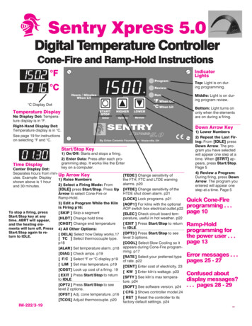
TELEDYNE CETAC TECHNOLOGIESwww.cetac.comMinimizing the inner diameter of the sample loop (using an ‘oils’ sample loop at approx. 1 mm) yielded a similar uptakeprofile. The sample uptake delay was 11 s with a slightly reduced stabilization delay of approximately 30 s and a slightlyincreased sampling time of 95 s. The washout profile, however, was improved significantly with a washout time of 230s, with baseline achieved 360 s after the tuning solution was initially sampled. This time is still greater than the standardsystem’s washout time, however, and the sampling time is still much lower than expected.Figure 4 – Washout profile of 10 ppb tuning solution using the ASXPRESS PLUS system configured with an aqueousswitching valve and a 1.02 ml oils sample loop using a contiguous carrier stream pumped at 300 µl min‐1Numerical simulations of the two sample loops show that, for a given sample type and flow rate, the thinner oils loopwould be washed out more quickly than the aqueous loop due to diffusion processes having a more significant effect inthe larger diameter tubing (see Figure 5 below). The calculated washout profiles from the exit planes of the loops are ingood agreement with the experimental data gathered above, showing a sharper washout phase for the thinner I.D. loopand a return to baseline at an earlier time.1.22,5 mm i.d.1,5 mm i.d.Sample Mass Fraction10.80.60.40.20050100150200250300Time (s)Figure 5 – A graph to show how sample mass fraction varies with time at the exit plane of two 1 ml sample loops ofvarying inner diameter, using ethanol as a sample and water as a contiguous carrier solution pumped at 300 µl min‐1 2014 Teledyne CETAC Technologies4TECHNICAL NOTE: XPRESS‐004
TELEDYNE CETAC TECHNOLOGIESwww.cetac.comUsing a segmented carrier stream introduces a series of air‐liquid barriers in the front and back end of the sample slug inthe uptake path. These barriers minimize diffusion by limiting contact between sample and carrier solution. This resultsin a much sharper uptake profile. Using the aqueous loop on the aqueous valve, the sample uptake delay is increased toapproximately 20 s, but the stabilization delay is now reduced to 7 s (see Figure 6 below).Figure 6 – Uptake profile of 10 ppb tuning solution using the ASXPRESS PLUS system configured with an aqueous switch‐ing valve and a 1.02 ml aqueous sample loop using a segmented carrier stream pumped at 300 µl min‐1The sampling time is now increased to 183 s, which is much closer to the time predicted using the sample loop volumeand the carrier stream flow‐rate. Contact only occurs with a thin film of sample, deposited on the inner surface of thesample uptake tubing, and the carrier solution, which now a small slug. Any diffusion is now limited in space by thephysical size of this slug of carrier solution.Each following slug of carrier solution comes into contact with a lower and lower concentration of sample and the sam‐ple is washed out relatively quickly (see Figure 7). Using the aqueous loop, washout was reduced to 20 s, which is a sig‐nificant improvement on both the standard sample introduction system and the ASXPRESS PLUS system without a seg‐mented carrier stream. Using an oils loop, similar profiles were obtained for the uptake and washout with an uptakedelay of 20 s, a stabilization delay of 5 s, a sampling time of 196 s and a washout time of 16 s.Figure 7 – Washout profile of 10 ppb tuning solution using the ASXPRESS PLUS system configured with an aqueousswitching valve and a 1.02 ml aqueous sample loop using a segmented carrier stream pumped at 300 µl min‐1 2014 Teledyne CETAC Technologies5TECHNICAL NOTE: XPRESS‐004
TELEDYNE CETAC TECHNOLOGIESwww.cetac.comThe segmented washout mechanism is more apparent using an ‘oils’ switching valve (with a 0.030” port diameter, in‐stead of the 0.060” aqueous valve port size) and an aqueous sample loop (see Figure 8 below). There is an obvious‘step’ down in the sample concentration as subsequent carrier solution slugs pass into the ICP. With the OV‐AL combi‐nation, the first bubble is more pronounced but overall washout occurs 10 seconds faster than with the AV‐AL combi‐nation.Figure 8 – Washout profile of 10 ppb tuning solution using the ASXPRESS PLUS system configured with an oilsswitching valve and a 1.02 ml aqueous sample loop using a segmented carrier stream pumped at 300 µl min‐1 2014 Teledyne CETAC Technologies6TECHNICAL NOTE: XPRESS‐004
TELEDYNE CETAC TECHNOLOGIESwww.cetac.comThe timings for the different phases of the transient signal obtained from the tuning solution for all configurations aresummarized in Table 2 below.Table 2 – Method phase timings for sample introduction configurations on a Thermo Scientific X-Series II quadrupole MassSpectrometer.1SampleUptake Delay(s)StabilizationTime(s)Sampling Time(s)Washout Time(s)Total rom the table, it is apparent that the most efficient use of time in the method can be obtained by using a segmentedcarrier stream and a thin sample loop. The optimal combination appears to be using the ‘Oils’ switching valve with the‘Oils’ sample loop and a segmented carrier stream, affording both the longest total sampling time (i.e., minimum diffu‐sion) and the most efficient use of time in the method.However, cavitation of the fluid on sample uptake has to be considered to avoid generating bubbles using high vacuumuptake. Reducing the inner diameter of the sample loop increases the probability of cavitation at a given flow‐rate,since the linear velocity of the sample increases (and hence, the rate of frictional heating increases), converting more ofthe sample into the vapor phase.CONCLUSION AND FURTHER WORKThis note has demonstrated that using a segmented carrier stream, created by introducing bubbles of air, has a benefi‐cial effect on sample washout. Introducing bubbles speeds up washout by physically minimizing the extent of diffusionupstream relative to carrier stream flow.Upstream diffusion is also minimized by reducing the inner diameter of the tubing used for the sample loop, as shownboth experimentally and by numerical simulation. However; if the sample tubing is too small, frictional heating and cavi‐tation processes will dominate, introducing bubbles into the sample stream that would have a detrimental effect onmethod precision.1AV Aqueous Switching Valve (port diameter of 0.060”); OV Oils Switching Valve (port diameter of 0.030”); AL Aqueous Loop(i.d. 2.5 mm); OL Oils Loop (i.d. 1 mm); CCS Contiguous Carrier stream (pumped at 300 µl min‐1); SCS Segmented CarrierStream (pumped at 300 µl min‐1)2The sampling time as a percentage of the total time for all phases3Calculated from 1.02 ml pumped at 300 µl min‐1 for comparison, assuming minimal diffusion* EzyFit is a product of Glass Expansion 2014 Teledyne CETAC Technologies7TECHNICAL NOTE: XPRESS‐004
14306 Industrial Road Omaha, NE 68144 USA PHONE 402.733.2829 FAX 402.733.5292 Technical Note WWW CETAC.com 2014 Teledyne CETAC Technologies TECHNICAL NOTE: XPRESS .