Transcription
SECTION JEngineering GuideDisplacement VentilationPlease refer to the Price Engineer’s HVAC Handbookfor more information on Displacement Ventilation.
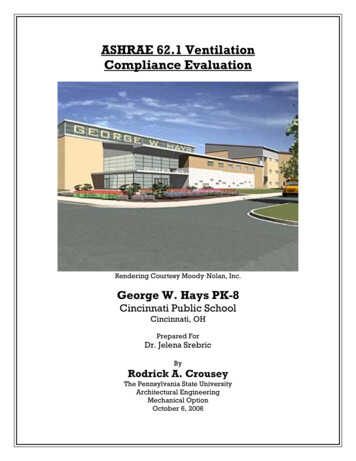
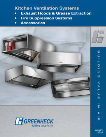
Displacement VentilationEngineering GuideIntroductionDisplacement ventilation is an air distribution technology thatintroduces cool air into a zone at low velocity, usually also at alow level. Buoyancy forces ensure that this supply air pools nearthe floor level, allowing it to be carried up into the thermal plumesthat are formed by heat sources. This type of air distribution iseffective at delivering fresh air to occupants and removing manyof the contaminants associated with heat sources, while creating acomfortable environment.This chapter focuses on the main designcriteria for displacement ventilation systems as well as introducesits common applications. The following pages will go further intodepth on the specific requirements of schools, theaters, health careand industrial spaces.OverviewENGINEERING GUIDE - DISPLACEMENT VENTILATIONAir flow in ventilated spaces generally can be classified by twodifferent types: mixing (or dilution) ventilation and displacementventilation. Mixing ventilation systems (Figure 1) generally supplyair in a manner such that the entire room volume is fully mixed.The cool supply air exits the outlet at a high velocity, inducingroom air to provide mixing and temperature equalization. Since theentire room is fully mixed, temperature variations throughout thespace are small, while the contaminant concentration is uniformthroughout the zone.Figure 1: Mixing (Dilution) VentilationDisplacement ventilation systems (Figure 2) introduce air into thespace at low velocities, which causes minimal induction and mixing.Displacement outlets may be located almost anywhere within theroom, but have been traditionally located at or near floor level.The system utilizes buoyancy forces in a room, generated by heatsources such as people, lighting, computers, electrical equipment,etc., to remove contaminants and heat from the occupied zone. Byso doing, the air quality in the occupied zone is generally superiorto that achieved with mixing ventilation.Induced Air/Thermal PlumeDiffuserBenefitsFlexibility - As load distribution changes within the space, adisplacement system will be able to compensate. For example, ifthe space was designed to have a fairly even load distribution andnow has the loads concentrated to one side, the system is able tocompensate as the buoyant forces drive the supply system andwill draw the supply air towards the loads.IAQ - Because fresh supply air is pooling at the floor level, personalthermal plumes draw fresh air up the body. All of the warm andpolluted air is extracted at the high return. When properly designed,there should always be a greater amount of fresh air in the breathingzone when compared to a conventional dilution system, leading tohigher ventilation efficiency.Green building rating systems, such as the LEED program andGreen Globes have credits that are applicable to displacementventilation systems. See the Green Tips for further information.Energy Savings - Displacement systems present many potentialopportunities for energy savings. The lower pressure dropassociated with displacement ventilation outlets and thecorresponding selection of smaller fan components may allow fora reduction in fan energy. The supply air temperature is typicallyhigher for displacement systems than for overhead mixing systems,and can lead to free cooling from increased economizer hours.Combined with a higher return temperature than overhead systems,the warmer supply temperature of DV systems can cause anincrease in chiller efficiency. Due to a high ventilation effectiveness,the amount of outdoor air that must be conditioned can also bedecreased when compared with a mixing system. This is especiallysignificant in humid climates, where dehumidification of outdoorair is a significant cost.J-2Figure 2: Displacement ventilationLimitationsThe size of displacement outlets can make selecting and locatingdiffusers difficult in areas where there is limited wall area. Ceilingand floor mounted diffusers may help alleviate this issue, whereappropriate.DV systems are limited in their maximum cooling capacity, primarilydue to stratification limits set by ASHRAE (2004a) and ISO (2005).The Price Engineer’s Handbook contains more information on howstratification affects the maximum cooling capacity of DV systems.Chen, Glicksman, Yuan, Hu, & Yang (1999) indicate a maximumcooling capacity of 38 Btu/hft2 [119 W/m2] while ensuring thermalcomfort.Typical ApplicationsDisplacement ventilation is an effective method of obtaining goodair quality and thermal comfort in the occupied space. Spaces wheredisplacement ventilation has been successfully applied include thefollowing. SchoolsTheatersHospitalsCasinos RestaurantsIndustrial SpacesSupermarketsOpen OfficesFor more information on additional imperial and metric sizes please visitpriceindustries.com or contact your local Price representative. Copyright Price Industries Limited 2016.
Displacement VentilationEngineering GuideConcepts and BenefitsDisplacement ventilation is usually agood choice if: The contaminants are warmer and/orlighter than the room air Supply air is cooler than the room air The room height is 9 ft [2.75 m] or more Low noise levels are desiredOverhead air distribution may be abetter choice if:Typical Design ParametersIPSISupply Temperature63-68 F17-20 CReturn Temperature78-85 F26-29 CSupply Face Velocity – Mainly Sedentary Occupancy40 fpm0.2 m/s1.21.2Ventilation Effectiveness (ASHRAE, 2004b)Table 1: Typical DV parameters Ceiling heights are below 8 ft [2.4 m] Disturbances to room air flow are strong Contaminants are colder and/or denserthan the ambient air Cooling loads are high and radiantcooling is not an optionThe thermal plume generated from a pointsource acts differently than a thermal plumegenerated from large objects in the space.For example, a heated cylinder produces aboundary layer and the convective thermalplume takes a different shape than a pointheat source. A point source type expansionof the thermal plume is still present, but at analtered height and with the thermal plumeboundary layer included, shown in Figure 4.The cylinder is a better approximation of anoccupant in the space than a point source.Room Air Flow PatternAir flow patterns in a displacementventilation system are quite different thanin a mixing system. Because of the lowdischarge velocity of displacement outlets,the room air motion is largely driven by theconvection flows created by heat sourcessuch as people, equipment, and warmwindows; or by heat sinks such as cold wallsor windows.The convection flows within theroom cause the formation of horizontal airlayers. The warmest air layers are near theceiling and the coolest air layers are nearthe floor. Copyright Price Industries Limited 2016.Figure 3 & 4: Thermal plume from a point heat source and of a heated cylinder302520Draft Temperature ( F)A thermal plume is a convection currentcaused by buoyancy forces that causes localair to warm and rise above the heat source,entraining surrounding air and increasing insize and volume as it loses momentum, asdepicted in Figure 3. The maximum heightto which a plume will rise is dependent onthe strength of the heat source, as the initialmomentum of the plume will increase. Also,a room with more stratification will reducethe relative density of the plume and, as aresult, limit the height to which the plumewill rise.151050Figure 5: Air layersRoom air moves horizontally across thefloor due to momentum from the supplyoutlet and suction from thermal plumes. Itthen passes vertically through the thermalplumes to a high level in the room where itis returned or exhausted.Vertical air movement (see Figure 5, nextpage) between layers is caused by strongerconvection forces associated with heatsources or cold sinks. Heat sources suchas people, computers, lights, etc. create arising convection flow known as a thermalplume. The strength of the thermal plumeis dependent on the power and geometryof the heat source. The strength of thethermal plume will determine how highthe convection flows can rise before themomental is fully dissipated. Cold sinkssuch as exterior walls or windows cangenerate convection flows down the walland across the floor.For more information on additional imperial and metric sizes please visitpriceindustries.com or contact your local Price representative.J-3ENGINEERING GUIDE - DISPLACEMENT VENTILATIONThermal Plume
Displacement VentilationEngineering GuideDisplacement Ventilation CharacteristicsAir Flow PenetrationA displacement system supplying cool airthrough a diffuser will deliver air along thefloor in a thin layer typically less than 8 in.[0.20 m] in height. The supply air spreadsacross the floor in a similar manner to waterflowing out of a tap, filling the entire space.If obstructions such as furniture or partitionsare encountered, the air will flow aroundand beyond the obstruction, as illustratedin Figure 6. Even rooms with irregulargeometries, as illustrated in Figure 7 canbe uniformly supplied with air.ENGINEERING GUIDE - DISPLACEMENT VENTILATIONWhen the cool air meets a heat sourcesuch as a person or piece of equipment, aportion of the conditioned air is capturedby the thermal plume of the heat source,while the remainder of air continues furtherinto the room.CouchSupply AirDiffuserPartitionFigure 6: ObstructionWhen designing the system to deal withthe cooling demand of the space, thepenetration depth of a displacement diffusercan be 26-30 ft [8-9 m] or more from the faceof the diffuser. For rooms exceeding 30 ft [9m] in length or width, diffusers on severalwalls are suggested to promote even airdistribution.Diffuser Air Flow PatternIn order to avoid draft and minimizeinduction of room air, it is essential for thedisplacement diffuser to uniformly deliverthe supply air across the entire diffuser faceat low velocity. This requires an internalequalization baffle in combination with alow free area face.Yuan, Chen & Glicksman,(1999) recommended 40 fpm [0.2 m/s] inorder to maintain acceptable comfort.Supply AirDiffuserFigure 7: Irregular room geometryA displacement diffuser supplying cool airwill result in an air pattern (typically 5 - 10 F [2 - 5 C] cooler than the room set-point),resembling Figure 8. Due to the densityof the cool supply air, it falls towards thefloor a short distance from the diffuser faceand continues along the floor at a depth ofapproximately 4-8 in. [0.1-0.2 m].When supply air is isothermal (supply air isthe same or less than 5 F [2.5 C] warmerthan the room set-point), the flow will bedistributed horizontally into the space, asshown in Figure 9.Figure 8: Cooling air flow patternJ-4For more information on additional imperial and metric sizes please visitpriceindustries.com or contact your local Price representative. Copyright Price Industries Limited 2016.
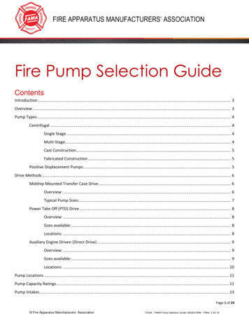
Displacement VentilationEngineering GuideDisplacement Ventilation CharacteristicsContaminant DistributionContaminant distribution is influenced byseveral factors such as supply air method,contaminant source type, location withinthe space, heat sources, and space height.Displacement ventilation improvesoccupant air quality by reducing thecontaminants in the lower portion of theroom. The general upward motion of aircauses contaminants to concentrate withinthe upper zone (Figure 10).Figure 9: Isothermal air flow patternWith displacement ventilation, becausethe upward convection around a personbrings clean air from lower level to thebreathing zone, the air in the breathing zoneis cleaner than the room air at the sameheight. Contaminants that are heavier thanair need to be extracted at a lower levelthrough a second return if they present asafety concern.Temperature DistributionControlling stratification in the occupiedzone is critical to maintaining occupantcomfort. ASHRAE Standard 55 requiresthat the temperature difference betweenthe head and foot level not to exceed 5.4 F [3 C] for a standing person and 3.6 F [2 C] for a seated person.ASHRAE (Chen et al., 1999) has determineda method for calculating the head-to-foottemperature stratification of a displacementsystem based on supply air volume andload distribution. This relationship wasused to develop a design procedure fordisplacement ventilation systems. Usingthis design procedure, an acceptable roomtemperature stratification level can beachieved.For commercial displacement ventilationsystems, supply air temperatures rangingfrom 63 - 68 F [17 - 20 C] can be expected.As well, the temperature difference betweenreturn and supply in a stratified system willgenerally be between 13 - 20 F [7 - 10 C].CONTROL TIPTemperature stratification above theoccupied zone is not a concern as longas the ceiling is over 8 ft [2.4 m]. Toensure stratification control, returnsmust extract from within 1ft [0.33 m]of the maximum ceiling height. Copyright Price Industries Limited 2016.OccupiedZoneMixing VentiVentilationtiilationDisplacement VentilationFigure 10: Contaminant distributionLocation of ReturnsReturns should be located as high aspossible in the space to remove as muchof the stratified zone as possible, ideally atceiling height. If the return is located belowthe ceiling, the air above the return may notbe exhausted properly from the space. Ifthe exhaust is located lower than 7 ft [2 m],some polluted/hot air may remain within theoccupied zone. For lower ceilings it is best toplace the return above the heat source in thespace. In all cases, distributing the returnsevenly thoughout the zone will promoteeven air movement in the room.For more information on additional imperial and metric sizes please visitpriceindustries.com or contact your local Price representative.J-5ENGINEERING GUIDE - DISPLACEMENT VENTILATIONWith mixing ventilation, contaminants arediluted with supply air and are distributedevenly throughout the space. The figurerepresents contamination distributionin a room supplied with mixing anddisplacement ventilation for a typical casewhere the contaminant source is warm (aperson, for example).
Displacement VentilationEngineering GuideHeating with Displacement DiffusersAs previously discussed, displacementventilation relies on buoyancy, or morespecifically, the thermal plumes that surroundheat sources, to drive the air movementthrough the space. These plumes pull thesupply air toward occupants, equipmentand the façade, as well as any other heatsource that requires conditioning. This isall made possible by the pooling of freshcool supply air at the floor level, which canbe used to supply the plumes with cool,fresh air.ENGINEERING GUIDE - DISPLACEMENT VENTILATIONWhen heating is required, the warmer(and relatively buoyant) supply air may nothave enough forward momentum from thediffuser to overcome the effects of buoyancy.This may result in the warm supply airrising to the ceiling and being exhaustedor returned, potentially bypassing theoccupied zone. The warmer the supplyair, the higher the risk of ‘short circuiting,’which can result in poor thermal comfortand ventilation effectiveness, as shown inFigures 11 and Figure 12.Figure 11: Heating air supplyIn practice, for climates with significantheating loads, diffusers with heat-coolchangeover or integrated heat should beused. Alternatively, an auxiliary heatingsystem such a radiant panels could beused. For milder climates, it may bepossible to use the DV system at slightlyelevated temperatures. Experience hasdemonstrated that reasonable performancemay be achieved using up to 5 F [3 C]heating air.Diffusers with Integrated HeatDisplacement diffusers with integratedheat feature a cooling section as wellas a heater. In the case of the perimeterdiffuser, the bottom section is a low velocitydisplacement outlet, used to manage thecooling load and provide ventilation airduring heating periods. The upper sectionincludes a heater in the enclosure that is tobe cycled or modulated as required. Thediffuser, shown in Figure 13, is designed tolook and function like the perimeter radiationsystems common to many commercialbuildings. The fintube or electric coil in theheating section manages the skin load inthe same manner as a typical baseboardheater. The cooling section below continuesto supply ventilation air to the buildingoccupants, typically at isothermal or slightlycooling temperatures. This type of outlet isshown in Figures 14.Figure 12: Isothermal air supplyFigure 13: Perimeter diffuser withintegrated heaterFigure 14: DV diffuser with integratedheat installed along the perimeterIn this configuration, the convective forcesfrom the heating element are not substantialenough to draw the supply air into the frontintake opening for the heater, so potentialshort circuiting of the conditioned supply airis minimized. These diffusers are ideal foruse in perimeter offices, classrooms, andcommercial spaces with large windows.J-6For more information on additional imperial and metric sizes please visitpriceindustries.com or contact your local Price representative. Copyright Price Industries Limited 2016.
Displacement VentilationEngineering GuideHeating with Displacement DiffusersOther types of outlets with heatingfunctions include those that can changetheir discharge pattern to optimize theroom air flow depending on the supplyair temperature. These diffusers providea typical displacement pattern in coolingmode, but can also switch over to a mixingpattern in heating mode. These diffusersincorporate a slot diffuser or a linear bar grillesection in order to increase the dischargevelocity of the air when mixing is required,as shown in Figure 17 and Figure 18.The changeover is actuated automaticallythrough a signal from either the buildingcontrol system or a duct temperaturesensor. When the supply air is warm, it isdiverted into the secondary plenum andthrough the heating diffuser. This allows asingle duct and a single diffuser to provideboth heating and cooling with no manualchangeover or secondary heating systems.Figure 15: Ceiling mounted DV diffuser withheat-cool changeoverFigure 16: DF1W-HC, displacementdiffusers with heat-cool changeoverHot AirCool AirOther Heating OptionsENGINEERING GUIDE - DISPLACEMENT VENTILATIONWindowWindowThere are cases where it is preferred toseparate the heating and cooling functions,particularly in cold climates where the skinload can be significant. Examples of thistype of system include the following:Fan CoilsFan coils may be incorporated into adisplacement system as an alternativeheating source, as long as the fan coil islocated outside the occupied zone and isused to treat perimeter walls and glasswithout mixing the occupied zone. Formore information on fan coils please referto Chapter 13—Introduction to Fan Coilsand Blower Coils of the Price Engineer’sHandbook.Figure 17: Air divertedthrough the heating plenumFigure 18: Air divertedthrough the cooling plenumHydronic SystemsUtilizing a hydronic system in conjunctionwith a displacement system has numerousbenefits. In addition to supplying heat tothe zone, hydronic systems can be used tocompensate for the sensible cooling demandand provide excellent comfort conditionsto a space. There are several methodsfor supplying hydronic heat: perimeterradiation, radiant flooring, radiant panels(Figure 19), and chilled sails (Figure 20).More information on this option can befound in the following section, as well asin Chapter 18—Introduction to RadiantHeating and Cooling of the Price Engineer’sHandbook. Copyright Price Industries Limited 2016.Figure 19: Radiant panelFigure 20: Chilled sailFor more information on additional imperial and metric sizes please visitpriceindustries.com or contact your local Price representative.J-7
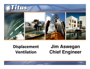
Displacement VentilationEngineering GuideDiffuser TypesDiffuser TypesA wide variety of displacement air diffuser types are available to suit the location restrictions and décor of a particular room or space.In some cases the diffusers are custom fabricated to meet an area’s unique architectural design.There are several categories of displacement diffusers: Free standing diffusers that mount on the floor, in most cases against a wallWall diffusers that integrate into the wall or millworkFloor diffusers that install into the floorCeiling diffusers that install in a ceilingIndustrial diffusers which are designed to withstand harsher environments.Free Standing DiffusersRectangular units are typically placed against a wall or partition or in a corner, but may also be located against pillars or, in some instances,stand in the middle of the room. They are available with rectangular or round faces in order to provide an aesthetic to compliment theroom design. Depending on the design, these diffusers provide a 1 way, 3 way, or radial pattern, as shown in Figures 21 to Figure 24 forrectangular and round faced diffusers and various configurations.The configuration of displacement diffusers are typically driven as much by architectural considerations as by performance characteristics.It is for this reason that there is such a large variety of displacement ventilation products in various shapes and sizes.ENGINEERING GUIDE - DISPLACEMENT VENTILATIONOne common type of these diffusers are the corner outlets. These are specifically designed to fit into a 90 corner in a room and areavailable in flat or rounded faces, depending on the desired look. These diffusers are ideal for applications where wall space may belimited and corners are available for use.Rectangle diffuser1 way air pattern3 way air patternDiffuserPlan ViewPlan ViewFigure 21: Rectangle diffusersCircular diffuserFigure 23: Circular diffusersJ-8Figure 22: DF1L installed against wallCircular air patternCorner air patternPlan ViewPlan ViewFigure 24: DR180 installed in free spaceFor more information on additional imperial and metric sizes please visitpriceindustries.com or contact your local Price representative. Copyright Price Industries Limited 2016.
Displacement VentilationEngineering GuideDiffuser TypesWall Mounted DiffusersWall mounted displacement diffusers are designed to be integrated into the wall (Figure 25). The most common wall integrated diffuserfeatures a narrow plenum and rectangular inlet to accommodate duct connection in a standard 4 in. [100 mm] studded wall. A recesseddiffuser is another example of a wall mounted diffuser (Figure 27). It has no plenum or inlet, and is designed for plenum fed applications,as might be found when mounted in a stair riser, wall or cabinet. Another type of wall mounted diffuser features a linear grille, as shownin Figure 28. These diffusers are typically installed on the perimeter and are available with an integrated heating element.Wall mounteddiffuserWall mountedair patternWall mountedair patternDiffuserPlan ViewFigure 25: Wall mounted diffusersWall mounted recessed diffuserFigure 27: Wall mounted diffusers Copyright Price Industries Limited 2016.ENGINEERING GUIDE - DISPLACEMENT VENTILATIONSection ViewFigure 26: DF1W installed in-wallLinear diffuser enclosurewith integrated heatFigure 28: DLE-H installed against wallFor more information on additional imperial and metric sizes please visitpriceindustries.com or contact your local Price representative.J-9
Displacement VentilationEngineering GuideDiffuser TypesFloor DiffusersDisplacement diffusers are available for integration with a raised floor air distribution system. Figure 29 to Figure 33 are some typesof displacement floor diffusers available. These diffusers produce a low velocity radial pattern across the floor.Displacement floor grilles can also be fan assisted (Figure 31) when additional air volumes are required and a fan terminal is noteconomical.In some instances, such as in a highly aesthetic area or along a perimeter, a continuous grille is preferred. In these situations the linearversion of the displacement floor grille is a good choice (Figure 32).ENGINEERING GUIDE - DISPLACEMENT VENTILATIONRound floor grilleDisplacement floor grilleFigure 29: Floor DiffusersFan powereddisplacement floor grilleFigure 31: Floor DiffusersJ-10Figure 30: RFDD installed in floorLinear floor grilleFigure 32: DFGL installed continusly alonga perimeterFor more information on additional imperial and metric sizes please visitpriceindustries.com or contact your local Price representative. Copyright Price Industries Limited 2016.
Displacement VentilationEngineering GuideDiffuser TypesCeiling DiffusersDisplacement ventilation diffusers may also be located outside of the occupied zone, which is a good location for a diffuser in a spacethat either does not have a lot of wall space or where space is at a premium, such as in a private office. These diffusers can either fit into a T-bar ceiling system or can be mounted directly to ductwork. Some of these products are also available with heat-cool changeoveroptions (Figure 32 and Figure 34)Due to the supply air falling through the warmer air above, there will be some amount of heat gain of the supply air before it reachesthe floor. There is also the potential for some entrainment of pollutants that are collected in the upper zone. While the amount of heatgained and pollutants entrained is small, it is often desired to minimize this as much as possible. It is therefore common to locate thesupply outlets near a wall to take advantage of the Coanda effect, wherein the supply air will travel down the wall to the occupied zone.This reduces the size of the area where the supply air interacts with the stagnant air, and thereby the heating effect.If the face velocity of the ceiling mounted displacement diffuser is within the rage recommended for those located in the occupied zone,the velocity of the air falling past occupants should remain low. To ensure that this does not pose a risk of draft, it is good practice toplace diffusers that cannot be located near a wall above corridors or office pathways (Figure 36 and Figure 37)Ceiling diffuserFigure 33: Ceiling DiffusersFigure 34: DF1W-HC installed in wallIndustrial DiffusersFor the industrial environment, diffusers must be able to withstand impact from moving equipment or be mounted above the workingspace and designed to supply air deep into the space. Flat industrial displacement diffusers are intended to be placed on the industrialfloor space and provide supply air. The robust design allows this diffuser to withstand the impact forces common to the industrial sector.Industrial diffusers are designed to be mounted above the occupied zone, and have integrated heating and cooling supply air modes(Figure 35 and Figure 36).Free standing industrialdiffuser with heat-cool changeoverFigure 35: Industrial Diffusers Copyright Price Industries Limited 2016.Duct mounted industrial diffuserwith heat-cool changeoverFigure 36: DFXi installed in floorFor more information on additional imperial and metric sizes please visitpriceindustries.com or contact your local Price representative.J-11ENGINEERING GUIDE - DISPLACEMENT VENTILATIONCeiling diffuserwith heat-cool changeover
Displacement VentilationEngineering GuideDesign Procedure - Displacement VentilationASHRAEThe following step by step design procedure is offered as a simplified approach to determine the ventilation rate and supply air temperaturefor typical displacement ventilation applications. The procedures presented are based on the findings of ASHRAE Research Project-949(Chen, Glicksman, Yuan, Hu, & Yang, 1999) and the procedure outlined by Chen & Glicksman (2003).The design procedure applies to typical North American office spaces and classrooms. These procedures should be used with carewhen applied to large spaces such as theaters or atria; a computational fluid dynamic analysis (CFD) of large spaces is recommendedto optimize the air supply volume.Only the sensible loads should be used for the preceding calculations.These calculations are only for determining the air flow requirementsto maintain the set-point in the space; the total building load remains the same as with a mixing system.Step 1: Determine the Summer Cooling LoadUse a cooling load program or the ASHRAE manual method to determine the design cooling load of the space in the summer. If possible,assume a 1.1 F/ft [2 C/m] vertical temperature gradient in the space for the computer simulation as the room air temperature is notuniform with displacement ventilation. Itemize the cooling load into the following categories: The occupants, desk lamps and equipment, qoe (Btu/h [W]) The overhead lighting, ql (Btu/h [W]) The heat conduction through the room envelope and transmitted solar radiation, qex (Btu/h [W])Step 2: Determine the Cooling Load Ventilation Flow Rate, QDV:ENGINEERING GUIDE - DISPLACEMENT VENTILATIONThe flow rate required for summer cooling, using standard air, is:IPJ1SIJ1Where:QDV air required to satisfy the sensible cooling load in a DV system, cfm [L/s]ρ air density, lb/ft³ [kg/m3]cp specific heat of the air at constant pressure, Btu/lb F [kJ/kgK]thf temperature difference from head to foot level, F [ C]Step 3: Determine Flow Rate of Fresh Air, Qoz:ASHRAE Standard 62.1-2004 Ventilation Rate Procedure includes default values for ventilation effectiveness. From ASHRAE Standard 62.12004: equation 6-1 is used to determine the breathing zone outdoor air flow Vbz and equation 6-2 is used to determine the zone outdoorair flow Qoz.J2where:Qoz the required volume of outdoor air, as determined from ASHRAE Standard 62.1-2004, based on room application.Note that local codes may not allow the discount for the ventilation effectiveness, or may have stricter requirements.Rp outdoor air flow rate required per person, as determined from Table 6-1 in ASHRAE 62.1-2004, cfm/person [L/s person]RA outdoor air flow rate required per unit area, as determined from Table 6-1 in ASHRAE 62.1, cfm/ft 2 [L/
priceindustries.com or contact your local Price representative. ENGINEERING GUIDE - DISPLACEMENT VENTILATION Displacement ventilation is an air distribution technology that . displacement ventilation for a typical case where the contaminant source is warm (a per