Transcription
Leak MeasurementTechniques13th Annual Implementation WorkshopOctober 23-25, 2005Houston, TexasInterContinental Hotel1
Why Quantify Emission Rates?Justification for repair/control costs. Prioritization and optimization of efforts? Typically 80 to 90% of emissions contributedby the top 10 leakers at each site.Objective performance monitoring. Potential to generate marketable GHGcredits. 2
Performance Requirements: Reasonable cost. Readily available. Sufficient accuracy for economicevaluations (e.g., 25% or better).3
Traditional Approaches: Target Applications:Generally limited to smaller to mediumsized equipment components and leak rates. Basic constraints:Requires easy or supplied access to leaks. Potential Issues:Composition dependencies.Potential safety issues (H2S or relief events).Backpressure limitations.Detection limitations.High temperature surfaces.Surfaces with heavy ice or frost accumulation.4
Traditional Approaches: Methods:Bagging Time consuming and costly to apply.Applicable for small to moderate leak rates.End-of-Pipe Capture and Measurement Techniques Calibrated BagFull-flow flow meters.Hi-Flow Sampler Convenient approach for smaller to medium sized leaks (e.g., 8 to10 scfm or 29,400 to 36,700/y at 7/mscf).Velocity Probes.5
Non-traditional Methods: Target Applications:Vent and flare systems.Area, and volume sources.Inaccessible or unsafe to access sources. Basic Constraints:Generally more costly and complicated to use. Potential Issues:Weather dependent.Susceptible to interferences.Require suitable downwind access (i.e., remotesensing methods).Potentially reduced resolution and accuracy.6
Non-traditional Methods: Methods:Tracer techniques:In–line tracer methods. Transient response (e.g., ASHRAE building methods). Pollutant-to-tracer ratio technique. Remote plume sensing methods.US EPA (2006): ORS Protocol(www.epa.gov/ttn/emc/prelim/otm10.pdf). DIAL (ftp://public:access@ts.clearstone.ca). Back-calculation using atmospheric dispersion modelsand upwind/downwind monitoring data. AIRDAR. 7
Non-traditional Methods: Methods:Source modeling (i.e., estimation from processoperating data and engineering principles):Mass balance and energy balance techniques. Process simulators. 8
Where should measurement effortsbe focused?9
Compressor Seal Vents: Causes of Emissions:Seal wear. Typical Measurement Problems:Potentially multiple leakage points: Centrifugal:Lube oil degassing reservoir.Seal Vent. Reciprocating compressors:Distance piece and packing case vents.Lube oil drain tank vent.Crank case vent.Potentially large flows.Minimal tolerance to any back-pressure.Fouling due to lube oil mist.10
Compressor Seal Vents: Typical Measurement Problems:Oily roof-tops and limited roof-top access.Lack of ports on vent lines.Possibly weather caps on vent outlets. Measurement Approaches.Vane anemometers.Diaphragm meters or calibrated bags wheresome backpressure can be tolerated.Hi-Flow SamplerQuantitative remote sensing methods.Permanent Solutions:Flow switches. Rotameters. 11
Blowdown and Vent/FlareSystems: Causes of Emissions (During PassivePeriods):Purge gas.Leakage past the seats of blowdown/relief valves(5 to 10% leak and 1 to 2% of these contributeover 75% of the emissions).Blowdown or drain valves not fully closed.Compressor seals. Typical Measurement Problems:Potentially large flows.Difficulty accessing end of pipe.Limited or no suitable ports for insertion ofvelocity probes.12
Blowdown and Vent/FlareSystems: Typical Measurement Problems:Low flow velocities.Potentially wet or fouled environment inside pipe.Safety concerns (relief episodes). Measurement Approaches.Micro-tip vane and thermal dispersionanemometers.In-line tracer tests.Ultrasonic sensors (portable & online).Remote sensing methods.Permanent Solutions:Ultrasonic transit-time flow meters. Flow switches. 13
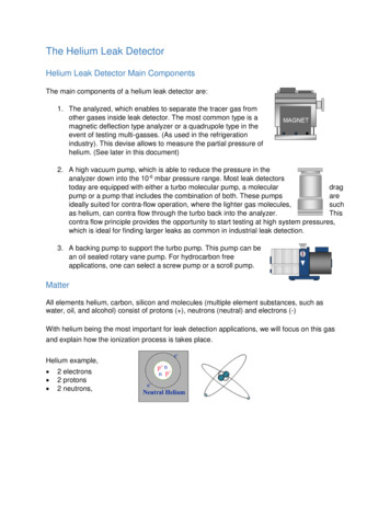
Storage Tanks: Causes of Emissions:Working and breathing losses.Flashing losses.Unaccounted for contributions: Unintentional Gas carry-through.Leaking drain and dump valves.Malfunctioning level controllers.Inefficient upstream gas/liquid separation.Piping changes resulting in storage of unstablized product.Non-routine storage of unstabilized product in atmospherictanks. Malfunctioning vapor recovery systems:Faulty blanket gas regulators or pressure controllers.Fouled vapor collection lines.Leaking roof fittings and seals.14
Storage Tanks: Typical Measurement Problems:Multiple roof openings.Edge-of-roof access only.Dependence on pump in/out activity and meteorological conditions.Fall protection and potentially confined space training required.Interpretation and extrapolation of results. Measurement Approaches:Velocity profiles across openings. Vane anemometers.Tracer techniques.DIAL Engineering CalculationsAPI E & P TANKS Model (Flashing, working and breathing losses).15
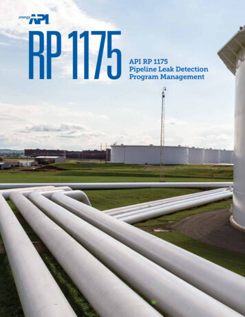
Storage Tanks – RemoteEmissions Measurement16
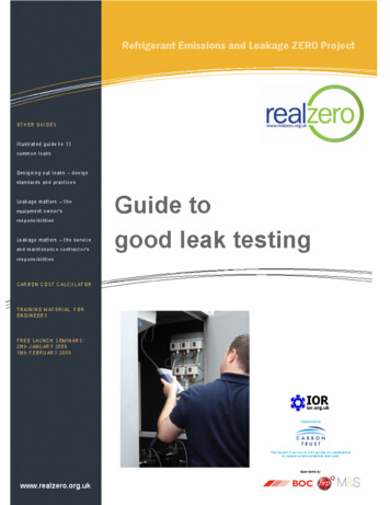
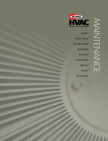
Storage Tanks – UnaccountedLossesFacilityTHC Emissions3MethaneEmissions3[10 m /year][tonnes CO2E/year][ /year]Gas Plant #1NANANANAGas Plant #2NANANANAGas Plant #31 66357Gas Plant #4NANANANAGas Plant #595931 32524 559Gas Plant #6NANANANAGas Plant #7NANANANAGas Plant #84 4692 65137 8011 880 267Gas Plant #9NANANANA6 2272 80139 9392 346 1976923114 438260 689AVERAGE3Value of LostProduct[10 m /year]TOTAL3GHG Emissions813441 371- Value of emissions based on a 6.78/GJ for natural, 8.13/GJ for propane, and 9.63/GJ for butane and condensate.17
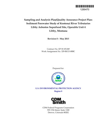
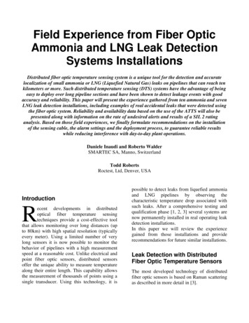
Best options by source:SourceHi-FlowEnd-of-PipeFlow XXXXXBlowdown SystemsCompressor SealsXFlare SystemsTanksNon-point w/LeakSensorsXXXXXXXXXXXX18
Conclusions on Leak Measurement:A selection of measurement techniques isneeded. Instrumented solutions are the best choicefor large potential emitters: Compressor seals.Flare and vent systems.Metering of gas blanketing systems.19
Detection limitations. High temperature surfaces. Surfaces with heavy ice or frost accumulation. 5 . Lube oil drain tank vent. Crank case vent. Potentially large flows. Minimal tolerance to any back-pressure. Fouling due to lube oil mist. 11