Transcription
FINDINGS OF EXPERIMENTS USING WATER MIST FORFIRE SUPPRESSION IN AN ELECTRONIC EQUIPMENT ROOMHalon Options Technical Working Conference, May 7-9, 1996 (NMERI)Jack R. Mawhinnev, P. En&Hughes Associates, Inc.4Ottawa, CanadaABSTRACTThis paper presents highlights from a 3 year study conducted at the National Research CouncilCanada (NRCC), jointly funded by NRCC and National Defense Canada, which investigatedperformance criteria for a combined “intelligent” fire detection and zoned water mist fire suppressionsystem. The NRCC study identified basic design requirements for a multi-zone water mist suppressionsystem to protect a control room underfloor, individual electronic switchgear cabinets, and arrays ofcable trays, using water mist. The experimental program clarified what is feasible for using water mist tosuppress fires in electronic equipment cabinets and rooms. The study also investigated the feasibility ofdesigning a fire detection system capable of pin-pointing the location of a fire in a compartment to withinI m, and activating one or more specific zones o f a water mist system.The experimental work supports two conclusions about the use of water mist in electronicequipment rooms. The first is that water mist does not perform well when applied in a “total flooding”mode in obstructed compartments. Total-flooding application resulted in locally unpredictable variationsin spray velocity and flux density distribution, the results of “random splashing”. Extinguishment wasequally unpredictable. The second conclusion is that the most important factor in determiningsuppression performance was control over the direction of application, or “directionality” ofthe watermist. In other words, the designer should devote more attention to the direction of application of thespray, than to drop-size distribution and mass flow rate. It was noted that very fine sprays ( D v o . 90microns) were not suitable for electronic equipment areas, in that mist drifted throughout the entire room,outside the area of intended application. Coarser sprays, e.g., with 200 Dv0.Y 400 microns, providedbetter control over spread of humidity in the facility, as well as better penetration of grouped cables.The paper describes highlights from the NRCC study into advanced fire detection features of an“intelligent” fire detection system, needed to allow the water mist system to be subdivided into zoneswithin a large volume space.INTRODUCTIONThe telecommunications and utilities industries have avoided the use water as a fire suppressant onelectronic and electrical equipment, because of concerns about “water damage”. For electronicequipment, applying a conductive and possibly corrosive fluid to powered circuit boards may cause shortcircuits (short term loss of function), or long term damage due to pitting or corrosion of chips andconnectors. For more robust electrical equipment, water damage relates to the danger for electrical shortcircuits as well as corrosion at connectors and in windings. For these reasons, so-called “clean agents”,such as Halon 1301, have been the agents of choice for electronidelectrical equipment environments.That is, until recently. Having been identified as a major ozone-depleting substance, Halon 1301 isbeing rapidly phased-out of use. The National Fire Laboratory (NFL) at the National Research Council
Canada, has been studying the feasibility of using environmentally benign fine water sprays (water mist)as an alternative to Halon to protect facilities involving electronic and electrical equipment. The“Combined Intelligent Fire Detection and Water Mist Fire Suppression System Project”, or IntelMistTMProject, has been supported jointly by the Department of National Defence, and National ResearchCouncil Canada. An “intelligent” fire detection system is one that uses techniques of artificialintelligence to process analog information on fire conditions, which can select and initiate an appropriateresponse from a set of possible responses.To date, the NRCC study has identified basic design requirements for a multi-zone water mistsuppression system to protect a control room underfloor, individual electronic switchgear cabinets, andarrays of cable trays [I]. The experimental program clarified what is feasible and what is not feasible forusing water mist to suppress fires in electronic equipment cabinets and rooms. The study alsoinvestigated the feasibility of designing a fire detection system capable of pin-pointing the location o f afire in a compartment to within 1 m, and activating one or more specific zones of a water mist system [2].This paper reports on the project findings in these areas.With respect to the matter of water damage, based on a review ofNational Defence and utilityindustry telecommunications equipment scenarios, it was concluded that damage potential is equipmentspecific. This was supported by a study done for New Zealand Telecom, on the effects of using watersprays on printed circuit boards, which concluded that normal mains water can be used without causingharm in many cases; but demineralized water may be needed in some cases [3]. The appropriateness ofusing water as a fire suppressant must be decided on the basis of specific information about the internaldesign, value, replaceability, and intended function of the equipment. Methods for assessing sensitivityto water damage in specific equipment are needed, so that informed decisions can be made as to thebenefits or otherwise of using water mist as a fire suppressant.A review of fire hazards within control rooms, computer and some switchgear rooms revealed thepresence of Class A fuels, such as waste paper, computer supplies, foam stuffed operator’s chairs, andcoffee room supplies. The work conducted to develop a water mist system for the electronic andelectrical equipment did not address fires in such materials. A complete fire protection strategy for ahigh value facility would have to take such fires into account.This report summarizes findings on the following elements of the IntelMist project:a) water mist characteristics needed to extinguish fires in electronic cabinets;b) water mist characteristics needed for underfloor cable plenums, and overhead cable trays; andc) characteristics of the detection system needed to allow zoning of the water mist system.EXTINGUISHING IN-CABINET FIRESFire ScenarioFire statistics reported by Johnson [4] indicate that, with the low fire-spread rate typical of fires inelectronic equipment, the majority of cabinet fires self-terminate or are suppressed using handextinguishers or hose reels. There are often large masses of communication cables leading into and outof the electronic cabinets, however. If fire spreads into these cable arrays, it may not self-terminate,particularly if older-generation, non-fire retardant wiring is mixed with more fire-resistive wiring [ 5 , 61.16HOTWC.96
In tests conducted at the Swedish National Testing Laboratory (SP) in Sweden [7, 81, two telephonenetwork frames were ignited and allowed to burn. One cabinet self-extinguished in I O minutes. Thesecond cabinet “burned” for 70 minutes at less than I O kW; rose briefly to a peak heat release rate of -38kW, then reduced to about 20 kW. The tests confirmed that fires in switchgear cabinets andTelecommunications (TC) main frames are small, slow-growing fires, which can usually be extinguishedby cutting the electrical power. During the early stages of burning, and even at full-flaming, the potentialfor spread to adjacent equipment is low because of the low energy of the fire. The most serious threat toproperty and function is from the spread of corrosive smoke throughout the facility.The built-in passive features that limit the spread of tire in electronic equipment cabinets bring intoquestion whether an active fire suppression system is needed. After review of several National Defencefacilities, with mission-critical equipment on uninterruptible power supplies, and also the circumstance ofa public power utility operating remote, unmanned switchgear facilities through micro-wavetransmissions, it was concluded that an in-cabinet fire suppression system can be justified under certaincircumstances. This study then concentrated on determining how to extinguish an electronic equipmentcabinet fire using water mist.It was established quickly that it was impossible to extinguish a fire inside an electronic cabinet byapplication of mist to the exterior of the cabinet. The subsequent experimentation was based onapplication of mist to the interior of each cabinet. Two cabinets were used for fire tests. Cabinet A was0.86 by 0.80 by 1.69 m (2.8 x 1.6 x 8.6 ft) high, with two magazines ofvertically mounted printed circuit(“PC”) boards, and bottom-to-top ventilation from an underfloor opening. Cabinet B was 0.98 by 0.78 mwide by 1.70 m (3.12 x 2.6 x 5.6 ft) high, with horizontally-oriented PC boards, and horizontal air flowfrom an internal ventilation plenum and fan. Both cabinets were equipped with hinged doors. When thedoor was closed, ventilation air escaped from the cabinets through grilles i n the cabinet doors and topsurface. Tests were conducted using different rates of ventilation through the cabinets, ranging from 0,0.25 to 1 .O m/s (0, 50 to 200 fpm) entrance velocities. Thermocouples were situated in the cabinet torecord temperatures during fire tests. A gas sampling probe was installed between the two magazines ofPC boards, connected to 3 m (10 ft) long 6 mm (1/J”) diameter heated sampling line, so thatmeasurements of O2and H2O (vapor) could be madeA representative fire was created using two 300 by 100 mm (12 x 4 inches) PC boards mounted withthe component surfaces facing each other, 32 mm ( I .25 inches) apart. An electric stove element wasinserted between the two PC boards. Upon exposure to the red-hot element, the fire-resistive boards firstemitted a strong, acrid odor: and wisps of white smoke appeared after 1 or 2 minutes. By four minutesthick smoke with very strong odor was emitted; at 5 minutes many plastic surface components were“bubbling” and melting. In some cases the faces of the boards would spontaneously break into flamingcombustion. If not, flaming was initiated by piloted ignition at 8 minutes. Due to the dlfficulty ofpurging the laboratory of the irritating, noxious smoke given off by the PC boards, the test fire wassimulated using two pieces of 6 mm (114 inch) thick masonite board instead of PC boards. Heat from thestove element was reflected between the two surfaces, creating the representative “sandwich” tire. Theheat release rate was estimated to be between 3 and 6 kW. To extinguish this fire, it would be necessaryto wet or cool the board surfaces inside the 32 mm (1.25 inch) space between the boards.Range of Sprav CharacteristicsA variety of nozzles were tested in order to identify the characteristics needed to extinguish the testtire. In cabinet A, sprays were applied from below the fire, in the same direction as the ventilation airHOTWC.9617
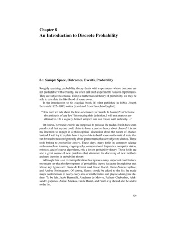
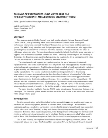
flow; and from above the fire, counter to the ventilation air flow. Four distinct spray qualities wereconsidered:1.Very tine, low momentum mist (DvO.9 75 microns) intended to be drawn through the cabinet bythe internal ventilation air-flows. Low-pressure, air-atomizing nozzles with a flow rate of 1.5L/min per nozzle; spray cone angle 20”, were used.2. A moderate momentum mist with Dv0.9 125 microns. A Semco nozzle was selected, with flowrate 3 L h i n at 80 bar (0.8 gpm at 1,175 psi), and spray cone angle of 90”. One or more nozzlesdischarged into each of the upper and lower compartments (Cabinet A). It was expected that thehigh velocity and small drop size would cause mist to penetrate closely spaced PC boards.3. A high flow rate nozzle was used to generate a coarser spray (Dv0.9 z 300 microns), intending to“drown” the fire in the cabinet. A Spraying Systems Company (SSC) 3/4 7GS nozzle was used,with spray cone angle of 150” and flow rate of 35 L/min at 5 bar pressure (9.2 gpm, 74 psi).4. Mist was generated by release of super-heated water through simple orifices, to create a spray witha high percentage of very tine drops (DvO.9 20 microns) produced by condensation from steam,combined with a relatively coarse spray created by the shattering of water during the flashingprocess [9]. The mist was expected to reduce the oxygen concentration in the cabinet.Summarv of Findings from the Cabinet Fire Supmession TestsOver 90 fire suppression tests were conducted in the cabinets. The experimental work demonstratedthat it is possible to extinguish small fires in closely spaced electronic circuit boards using water mist.The manner in which the mist is injected into the cabinet is critical to performance, however.Inappropriate selection of nozzles and spray characteristics will result in either waste of water, or failureto extinguish tires. Key findings from the tests are stated as follows.I . The geometry of closely-spaced printed circuit boards dominates the distribution of mist withincabinets, hence the ability to extinguish tires. Unless spray is injected in a direction that allowsmist to penetrate the narrow inter-board spaces, fires are not extinguished. This finding isconsistent with the study conducted by Grosshandler, et. al. [lo], which describes the limited depthand width of effective extinguishment zones within parallel circuit boards.2. Control over the direction of the spray was the single most important factor to ensure the ability ofwater mist to extinguish fires in cabinets filled with parallel arrays of circuit boards. Controllingdirection of application had a greater effect on performance than either drop size distribution orflux density.3. Very fine sprays with low momentum and low mass flow rate were ineffective at penetrating arraysof closely spaced circuit boards. Spray penetrated only the few channels that were parallel with theaxis of the spray.4. There was no measurable advantage to the fact that the fine spray could be carried with theventilation air into the board spaces. At typical ventilation velocities, the total mass of watersuspended in drops small enough to be carried with the ventilation air was insufficient to achieveextinguishment.5 . As shown in Figure 1, only the fraction of the spray that had the right “directionality” relative tothe PC boards was effective. Most of the water in wide-angle cones was wasted. Increasing thedrop size distribution and flow rate only meant that more water was ineffective.18HOTwC.96
Mist generated by flashing of super-heated water did not increase the rate of oxygen displacementby water vapor. The temperature of the steam reduced rapidly to 35C, at which temperature thewater vapor concentration was insufficient to affect oxygen concentration. Extinguishmentdepended on the same factors as for conventional sprays. A discussion of these experiments isprovided in reference [ 9 ] .Very tine drop size was not an advantage for electronic cabinets. The drifting of fine mistthroughout the room raised humidity and condensation levels in areas well removed from the fireCoupled with the soluble HCI which can be expected to be present with the burning of plasticwiring, the uncontrolled spread of slightly acidic, ultra-fine mist is undesirable. Coarser sprays(Dv0.9 300 microns) were just as effective, and remained in the vicinity of the point ofapplication.Changing from conical spray cones to linear spray distribution, provided extinguishing capabilityover the full width and height of the circuit boards. Because all of the water was used effectively,the overall water requirement from linear distributors was much less than for wide cone-anglespray nozzles, Water discharge rates of approximately 3.7 Liminim (0.3 gpmift) were successful,(but not optimized).For many types of cabinets, horizontal or vertical tubes can be installed to discharge lines of smalldiameter jets into the magazines of printed circuit boards. Direction can be changed as needed tosuit several local geometries in a single cabinet. Due to wide variability in electronic and telecomcabinet design, the mist system tubing must be custom fit.Conical sprayLinear sprayParallel . -urfEffective Sumression.ZoneFigure 1 , Zones of effective fire suppression in arrays of printed circuit boards, usingconical and linear sprays.
EXTINGUISHING FIRE IN UNDERFLOOR CABLE PLENUMSFire scenarioElectrical power cables and communication wires in switchgear rooms, control rooms and computerrooms are often spread beneath a raised floor, from where they are brought up into the equipmentcabinets on the floor above. Wires and cables may be run neatly in trenches or cable trays, or they maybe run freely in every direction. In some facilities, every square metre of floor area could be coveredwith several layers of plastic-sheathed cables, including some abandoned older vintage wiring that wasdisconnected by not removed. Ignition could occur if insulation was damaged, with the eventualoccurrence of a short circuit and arcing. If the power supply could not be cut (Le., "uninterruptible"(UPS)), sustained arcing could ignite the plastic sheathing and spread.Current North American standards for plastic cable insulation ensure low combustibility, whichmeans that unless there is a sustained high-energy heat source, the insulation will self-extinguish.Nonetheless, most recent telecommunications facility fires have involved cables, rather than cabinets. Aswith the cabinet fire scenarios, whether passive fire safety measures are sufficient reason to omitinstallation of an active suppression system depends on the conditions at specific facilities.The fire suppression tests carried out in these experiments are based on an assumed fire scenario inwhich arcing generates a self-sustaining fire in a bundle of closely spaced communication wiring. Tosimulate such a fire, a cable bundle was prepared using 12 pieces o f 2 5 pair PVC-jacketed fire retardantcommunications cable, 300 mm (12 inches) long. In the midst of the 12 pieces were placed 3 lengths of15 mm ( 5 / 8 inch) diameter sisal rope, which had been soaked in diesel fuel. Once the diesel-soaked sisalrope began to burn, plastic insulation softened and charred, and began to contribute to the burning. Thefire would spread along the bundle, attaining a length of 200 mm (8 inches) within one minute. The heatrelease rate from the test fire was estimated to be between 3 and 6 kW. The bundle was laid on the crosssupports of a cable tray, so that it was approximately 30 mm ( I .2 inches) above a concrete floor, suchthat air was available from all sides.The PlenumFire tests were conducted in a simulated underfloor plenum, 6 m x 9 m x 0.6 m (20 ft x 30 ft x 2 ft)high. The vertical floor supports created distinct channels, 0.4 m wide by 0.6 m high by 9 m (16 in. x 2 ftx 30 ft) long in one direction, and 0.6 m x 0.6 m x 6 m (2 ft x 2 ft x 20 ft) long in the other direction.When viewed at any angle other than orthogonal to the axes of the room, the floor supports obstructedthe lateral distribution of water spray. The appearance was similar to underfloor arrangements viewed, inwhich many cables rose from the underfloor into equipment above the floor. A ventilation system wasprovided, such that air circulated through the underfloor plenum, and rose into the control room throughopenings in the floor covering.Spray Nozzles and Test ArrangementTwo types of sprays were used in the underfloor. The first was a single-point discharge nozzleplaced at mid-height of the plenum on an end wall, which produced a 180" fan of spray of 3 m (10 ft)radius. It was intended to extinguish fires anywhere within the fan area. The mist, produced by flashingof superheated water, was rich in aerosol-sized droplets and water vapor, but also contained a substantial
mass portion with Dv0.9 200 microns. Discharging 50 L h i n (13.2 gpm), the nominal flux densiw was3.5 Liminim’ (0.09 gpm/ft2).The second spray was produced using lines of nozzles oriented so that spray was discharged in adirection parallel with the vertical floor supports. The nozzles were spaced 0.3 m (1 ft) apart,symmetrically within each 0.6 m ( 2 ft) wide channel created by the floor supports. The area of coverageextended 3 m (10 ft) from the middle axis of the test room to the walls, Le. 1.8 m2(20 ft’) per pair ofnozzles. Each swirl type nozzle discharged approximately 5 Limin (1.3 gpm), for a nominal flux densityof 5.6 Llmidm’ (0.14 gpmlft?). This spray had a Dv0.9 300 microns. The cable bundle was placed atvarious locations within the intended area of coverage of each nozzle system.Summarv of Findings from the Underfloor Fire Suppression TestsThe following points summarize the findings of the twenty three suppression tests conducted in theunderfloor.1.Water mist extinguished small incipient fires in electrical cables by direct fuel wetting. Very finemist consisting of suspended droplets was ineffective, even when the fire was completely obscuredby the fine mist. Extinguishment occurred only when enough water penetrated between theindividual cables in the cable bundle. The finest mist fraction could not penetrate between thecables. There was therefore no advantage in using very fine water mists (Dv0.9 I00 microns) forincipient fire suppression in underfloor cable plenums.2. Sprays with drop size distribution in the range 200 Dv0.9 400 microns, are likely to be effectivewith both cable fires and other class A combustibles, such as construction materials or debris, whichcan be found in underfloor plenums. Such sprays can be generated by a wide range of low pressurenozzles ( 175 psi [I2 bar]).3 . Control over the “directionality”of the spray cone was of greater importance to the extinguishingcapacity of the system than either drop size distribution of flux density. Cost-effective waterdistribution depended on minimizing the amount of wasted water by striving to apply it with theappropriate control over direction and area of coverage.4. Total-flooding of an obstructed underfloor space with nozzles designed to cover large areas cannotbe guaranteed to extinguish all fires within the coverage area. The “random splashing” of spray inthe midst of obstructions left ‘holes’ in the flux density distribution, which corresponded to areaswhere small fires could not be extinguished. It was difficult to predict the location of such ‘holes’.5 . Water mist nozzles should be located so that the spray direction and the flux density distribution canbe reasonably well predicted at all points. This may be achievable in spaces that are sparsely filled,or which are structurally symmetrical. However, in non-symmetrical obstructed spaces, too manynozzles would be required and the piping too complex, to be practical. Complex piping arrangementswill create further problems for zoning the water mist system.EXTINGUISHING FIRESIN OVERHEAD CABLE TRAYSFire scenarioA third distinctive fire scenario in telecommunications facilities is fire in overhead cable trays.There are many possible arrangements of cable trays. In some facilities, cable trays are crowded into a IHOTWC.9621
or 2 m (3 to 6 ft) deep space between the tops of electrical cabinets and the ceiling. In other facilitiesthere may he 3 to 4 m (1 0 to1 3 ft) of clear space between ceiling and tops of cabinets, with anywherefrom a few to many widely spaced cable trays. Cable trays themselves may he shallow or deep, narrowor wide; partially filled or overfilled with cables. They may run parallel or orthogonally to each other; orbe horizontally or vertically oriented. With such a range of conditions, it is hardly possible to establishwater mist fire suppression system design criteria that are applicable without modification in allcircumstances.In the NRCC study, cable trays were located in the middle of a large volume space, well away fromthe walls of the compartment. The test room was 6 m wide by 9 m long by 6 m high. The space abovethe switchgear cabinets was approximately 3.5 m (1 1.5 ft) deep. Nine open-bottomed cable trays weresuspended in 3 arrays around the center axis of the room, 0.6 m (2 ft) apart vertically, and 1 m (3.3 ft)apart horizontally. The same test fire involving the bundle of cables plus diesel soaked rope was used, asfor the underfloor fire tests. The performance objective was to extinguish the small test fire.Two trial designs were used for the water mist system. The first involved arrays of nozzles mountedon opposite walls, each projecting spray horizontally toward the center of the room. The philosophy wasto create a dense cloud of mist in the upper half of a 3 m by 6 m ( 1 0 ft by 20 ft) section of the room, in atotal-flooding approach. Various nozzle spacings, nozzle types, and flow rates were used. The seconddesign concept utilized narrow cone-angle nozzles placed on each cable tray to discharge along the lengthof the tray, spaced between 2 and 3 m (6.5 and IO ft) apart. In the latter case, the spray cone was onlywide enough to direct all of the mist into the cable tray, with as little overspray as possible.Test fires were placed at various locations within the array of cable trays. Fires that went out withinone minute of start of spray application were considered extinguished. Flux density measurements weretaken using lines of collector cups at 150 mm (6 inch) spacing. The collector cups were placed in varioustrays. The flux density measurements collected in this manner revealed the extent to which spray wasobstructed by adjacent trays. Areas of low flux density corresponded to inability to extinguish the smalltest fires.Results of the fire testsSpray projected from wall-mounted nozzles into a large volume space could not reliably extinguishthe small test fires at all points within the cable trays. The reasons for these failures, and otherdisadvantages to the total-flooding approach, are listed below:1. The water mist distribution into the trays was very uneven. Wall nozzles were placed closer andcloser together in an attempt to eliminate flux-density depressions between nozzles. In eliminatingthe weak spots. however, other areas received too much spray. And, although the top tray receivedreasonably uniform distribution, intermediate trays received much less spray. This problem becameworse as the vertical distance between cable trays decreased.2. Trays on either side, above and below, obstruct the distribution of spray. Effective flux densitydistribution might be achieved on the outermost trays (with no obstacle between the tray and the wallnozzles), hut not on the second tray in. Relying on “random splashing” to deliver water mist tocritical areas is both inefficient and unreliable.3. Nozzles arranged to discharge in a direction parallel with the cable trays were no more effective thannozzles discharging orthogonally into the array. Adequate flux density distribution was limited toonly I m (3.3 ft) from the entry point ofthe spray. from the end of each tray.22HOWC.96
4. The 100 mm (4 inch ) sides to the tray were sufficient to shield a small tire at the edge of the trayfrom the spray. It is recognized that injection of a general spray would mitigate room conditions of alarger cable fire.5. Filling the upper volume ofthe room with mist, or even a zone consisting of one-third of the room,will contribut to unacceptable levels of water damage. Water mist and humidity cannot be confinedto the area of application.The second design concept, involving individual nozzles dedicated to each 3 m (10 ft) of tray, (thein-tray nozzle design) was more successful. The reasons for the improved performance are listed asfollows:I . With individual nozzles mounted on each cable tray, almost all of the water from each nozzle wasconfined to the width of its tray. A specified flux density could be achieved at a fraction of the totalflow rate of the wall-mounted nozzle system.2. The in-tray nozzle design allowed for operation of only one or two low-flow-rate nozzles to protecteach 3 m ( I O ft) length of tray. Because flux density targets could be reliably achieved,extinguishment was predictable over the spacing. As per the in-cabinet tests, it was found thatcoarser sprays were preferable to finer sprays, which tended to spread humidity beyond the area ofapplication.Imolications of the Cable Tray Test ResultsThe tests showed that the total-flooding (or “random-splashing”) approach to system design wasunreliable as a fire estinguishant, inefficient as a system, and damaging to other electronic equipment inthe facility. The in-tray nozzle system, on the other hand, was effective on the small test fires, with muchreduced spread of waIer and humidity. There are arguments that it may be “impractical” to install a lineof nozzles on each cable tray. In that light, early generations of cable sprinklers were never widelyaccepted, because the design concept required installing nozzles in or over each cable tray. Apreliminary review of the feasibility of an in-tray nozzle water mist system concluded as follows:I . A water mist system utilizing small diameter tubing, and demanding, for example, less than1.0 Umin per metre (0.08gpm per ft) of tray, appears to be an improvement over systems of cabletray sprinklers, which were not well accepted. The practicality of an in-tray water mist system mustbe assessed on a case-by-case basis, taking into account limitations on alternatives.2. A method of clipping pressure tubing to the side of cable trays, with branch-overs to position nozzlesover the center of the tray, should be developed. Such a method should be no more difficult to installon individual cable trays than to pull a new cable through the tray.3. Long cable trays should be divided into zones. This can be achieved by coupling a linear thermaldetection device to the water supply tubing, and installing solenoid valves at selected distances alongthe supply line.4. A prototype system sho
using water mist to suppress fires in electronic equipment cabinets and rooms. The study also investigated the feasibility of designing a fire detection system capable of pin-pointing the location ofa fire in a compartment to within 1 m, and activating one or more specific zones of a water mist system [2].