Transcription
IBM Security Network Active BypassUser Guide
Copyright statement Copyright IBM Corporation 2009, 2010.U.S. Government Users Restricted Rights — Use, duplication or disclosure restricted by GSA ADP Schedule Contract withIBM Corp.Publication Date: December 2010
ContentsPackage contents . . . . . . . . . . vAbout this publication . . . . . . . . viiRelated publications . . . . . . . . . . . viiTechnical support . . . . . . . . . . . . viiiChapter 1. Introducing the NetworkActive Bypass unit . . . . . . . . . . 1Features . . .About the unit.Basic operation. 1. 3. 4Chapter 2. Setting up the Network ActiveBypass unit . . . . . . . . . . . . . 7Configuring and deploying the Proventia NetworkActive Bypass unit . . . . . . . . . . .Placing the Network Active Bypass unit and theNetwork IPS appliances . . . . . . . .Connecting the power cables . . . . . . .Logging into the management interface . . .Setting up e-mail notification . . . . . . .Setting up segments . . . . . . . . . . 7.88899Chapter 3. Configuring the NetworkActive Bypass unit in the managementinterface . . . . . . . . . . . . . . 11About the management interface . .Accessing the management interface . Copyright IBM Corp. 2009, 2010.Monitoring the status of the Network Active Bypassunit . . . . . . . . . . . . . . . . .Managing settings for the Network Active Bypassunit . . . . . . . . . . . . . . . . .Setting up segment configurations . . . . . .Configuring Management Port settings . . . .Setting up e-mail notifications . . . . . . .Configuring SNMP traps . . . . . . . . .Synchronizing time and setting time zones . . .Managing User Account settings . . . . . .Backing up or restoring settings . . . . . .Applying firmware updates . . . . . . . .Enabling system logging . . . . . . . . .Restarting the Network Active Bypass unit . . .Configuring Remote Authentication . . . . .14151517181919202021212222Chapter 4. Configuring the NetworkActive Bypass unit using the commandline interface . . . . . . . . . . . . 23Accessing the command line interfaceSyntax for command line parameters .Command line parameters . . . . 24. 25. 25Notices . . . . . . . . . . . . . . 31Trademarks . 32Index . . . . . . . . . . . . . . . 33. 12. 13iii
ivNetwork Active Bypass: User Guide
Package contentsVerify that nothing is missing from the Network Active Bypass unit packagecontents.In the boxCheck to be sure the following items are in the box:v One Network Active Bypass unitv Nine copper cables (green)v One console cable (blue)v Two desktop power modulesv Power cordsv One CD Copyright IBM Corp. 2009, 2010v
viNetwork Active Bypass: User Guide
About this publicationThis guide is designed to help you connect to and configure your Network ActiveBypass unit.ScopeThis guide includes basic information and the required procedures for connectingthe Network Active Bypass unit to your network and for configuring basicsettings.AudienceThis guide is intended for network system administrators responsible for installingand configuring the network and system appliances. A fundamental knowledge ofnetwork policies and IP network configuration is helpful.Related publicationsThis guide explains how to set up and configure the Network Active Bypass unitfor use with the IBM Security Network Intrusion Prevention System (IPS)appliances.Latest publicationsFor the latest documentation, go to the IBM Product Information Center t/v2r8m0/index.jsp.Related publicationsSee the following documents for more information about the Network IPSappliances supported by the Network Active Bypass unit:DocumentContentsIBM Proventia GX5000 Series Getting StartedCardInstructions for connecting and configuringa GX5000 Series IPS applianceIBM Proventia GX6000 Series Getting StartedCardInstructions for connecting and configuringa GX6000 Series IPS applianceIBM Proventia Network Intrusion PreventionSystem G and GX Appliance User GuideOverviews and procedures for creating andmanaging policies and responses, andmaintaining appliance settings.IBM Support PortalThe IBM Support Portal is a valuable source of information. Visit the portal athttp://www.ibm.com/support/entry/portal/All documentation links/Software/Tivoli/Proventia Network Intrusion Prevention System. Copyright IBM Corp. 2009, 2010vii
Licensing agreementFor licensing information about IBM Internet Security System products, downloadthe IBM Licensing Agreement from http://www.ibm.com/services/us/iss/html/contracts landing.html. In addition, the licensing information is included on theCD-ROM that is provided with the Network Active Bypass unit.Technical supportIBM Security Solutions provides technical support to customers that are entitled toreceive support.The IBM Support PortalBefore you contact IBM Security Solutions about a problem, see the IBM SupportPortal at http://www.ibm.com/software/support.The IBM Software Support GuideIf you need to contact technical support, use the methods described in the IBMSoftware Support Guide at ndbook/home.html.The guide provides the following information:v Registration and eligibility requirements for receiving supportv Customer support telephone numbers for the country in which you are locatedv Information you must gather before you callviiiNetwork Active Bypass: User Guide
Chapter 1. Introducing the Network Active Bypass unitThe Network Active Bypass unit is an external device that uses active bypassfunctions to ensure that network traffic continues to flow if the appliance fails orloses power. The Network Active Bypass unit provides seamless failover, extensivemanagement capabilities, and four independent gigabit Ethernet interface segmentswith various media combinations. This chapter introduces the features andoperating principles for the Network Active Bypass unit.Topics“Features”“About the unit” on page 3“Basic operation” on page 4FeaturesThis topic describes the features of the Network Active Bypass unit.List of featuresv Active switching of traffic in case of system failurev Passive Bypass which is essential during power lossvvvvvvvvPlug and play—no additional drivers required on inline devicesTAP functions for passive traffic monitoring10/100/1000 TX (Copper), SX (Multi-mode) and LX (Single-mode) supportFlexible deployment options including Copper, Multi-Mode Fiber, Single-ModeFiber, and Copper-to-Fiber conversionRedundant power supplies for maximum reliabilityExtensive CLI and WEB based managementSSH and HTTPS for secure managementE-mail notification on system eventsv TACACS authenticationv Syslog supportv Full RoHS complianceExtensive bypass configurationv Bypass heartbeat custom configurations including:– Heartbeat pattern– Heartbeat frequencyv Bypass on link lossv Configuration of the number of link losses before activating bypassv Configuration of the number of heartbeats before disabling bypass Copyright IBM Corp. 2009, 20101
Secured Web managementThe Network Active Bypass unit provides a secured Web management interfacethat includes the following items:v Extensive CLI interfacev SSH connectivity over the management portv SNMP traps on defined eventsv E-mail notification on defined eventsv TACACS authenticationv Syslog supportYou can use the management interface to manage and monitor the Network ActiveBypass unit from any Web browser. The management port for the Network ActiveBypass unit has an assigned IP address. You can retrieve or change the IP addressby using command line parameters.To access the management interface, open a Web browser and type https://followed by the management port IP address. The default IP address for themanagement port is 192.168.0.111. The default management port Web address ishttps://192.168.0.111.The management interface is documented in Chapter 3, “Configuring the NetworkActive Bypass unit in the management interface,” on page 11.Power fail protectionThe Network Active Bypass unit uses two redundant power supplies for maximumreliability.If the power fails, two optical switches remove the Network Active Bypass unitfrom the network and the Network Active Bypass unit functions as two straightcables.2Network Active Bypass: User Guide
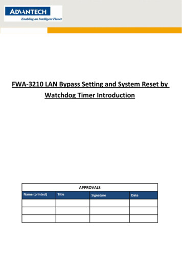
About the unitFamiliarize yourself with the features of the Network Active Bypass unit beforeyou add the unit to your network.Front panel diagramThe following figure illustrates the front panel of the Network Active Bypass unitYour unit's front panel may vary depending on the model:Note: Segments are arranged right-to-left, in the following order: Segment 4,Segment 3, Segment 2, Segment 1.1. Network ports: 1G (SR, LR, or Copper) N1 and N2 ports connecting to anIngress network and Egress network2. Appliance ports: 1G (SR, LR, or Copper) A1 and A2 ports connecting to an IPSappliance3. LCD displayNote: LCD buttons are not active.4. LED indicators (position of LED indicators varies depending on the model)v Link/Active LEDs for 1 G ports: lights indicate if a connection exists and thegeneral amount of trafficv Existing connection– Green indicates a connection– Amber indicates a collision– No light indicates no connectionv Amount of traffic– Rapid blinking indicates heavy traffic– Slow blinking indicates light traffic– No blinking indicates no traffic5. Console port serial6. Management port Ethernet7. Tap portPower adapterYou must use a UL listed power supply with a rated output of 12 VDC, 5 A,marked LPS or NEC Class 2.Chapter 1. Introducing the Network Active Bypass unit3
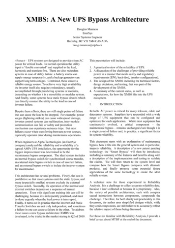
Basic operationThis topic describes the basic operating principles of the Network Active Bypassunit.Typical deploymentThe following diagram shows how the data is transferred from the network to theNetwork IPS through the Network Active Bypass unit, and highlights theassociated functions handled at each stage of bypass switching.Switching modesThe Network Active Bypass unit provides two switching modes:Switching modeDescriptionActiveActive mode channels Ethernet framesbetween the public network and the privatenetwork through the Network IPS appliance.Typically, data flows from the publicnetwork to port N1 (network in). TheNetwork Active Bypass unit transfers thedata to port A1 (appliance in) and thenroutes the data through the Network IPSappliance to port A2 (appliance out). Activeswitching then routes the data through portN2 and out to the private network.Active mode also operates in reverse,routing data from a private network to apublic network.4Network Active Bypass: User Guide
Switching modeDescriptionBypassBypass mode channels Ethernet frames fromthe public network to port N1 (network in).Data is routed through a closed loop fromport N1 (network in) to port N2 (networkout) and bypasses the Network IPSappliance so that frames go directly from thepublic network to the private network.Bypass mode also operates in reverse,routing data from a private network to apublic network.Heartbeat modesThe Network Active Bypass unit can continually monitor the health of NetworkIPS appliances by sending and receiving heartbeat pulses. This ensures real-timesafety and accuracy of the data stream. You use a set time defined in the Timeoutvalue (see “Command line parameters” on page 25 for timeout values) to configureheartbeat frames that are sent from the Network Active Bypass unit on oneappliance port and received on the other port.Network Active Bypass unit provides the following heartbeat modes :Heartbeat modeDescriptionInternal Heartbeat Frame Loopback ModeA user-defined Ethernet heartbeat frame thatis generated by the Network Active Bypassunit. and sent from port A1.The NetworkActive Bypass unit Ethernet port A2 mustreceive the same heartbeat frame from theNetwork IPS appliance.Note: The heartbeat is sent every 100milliseconds (ms) by default and can beincreased up to 25500 ms.This mode is designed for Network IPSappliances that act as a bridge. Make sureappliances are properly configured so thatthe device does not filter out the heartbeatframe. This mode does not require a driverfor Network IPS appliances.Default: 1Link Status Heartbeat ModeThe heartbeat signal acts as a link statusindicator for Network Active Bypass unitEthernet port A1 and A2. If port A1 or portA2 loses the link, theNetwork Active Bypassunit stops the heartbeat transmissions andactivates bypass mode.Chapter 1. Introducing the Network Active Bypass unit5
Operation modesThe Network Active Bypass unit uses the following operation modes:Operation modeDescriptionMode 0: Normal Active InlineThe bypass unit passes traffic to theNetwork IPS appliance.If the unit does not receive a heartbeat, thenit bypasses the Network IPS appliance andforwards the traffic to the network.Mode 1: Normal InlineThe bypass unit passes traffic to thenetwork, bypassing the Network IPSappliance.If the unit does not receive a heartbeat, thenit passes traffic to the Network IPSappliance.Mode 2: Manual Active InlineThe bypass unit always passes traffic to theNetwork IPS appliance, whether it receives aheartbeat or not.Another description for this mode is that thebypass unit always works in ActiveSwitching mode.Mode 3: Manual Active BypassThe bypass unit always passes traffic to thenetwork, bypassing the Network IPSappliance, whether it receives a heartbeat ornot.Another description for this mode is that thebypass unit always works in BypassSwitching mode.This operation mode is useful formaintenance tasks, such as updatingfirmware, installing patches, or replacingappliances.Mode 4: Manual Passive BypassThe bypass unit does not pass any traffic,either to the Network IPS appliance or to thenetwork.This operation mode is useful for testinghigh availability scenarios.6Network Active Bypass: User Guide
Chapter 2. Setting up the Network Active Bypass unitThis chapter contains information you need to connect and configure the NetworkActive Bypass unit.Topics“Configuring and deploying the Proventia Network Active Bypass unit”Configuring and deploying the Proventia Network Active Bypass unitThis topic contains detailed steps for configuring and deploying the NetworkActive Bypass unit.About this taskThe following process is required to configure and deploy the Network ActiveBypass unit.Procedure1. Place the Network Active Bypass unit and the Network IPS appliances on arack.2. Connect the cable to and configure the Network IPS appliances using theinstructions provided in the Proventia GX Getting Started Guide.3. Connect the power cables to the Network Active Bypass unit and to twodifferent power sources (for added redundancy).4. Use a browser to access the management interface and log in.5. Verify that the Network Active Bypass unit is passing traffic.6. Use the management interface to set the segment configuration. (This processmaps the ports on the appliance and sets bypass tolerances.) Copyright IBM Corp. 2009, 20107
Placing the Network Active Bypass unit and the Network IPSappliancesProcedure1. Decide where to place the Network Active Bypass unit and the Network IPSappliances.2. Add the Network Active Bypass unit and the Network IPS appliances to therack.3. Connect the cable to the Network IPS appliances using the instructionsprovided in the Proventia GX Getting Started Guide.Note: The Network Active Bypass unit uses four 1 Gb segments.Connecting the power cablesProcedure1. Plug the DC connector of each AC adapter into the Network Active Bypassunit.2. Plug one of the power cables into an AC outlet. Plug the other power cable intoan AC outlet serviced by a different AC feed.Tip: Use independent AC power sources to maximize power redundancy in theevent of AC power loss from a single source.3. Check the power LEDs to confirm that the Network Active Bypass unit isreceiving power.Logging into the management interfaceProcedure1. Use the management cable (labeled “CAT5E”) to connect a computer to themanagement port on the Network Active Bypass unit.Important: Make sure you follow industry best practices for securing yourcritical network infrastructure. Do not connect the management port to anynetwork that is open to external traffic. The management port should beconnected only to a restricted network that is dedicated to managing theNetwork Active Bypass unit and the Network IPS appliances.2. Start Internet Explorer.3. Type https://192.168.0.111.Note: The default IP address for the management port is 192.168.0.111. If youchange the management port IP address, the Web address to access themanagement port is changed to include the new IP address.4. Log in to the management interface. Use the default user name and passwordthe first time you connect to the management interface.FieldDefault settingUser NameadminPasswordadminNote: If you change the default log on settings on the Users page of themanagement interface, the values you set are in effect for future log onattempts.8Network Active Bypass: User Guide
Setting up e-mail notificationAbout this taskConfigure e-mail notification to receive a status e-mail when the state of theNetwork Active Bypass unit changes. You must set up e-mail notification before youconfigure your segments.Setting up segmentsProcedure1. In the management interface, select theSegment page for the Segment you wantto configure.2. Type or select the appropriate settings, and then click SaveChapter 2. Setting up the Network Active Bypass unit9
10Network Active Bypass: User Guide
Chapter 3. Configuring the Network Active Bypass unit in themanagement interfaceYou can use either the management interface or the command line interface to setmost of the configuration options for the Network Active Bypass unit. This chapterlists the configuration options available through the user interface, and describeshow to set them.Topics“About the management interface” on page 12“Accessing the management interface” on page 13“Monitoring the status of the Network Active Bypass unit” on page 14“Managing settings for the Network Active Bypass unit” on page 15 Copyright IBM Corp. 2009, 201011
About the management interfaceThe Network Active Bypass unit provides a secured Web management interface.Management pagesThe management interface consists of a series of pages, as indicated in thefollowing table:12Management PageDescriptionStatusStatus information about the Network ActiveBypass unitManagement PortIP settings for the management portSegment 1Port settings and heartbeat settings toactivate bypass or get into active mode, forappliances on this segment.Segment 2Port settings and heartbeat settings toactivate bypass or get into active mode, forappliances on this segment.Segment 3Port settings and heartbeat settings toactivate bypass or get into active mode, forappliances on this segment.Segment 4Port settings and heartbeat settings toactivate bypass or get into active mode, forappliances on this segment.Email NotificationsSettings required for e-mail notification, suchas e-mail accounts and mail serverinformationSNMP SettingsSettings for sending SNMP traps to anSNMP trap serverNTP SettingsSettings that enable the network timeprotocol (NTP) to synchronize the NetworkActive Bypass unit time with a network timeserverTime SettingsTime zone settings for the Network ActiveBypass unitBackup/RestoreBackup, restore, and reset to factory defaultfunctionsFirmware UpdateUpload firmware update files to theNetwork Active Bypass unitLog SettingsSettings for the system log filesRebootReboot the Network Active Bypass unitUsersChange the admin passwordRemote AuthenticationSettings that allow a remote access server tocommunicate with an authentication serverin order to determine if the user has accessto the networkNetwork Active Bypass: User Guide
Accessing the management interfaceYou can manage and monitor the Network Active Bypass unit from any Webbrowser.PrerequisiteMake sure that the Ethernet management port for the Network Active Bypass unitis connected to the local network or to the host computer.Default management port IP address and Web addressThe Network Active Bypass unit has a default IP address assigned to themanagement port. The default IP address and URL are shown in the followingtable:ItemDefault valueManagement port IP address192.168.0.111Management port Web addresshttps://192.168.0.111These default values remain in effect until you change them. You can usecommand line parameters or use the Management Port page of the managementinterface to change the the IP address for the management port.Important: Changes to the management port can interrupt the managementinterface connection. Make sure that the new IP address is accessible before youmake any changes. When you change the IP address, the management port Webaddress changes also.Management interface Web addressYou can access the management interface using a Web address that consists ofhttps:// followed by the management port's IP address. The Web address format isas follows:https://xxx.xxx.xxx.xxxWhen you type the Web address, replace xxx.xxx.xxx.xxx with the IP addressassigned to the management port.For example, the default Web address is https://192.168.0.111Note: When you enter the Web address, you will see a message regarding the Website's security certificate. Click “Continue to this website (not recommended)” toproceed.Logging inWhen you enter the management Web site, you see the log in screen. Complete thefields as indicated in the following table.FieldDescriptionUserType the user nameNote: The default user is admin.Chapter 3. Configuring the Network Active Bypass unit in the management interface13
FieldDescriptionPasswordType the passwordNote: The default password is admin.The default values remain in effect until you change them. If you need to changethe user name or password, you can use the Users page of the managementinterface or the command line interface.Monitoring the status of the Network Active Bypass unitThis topic provides information about using the management interface to monitorthe status of the Network Active Bypass unit.Checking overall statusThe Status page is the first page you see when you log in to the managementinterface. Use the Status page to view information for the Network Active Bypassunit. The Status page provides information in sections, as indicated in thefollowing table.SectionDescriptionSystemProvides general information about theNetwork Active Bypass unitPower SupplyIndicates whether power supplies arepresent or not presentSegment 1Shows the active/bypass status for segment1Segment 2Shows the active/bypass status for segment2Segment 3Shows the active/bypass status for segment3Segment 4Shows the active/bypass status for segment4Tap SettingsShows current port configurationsViewing system statusThe System section provides general system status, as indicated in the followingtable.FieldDescriptionProduct NameDisplays the name of the Network ActiveBypass unit:“Proventia NAB”Product IDDisplays the product ID of the NetworkActive Bypass unit:“Proventia NAB rev 1”14Hardware RevisionDisplays the hardware version of theNetwork Active Bypass unitFirmware VersionDisplays the current firmware version of theNetwork Active Bypass unitNetwork Active Bypass: User Guide
FieldDescriptionManagement IPDisplays the IP address for the managementportTip: Use the Management Port page if youwant to change IP settings for themanagement port.Default: 192.168.0.111Email NotificationsIndicates whether e-mail notifications areenabled or disabledTip: Use the Email Notification page if youwant to change e-mail settings.Default: Disable (Don't send)Managing settings for the Network Active Bypass unitUse the management interface to view or change settings for the Network ActiveBypass unit.Setting up segment configurationsProcedure1. In the management interface, select the Segment Configuration page.2. Complete the fields for each of the four segments (A - D) that best fits yourspecific network environment:FieldDescriptionMax time allowed between heartbeatacceptance (100 ms - 25500 ms)Specifies the user-defined Ethernet heartbeatframe generated by the Network ActiveBypass unit.The heartbeat frames are sent from theNetwork Active Bypass unit Ethernet portA1 every 100 milliseconds (ms), and theNetwork Active Bypass unit Ethernet portA2 must receive the same heartbeat framefrom the Network IPS appliance.Number of HB lost to activate bypass(1–10)Specifies the heartbeat signal that acts as alink up status indicator for the NetworkActive Bypass unit Ethernet ports A1 andA2.If port A1 or A2 loses the link, NetworkActive Bypass unit stops the heartbeattransmission and activates bypass mode.Number of accepted HB to get into activemode (1–10)Specifies the user-defined Ethernet heartbeatframe that is generated by the Network IPSappliance. This is the number of heartbeatsthe Network Active Bypass unit mustreceive in order for the unit to change frombypass to active.Default: 1Chapter 3. Configuring the Network Active Bypass unit in the management interface15
FieldDescriptionOperation ModeSpecifies the operation mode of the NetworkActive Bypass unit:v Mode 0: Normal Active Bypass (Defaultmode) - If Network Active Bypass unitreceives heartbeat signals within theTimeout period, the switching moderemains or is changed to Active Switchingmode.If Network Active Bypass unit does notreceive heartbeat signals within theTimeout period, it will change to orremain in Bypass Switching mode.By default (without a heartbeat), NetworkActive Bypass unit remains in BypassSwitching mode.v Mode 1: Normal Active Inline - IfNetwork Active Bypass unit receivesheartbeat signals within the Timeoutperiod, the switching mode remains or ischanged to Bypass Switching mode.If Network Active Bypass unit does notreceive heartbeat signals within theTimeout period, it will change to orremain in Active Switching mode.By default (without a heartbeat), NetworkActive Bypass unit remains in ActiveSwitching mode.v Mode 2: Manual Active - Network ActiveBypass unit is always in Active Switchingmode.v Mode 3: Manual Active Bypass - NetworkActive Bypass unit is always in BypassSwitching mode.v Mode 4: Manual Passive Bypass Network Active Bypass unit is in passivebypass, in which the optical switch is“Close” in bypass mode.Link fault detectionGenerates an SNMP trap if a network portstops functioning:v 0: disables the system from detecting LinkFault Detectionv 1: enables the system to detect andactivate Link Fault DetectionDefault: Enabled16Network Active Bypass: User Guide
FieldDescriptionTap SettingSpecifies the ports on the Network ActiveBypass unit for data flow during BypassSwitching mode and Active Switching mode:v Port N1: Network inv Port N2: Network outv Port A1: Appliance inv Port A2: Appliance outOptions for Tap setting are:v RXv TXv RX/TXConfiguring Management Port settingsProcedureUse the Management Port page to configure IP settings for the management port.FieldDescriptionIP AddressIP address of the management portDefault: 192.168.0.111Network MaskIP address of the network or subnet maskDefault: 255.255.255.0GatewayIP address of the network gatewayDefault: 192.168.0.1DNS 1IP address of the primary domain namesystem serverDefault: 192.168.0.1DNS 2IP address of the secondary domain namesystem serverDefault: 0.0.0.0Chapter 3. Configuring the Network Active Bypass unit in the management interface17
Setting up e-mail notificationsAbout this taskTheNetwork Active Bypass unit provides an e-mail notification function that youcan configure to send an e-mail message when the switching mode of a segmenthas changed. Use the Email Notification page to configure e-mail servers andaccounts, and to enable or disable notifications.ProcedureSet the values as indicated in the following table.FieldDescriptionEmail NotificationEnable or disable e-mail notificationDefault: Disabled (Don't send)Outgoing Mail Server (SMTP)Address of the appropriate outgoing SMTPmail serverOutgoing Mail Server (SMTP) PortPort number of the outgoing SMTP mailserverDefault: 25SMTP UsernameUser name for the outgoing SMTP mailserverSMTP PasswordPassword for the outgoing SMTP mail server(if applicable)Outgoing Server (SMTP) SecuritySSL encryption used between the SMTP mailserver and mail clientDefault: Enable (Secured)From (Sender's email address)Name or address that should be displayedin the From field of an outgoing e-mailmessageTo (List of recipients, comma separated)List of e-mail addresses to whom thenotification should be sentSubjectSubject to be displayed in the subject line ofthe outgoing e-mail messageExample: “Proventia NAB status report”18Network Active Bypass: User Guide
Configuring SNMP trapsAbout this taskThe Network Active Bypass unit provides an SNMP trap function that can sendmessages to a trap server when the segment status or power supply statuschanges. Use the SNMP Settings page to configure the SNMP destination IP andSNMPv2 community name, and to enable or disable the SNMP trap function.ProcedureComplete the fields as indicated in the following table.FieldDescriptionSend SNMP TrapsEnable or disable the sending of SNMP trapsDefault: DisabledSNMP traps destination IPDestination IP of the SNMP trap serverDefault: localhostSNMPv2 communityCommunity name of the SNMP trap serverDefault: publicSynchronizing time and setting time zonesProcedureUse the NTP Setting page to enable the network time protocol (NTP) tosynchronize the Network Active Bypass unit time with a network time server. Usethe Time Setting page to set the time zone for the Network Active Bypass unit. Setthe values as described in the following table.FieldDescriptionNTPProtocol that synchronizes the NetworkActive Bypass unit time with a network timeserverDefault: DisabledNTP ServerPublic domain of a collection of computersthat provide time using NTPTime ZoneTime zone used by the Network ActiveBypass unitDefault: America\New YorkChapter 3. Configuring the Network
Network Active Bypass unit provides the following heartbeat modes : Heartbeat mode Description Internal Heartbeat Frame Loopback Mode A user-defined Ethernet heartbeat frame that is generated by the Network Active Bypass unit. and sent from port A1.The Network Active Bypass unit Ethernet port A2 must receive the same heartbeat frame from the