Transcription
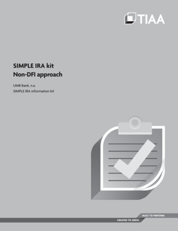
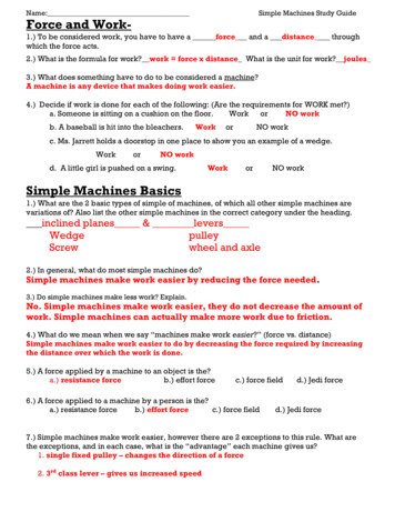
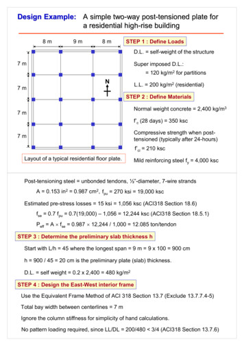
Design Example: A simple two-way post-tensioned plate fora residential high-rise building8m9m8mSTEP 1 : Define LoadsD.L. self-weight of the structure7mSuper imposed D.L.: 120 kg/m2 for partitionsNL.L. 200 kg/m2 (residential)7mSTEP 2 : Define MaterialsNormal weight concrete 2,400 kg/m37mf’c (28 days) 350 kscCompressive strength when posttensioned (typically after 24-hours)7mf’ci 210 kscLayout of a typical residential floor plate.Mild reinforcing steel fy 4,000 kscPost-tensioning steel unbonded tendons, ½”-diameter, 7-wire strandsA 0.153 in2 0.987 cm2, fpu 270 ksi 19,000 kscEstimated pre-stress losses 15 ksi 1,056 ksc (ACI318 Section 18.6)fse 0.7 fpu 0.7(19,000) – 1,056 12,244 ksc (ACI318 Section 18.5.1)Peff A fse 0.987 12,244 / 1,000 12.085 ton/tendonSTEP 3 : Determine the preliminary slab thickness hStart with L/h 45 where the longest span 9 m 9 x 100 900 cmh 900 / 45 20 cm is the preliminary plate (slab) thickness.D.L. self weight 0.2 x 2,400 480 kg/m2STEP 4 : Design the East-West interior frameUse the Equivalent Frame Method of ACI 318 Section 13.7 (Exclude 13.7.7.4-5)Total bay width between centerlines 7 mIgnore the column stiffness for simplicity of hand calculations.No pattern loading required, since LL/DL 200/480 3/4 (ACI318 Section 13.7.6)
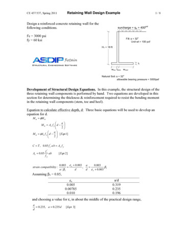
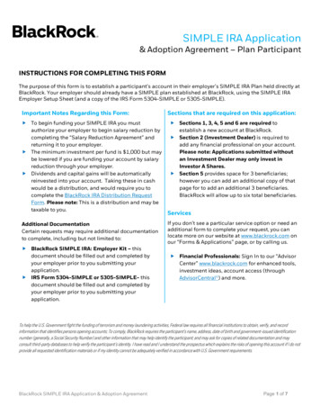
STEP 5 : Section PropertiesTwo-way plate must be designed as class U (ACI 318 Section 18.3.3).The gross sectional properties are allowed (ACI 318 Section 18.3.4).0.2 mA bh (700 cm)(20 cm) 14,000 cm2S bh2/6 (700 cm)(20 cm)2 / 6 46,667 cm37mSTEP 6 : Design ParametersAllowable stresses: Class U (ACI 318 Section 18.3.3)Strength at time of jacking f’ci 210 kscCompression 0.60 f’ci 0.6 (210 ksc) 126 kscTension 0.795 f’ci 0.795 (210)0.5 11.5 kscAt service loads (ACI 318 Section 18.4.2(a) and 18.3.3)Compressive strength f’c 350 kscCompression 0.45 f’c 0.45 (350 ksc) 158 kscTension 1.59 f’ci 1.59 (350)0.5 29.8 kscAverage pre-compression limits (ACI 318 Section 18.12.4)P / A 8.8 ksc minimum to 21 ksc maximumTarget load balances, use 60% - 80% of DL (self-weight) for plateFor this example: 0.75 DL 0.75 (480) 360 kg/m2STEP 7 : Tendon ProfileUse the parabolic shape. For a layout with spans of similar length, thetendons will be typically located at the highest allowable point at theinterior columns, the lowest possible point at the mid-spans, and at theneutral axis at the anchor locations. This provides the maximum drapefor load-balancing.The continuous post-tensioned beam.
The continuous post-tensioned beam.Tendon OrdinateTendon (CG) Location*Exterior support - anchor10 cmInterior support - top17.5 cmInterior span - bottom2.5 cmEnd span - bottom4.5 cm(CG) means center of gravity, *Means measured from slab bottomaINT 17.5 – 2.5 15 cmaEND (10 17.5)/2 – 4.5 9.25 cmSTEP 8 : Prestress force P required to balance 75% DLwb 0.75 wDL 0.75 (480 kg/m2) (7 m) / 1,000 2.52 t/mSince the spans are similar length, the end span will typically govern the maximumrequired post-tensioning force.This is due to the significantly reduced tendon drape, aEND.The force P needed in the tendons to counteract the load in the end bay is,P (wb L2 / 8) / aEND (2.52 82 /8) / 0.0925 218 tonsSTEP 9 : Check pre-compression allowanceDetermine the number of tendons required to attain the 218 tons,Number of tendons (218 tons) / (12.085 tons/tendon) 18.04USE 18 tendonsActual force for banded tendons (18 tendons) (12.085 tons) 217.5 tonsThe balanced load for the end span is slightly adjusted,wb (217.5 / 218) (2.52 t/m) 2.51 t/m
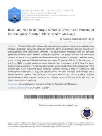
Determine the actual pre-compression stress in the slab,Pactual / A (217.5 x 1,000) / (14,000 cm2) 15.5 ksc ( 8.8 ksc minimum and 21 ksc maximum) OKSTEP 10 : Check the interior span force PP (wb L2 / 8) / aINT (2.52 92 /8) / 0.15 170 tons 217.5 tonsTherefore, a smaller force is required in the center bay.For this example, continue the force required for the end spans into the interior spanand check the amount of load that will be balanced:wb 217.5 8 0.15 / 92 3.22 t/mTherefore, wb / wDL 3.22 / 3.36 96% 100% OKTherefore, for the East-West interior frame:Effective prestress force, Peff 217.5 tonsSTEP 11 : ก ก ก ก ก ก ก ก ! ก "# % &' ! ก%() Dead Load Moments:wDL (480 120)(7 m) / 1,000 4.2 t/m4.2 t/m8m9m20.0 t-m8m20.0 t-m12.2 t-m-30.3 t-m-30.3 t-m
Live Load Moments:wLL (200)(7 m) / 1,000 1.4 t/m1.4 t/m8m9m8m6.68 t-m6.68 t-m4.08 t-m-10.1 t-m-10.1 t-mTotal Balancing Moments, Mbal :wb 2.75 t/m (average of 3 bays)2.75 t/m8m9m19.8 t-m8m19.8 t-m-8.01 t-m-13.1 t-m-13.1 t-m
STEP 12 Stage 1 : Stresses immediately after jacking (DL PT)Mid-span stresses,ACI 318 18.4.1ftop (-MDL Mbal)/S – P/Afbot ( MDL - Mbal)/S – P/AInterior Span:ftop (-12.2 8.01)(100)(1,000)/46,667 – 15.5 ksc -9.0 – 15.5 -24.5 ksc compression 0.60f’ci 126 kscOKfbot ( 12.2 - 8.01)(100)(1,000)/46,667 – 15.5 ksc 9.0 – 15.5 -6.5 ksccompression 0.60f’ci 126 kscOKEnd Span:ftop (-20.0 13.1)(100)(1,000)/46,667 – 15.5 ksc -14.8 – 15.5 -30.3 ksc compression 0.60f’ci 126 kscOKfbot ( 20.0 – 13.1)(100)(1,000)/46,667 – 15.5 ksc 14.8 – 15.5 -0.2 ksc compression 0.60f’ci 126 kscSupport stresses,OKftop ( MDL - Mbal)/S – P/Afbot (-MDL Mbal)/S – P/Aftop (30.3 – 19.8)(100)(1,000)/46,667 – 15.5 ksc 22.5 – 15.5 7.0 ksctension 0.8 f’ci 11.6 kscOKfbot (-30.3 19.8)(100)(1,000)/46,667 – 15.5 ksc -22.5 – 15.5 -38 ksc compression 0.60f’ci 126 kscOK
Stage 2 : Stresses at service load (DL LL PT)Mid-span stresses,ACI 318 18.3.3 & 18.4.2ftop (-MDL - MLL Mbal)/S – P/Afbot ( MDL MLL - Mbal)/S – P/AInterior Span:ftop (-12.2 – 4.08 8.01)(100)(1,000)/46,667 – 15.5 ksc -17.7 – 15.5 -33.2 ksc compression 0.45f’c 157.5 kscOKfbot ( 12.2 4.08 - 8.01)(100)(1,000)/46,667 – 15.5 ksc 17.7 – 15.5 2.2 ksc tension 1.6 f’c 29.9 kscOKEnd Span:ftop (-20.0 – 6.68 13.1)(100)(1,000)/46,667 – 15.5 ksc -29.1 – 15.5 -44.6 ksc compression 0.45f’c 157.5 kscOKfbot ( 20.0 6.68 – 13.1)(100)(1,000)/46,667 – 15.5 ksc 29.1 – 15.5 13.6 ksc tension 1.6 f’c 29.9 kscSupport stresses,OKftop (MDL MLL - Mbal)/S – P/Afbot (-MDL - MLL Mbal)/S – P/Aftop (30.3 10.1 – 19.8)(100)(1,000)/46,667 – 15.5 ksc 44.1 – 15.5 28.6 ksc tension 1.6 f’c 29.9 kscOKfbot (-30.3 – 10.1 19.8)(100)(1,000)/46,667 – 15.5 ksc -44.1 – 15.5 -59.6 ksc compression 0.45f’c 157.5 kscAll stresses are within the permissible code limits.OK
STEP 13 : Determine the factored momentsPrimary post-tensioning moments Mprim vary along the length of spanMprim P ewhere e 0 cm at exterior support ande 7.5 cm at interior supportMprim 217.5 7.5 / 100 16.3 t-mSecondary post-tensioning moments Msec vary linearly between supportsMsec Mbal – Mprim 19.8 – 16.3 3.5 t-m at interior supports3.5 t-mLoad combination :3.5 t-mMu 1.4 MDL 1.7 MLL 1.0 MsecAt midspan, Mu 1.4(20.0) 1.7(6.68) 1.0(1.75) 41.1 t-mAt support, Mu 1.4(-30.3) 1.7(-10.1) 1.0(3.5) -56.1 t-mSTEP 14 : Determine minimum bonded reinforcementPositive moment region:Interior span: ft 2.2 ksc 0.53 f’c 0.53 350 9.92 kscNo positive reinforcement is required (ACI 318 18.9.3.1)Exterior span: ft 13.6 ksc 0.53 f’c 0.53 350 9.92 kscMinimum positive reinforcement is required (ACI 318 18.9.3.2)y ft / (ft fc) h [13.6 / (13.6 44.6)](20 cm) 4.67 cmNc MDL LL / S 0.5 y L2 [(20.0 6.68)(100)/46,667](0.5)(4.67)(700) 93.5 tonsAs,min Nc / 0.5 fy (93.5 1,000) / [0.5(4,000 ksc)] 46.75 cm2% *กก ! ! ก ) &' 7 %ก ) , -0.2 mAs,min (46.75 cm2) / (7 m) 6.68 cm2 / mUSE DB16 @ 0.30 m at bottom 6.70 cm2/m7m
Negative moment region:As,min 0.00075 Acf (as per ACI 318 18.9.3.3)At interior support:Acf max of (20 cm)[(9 m 8 m)/2 or 7 m](100) 14,000 cm2As,min 0.00075 (14,000 cm2) 10.5 cm2USE 10 DB12 at the top (11.31 cm2)At exterior support:Acf max of (20 cm)[(8 m)/2 or 7 m](100) 8,000 cm2As,min 0.00075 (8,000 cm2) 6.0 cm2USE 6 DB12 at the top (6.79 cm2)STEP 15 : Check minimum reinforcement to see if it is sufficient forultimate strengthMn (As fy Aps fps) (d – a/2)Aps 0.987 cm2 (18 tendons) 17.77 cm2fps fse 704 f’cbd / (300Aps) for slabs with L/h 35 (Sec.18.7.2) 12,244 704 [(350 ksc)(700 cm) d ] / (300 17.77) 12,948 46 da (As fy Aps fps) / (0.85 f’c b)At supports: d 17.5 cmfps 12,948 46 (17.5) 13,753 ksca [(11.31 cm2)(4,000 ksc) (17.77 cm2)(13,753 ksc)] / (0.85 350 700) 1.39 cm
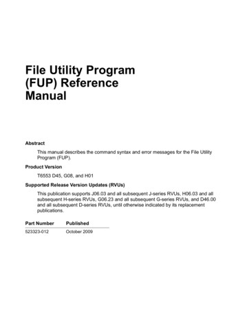
Mn (As fy Aps fps) (d – a/2) [(11.31 cm2)(4,000 ksc) (17.77 cm2)(13,753 ksc)] (17.5 – 1.39/2) 4,867,246 kg-cm 48.67 t-mφMn 0.9 (48.67) 43.8 t-m [ Mu 56.1 t-m ]NGTherefore, reinforcement for ultimate strength requirements governs.Try As,reqd (56.1 / 43.8) (11.31) 14.47 cm2USE 30 DB12 (33.9 cm2)a [(33.9 cm2)(4,000 ksc) (17.77 cm2)(13,753 ksc)] / (0.85 350 700) 1.83 cmMn [(33.9 cm2)(4,000 ksc) (17.77 cm2)(13,753 ksc)] (17.5 – 1.83/2) 6,302,148 kg-cm 63.02 t-mφMn 0.9 (63.02) 56.7 t-m [ Mu 56.1 t-m ]OKFinal PT Layout8m9m8m7m7m7m7mN
8mSTEP 15 : Check Punching ShearInterior column : 40 cm x 40 cm9m7mTributary area (7 m) (8 m 9 m) / 2 59.5 m2At supports: d 17.5 cm7mShear area (0.4 0.175) x (0.4 0.175) 0.33 m2wu 1.4 (480 120) 1.7 (200) 1,180 kg/m2Vu (1,180 kg/m2) (59.5 m2 – 0.33 m2) / 1,000 69.8 tonsVc 1.06 fc′ b0 d 1.06 350 (4)(40 17.5)(17.5) /1,000 79.8 tons [ Vu/φ 69.8/0.85 82.1 tons ]Need Punching Shear ReinforcementNG
Compressive strength when post-tensioned (typically after 24-hours) Mild reinforcing steel fy 4,000 ksc f'ci 210 ksc N STEP 3 : Determine the preliminary slab thickness h Post-tensioning steel unbondedtendons, ½"-diameter, 7-wire strands A 0.153 in 2 0.987 cm 2, f pu 270 ksi 19,000 ksc fse 0.7 fpu Peff A fse