Transcription
TEST REPORT ONCENTRAL STATES MANUFACTURING, INC.’SPANEL-LOC PLUS PANELS(29 GA., 80 KSI, 36" WIDE)FASTENED TO WOOD SUPPORTSAT 2' 0" & 3' 0" PANEL SPANSIN ACCORDANCE WITH ASTM E455-11AND AISI S907-08TESTED FOR:Central States Manufacturing, Inc.302 Jane PlaceLowell, AR 72745Telephone: (800) 356-2733Fax: (800) 356-2971TESTED BY:ENCON Technology, Inc.1216 North Lansing Avenue, Suite CTulsa, OK 74106Telephone: (918) 492-5992FAX: (866) 366-1543TEST WITNESSED BY:Bala Sockalingam, Ph.D., P.E.TESTING DATE: January 16 & 18, 2013REPORTING DATE: January 29, 2013ENCON Project C1877-1TL-327
TABLE OF CONTENTSSECTION ITEST SUMMARYPage Number1.1 Summary1.2 Panel System Description1.3 Test Results1.4 Panel and Fastener Pattern DrawingSECTION II1112DESCRIPTION OF TEST2.1 Description of Test2.2 Calculations3-44-5SECTION III TEST RESULTS3.1 Specimen Identification3.2 Test #1: Panel-Loc Plus Panels at four equal span of 2' 0"3.3 Test #2: Panel-Loc Plus Panels at four equal span of 2' 0"3.4 Test #3: Panel-Loc Plus Panels at three equal span of 3' 0"67-89-1011-12SECTION IV TEST PHOTOGRAPHS4.1SECTION VTest Photographs13-16APPENDIX5.1 Test Drawings5.2 Yield Stress5.3 Test ConditionsENCON Technology Inc.C1877-117-222324-251/29/2013
TEST SUMMARY1.1 SUMMARYTests were conducted on Central States Manufacturing, Inc.’s 29 ga., 80 ksi Panel-Loc Pluspanels at ENCON Technology, Inc.’s Test Facility, Tulsa, Oklahoma. The purpose of the testswas to determine the diaphragm shear strength and shear stiffness of Panel-Loc Plus panelconstruction under simulated loading conditions. These tests meet the provisions of ASTME455-11 and AISI S907-08. The tests are listed below according to date tested.Test #1 & 2: Panel-Loc Plus panels at four equal spans of 2' 0". The structural fastener spacingwas 9" o.c. at the end and interior wood supports. Both tests were conducted onJanuary 16, 2013.Test #3:Panel-Loc Plus panels at three equal spans of 3' 0". The structural fastener spacingwas 9" o.c. at the end and interior wood supports. This test was conducted onJanuary 18, 2013.The sidelap fasteners spacing for all tests was 24" o.c. The above-defined tests were witnessedby Bala Sockalingam, Ph.D., P.E. of ENCON Technology, Inc.1.2PANEL SYSTEM DESCRIPTIONCentral States Mfg.’s Panel-Loc Plus panels were 29 ga., 3/4" high and 36" wide throughfastened panels. Each panel consisted of five major ribs spaced at 9" o.c. as shown on Page 2.The panels were fastened to nominal 2" x 6" SPF wood supports with #10 x 1-1/2" longKwikseal II Wood Binder screws with washers. The screw spacing was 9" o.c. at the end andinterior wood supports. Each panel spanned over four continuous spans of 2' 0" or threecontinuous spans of 3' 0" with 2" overhang. The sidelap fasteners were #12 x 3/4" long hex headstitch screws with washers and spaced at 24" o.c. The two sides of the panel assembly were notattached to the side post of the interior frame.1.3TEST RESULTSLoad was applied incrementally and deflections of the test construction were recorded for ‘noload’ condition and at each load increment. The failure mode in Test #1 & #2 was the panelslotting at fasteners near the roller and pinned corners. The average ultimate shear strength fromthe two test constructions was 291.7 lb/ft and average shear stiffness was 8383.5 lb/in.The failure mode in Test #3 was the panel buckling near the loaded corner. The ultimate shearstrength was 183.3 lb/ft and shear stiffness was 8145.2 lb/in.ENCON Technology Inc.C1877-1Page 1/251/29/2013
DESCRIPTION OF TEST2.1 DESCRIPTION OF TESTOBJECTIVESTests were conducted to determine shear strength and shear stiffness of the panels undersimulated loading conditions. The test method consisted of the following:1.2.3.assembling the test panel on an interior test frame to form a typical roof or wallconstruction;loading the test frame incrementally; andobserving, measuring, and recording the deflections, deformations, and nature of anyfailures of principal or critical elements of the test construction.The increments of load application were chosen such that a sufficient number of readings wereobtained to determine the load deformation curve of the system.TEST SETUPThe test setup consisted of an exterior reaction truss and interior panel support frame as shown inthe applicable drawings in the appendix. The L-shaped reaction truss was constructed of twobuilt-up tube sections with cross-braced angle sections to form a truss. The panel support framewas constructed of wood supports having equal or lower strength and stiffness than that intendedfor use in the typical constructions. All the connections in the interior frame were pinned.Both the truss and frame lay in the same horizontal plane. The reaction frame was supported byshort columns, which rested on the laboratory floor. Two corners of the interior frame wereconnected to the exterior frame with a hinge and roller. The side opposite to these corners washeld up by columns with roller bases. The interior supports were attached to the side post withpinned connections.LOADING DEVICELoad was applied using a 10 kip capacity hydraulic ram and manual pump. The load wasmonitored with a calibrated 10 kip capacity load cell and associated instrumentation. Theaccuracy of the load cell was estimated to be 0.01 kips. The hydraulic ram was attached to thereaction truss and the load cell was attached to the interior frame. The load was applied parallelto and in close proximity to one of the points of contact between the diaphragm web and frame.DEFLECTION MEASUREMENTDeflection measurements were taken by means of dial indicators calibrated to 1/1000 of an inch.Deflections were measured at locations as shown on the drawings in the appendix. Thedeflection locations are based on AISI S907-08.ENCON Technology Inc.C1877-1Page 3/251/29/2013
DESCRIPTION OF TESTDIAPHRAGM SIZEThe overall dimension of each construction was in excess of 12' x 8' 4" or 9' 4". The panelscovered four equal spans of 2' 0" or three equal spans of 3' 0". The construction width containedfour full panels. The panels were attached to the end and interior wood supports with selfdrilling screws. The panels were not attached to the side member of the interior frame. Thedetails of the methods of construction are depicted in the enclosed test drawings. All thematerial used in the construction represented a typical construction.NUMBER OF TESTSMinimum of two panel assemblies was tested for panel span of 2' 0" to determine the shearstrength and stiffness. As per Section 8.2 of ASTM E455, the duplicate test for panel span of 3'0" was waived due to testing span variability.TEST PROCEDUREPrior to the diaphragm construction, the interior frame was loaded to determine its bare framestiffness. The bare frame stiffness was insignificant, deflecting 1" under a 10-lb load. Theloading procedure on the completed diaphragm construction consisted of loads applied inincrements. The diaphragm was loaded to 20% of the anticipated ultimate load and unloaded.Deflection measurements were recorded at ‘no load’ conditions. The diaphragm was loaded in250-lb increments until failure for Test #1 & #2 and in 200-lb increments until failure for Test#3. Deflection measurements were recorded at every load increment.TEST DURATIONThe test was stopped when the test specimen was unable to carry additional load or visual failureof one or more components of the diaphragm occurred.2.2 CALCULATIONSThe ultimate shear strength Su (lb/ft) of a given construction iswherePSu ubPu maximum applied load in the cantilever beam test (lb),b depth of diaphragm (ft).The net shear deflections ( ) at any load level in the cantilever beam test is 3 2 b 1 4 a where 1, 2, 3 and 4 are measured deformations with appropriate signs at locations shown inthe test drawings.ENCON Technology Inc.C1877-1Page 4/251/29/2013
DESCRIPTION OF TESTThe apparent shear stiffness G’ (lb/in) of a given construction isG P a b whereP 0.4Pu in the cantilever beam test (lb),a span of diaphragm (ft). Net shear deflection of diaphragm (in) at 0.4Pu load.The shear stiffness calculation is based on AISI S907-08.ENCON Technology Inc.C1877-1Page 5/251/29/2013
TEST RESULTS3.1 SPECIMEN IDENTIFICATIONManufacturer:Central States Manufacturing, IncModel Type:Panel-Loc Plus PanelDimensions:0.75" high, 36" wide coveragePanel Thickness:29 ga.Base Metal Thickness:0.0136"Panel Yield Stress:80 ksi (100 ksi tested)Panel Fasteners:#10 x 1.5" long hex head wood screws with washers (SealtiteBuilding Fasteners Kwikseal II Wood Binder)Panel Fasteners Spacing:9" o.c.Support Thickness:Nom. 2" x 6" SPFSidelap Fasteners:#12 x 3/4" long hex head stitch screws with washers (SealtiteBuilding Fasteners)Sidelap Fasteners Spacing:24" o.c.Note:All the test materials were supplied by or purchased for Central StatesManufacturing and were not sampled by ENCON.ENCON Technology Inc.C1877-1Page 6/251/29/2013
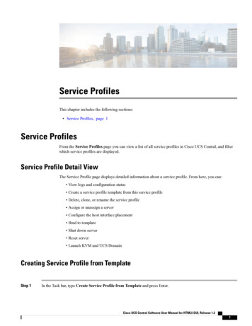
TEST RESULTS3.2 TEST #1: 29 GA. PANEL-LOC PLUS AT FOUR EQUAL SPAN OF 2' 0"Test No:Date:Panel Type:Gauge:Thickness:Panel Width:Support Spacing:Type of Structural Fastener:Fastener Spacing at End Supports:Fastener Spacing at Interior Supports:InsulationType of Sidelap Fastener:Sidelap Fastener Spacinga span length of diaphragm (ft):b depth of diaphragm (ft):Dial Indicator Reading 275030003250350011.16.13Panel-Loc Plus29 ga.0.0136"36"4 spans @ 24" o.c.#10 x 1.5" long Kwikseal II screws9" o.c.9" o.c.None#12 x 3/4" long stitch screws24" 1070.1170.1360.1660.2040.2270.2580.318Failure Mode:Duration of test:At construction:At testingENCON Technology ation .2400.2900.3630.4720.6340.865Panel slotting at the fastener near roller and pinned corners 10 minutesTemperature (F)6666.2Page 7/25Relative Humidity (%)26261/29/2013
TEST RESULTSLoad vs Deflection (Test #1)400035003000Load 1.000Deflections (in)ENCON Technology Inc.C1877-1Page 8/251/29/2013
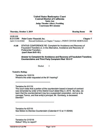
TEST RESULTS3.3 TEST #2: 29 GA., 80 KSI PANEL-LOC PLUS AT FOUR EQUAL SPAN OF 2' 0"Test No:Date:Panel Type:Gauge:Thickness:Panel Width:Support Spacing:Type of Structural Fastener:Fastener Spacing at End Supports:Fastener Spacing at Interior Supports:InsulationType of Sidelap Fastener:Sidelap Fastener Spacinga span length of diaphragm (ft):b depth of diaphragm 0275030003250350021.16.13Panel-Loc Plus29 ga.0.0136"36"4 spans @ 24" o.c.#10 x 1.5" long Kwikseal II screws9" o.c.9" o.c.None#12 x 3/4" long stitch screws24" o.c8.3312.00Dial Indicator Reading 0.1110.1140.1200.1220.1330.142Failure Mode:Duration of test:At construction:At testingENCON Technology mation .2950.3740.4860.6310.8070.976Panel slotting at the fastener near roller and pinned corners 10 minutesTemperature (F)66.266.2Page 9/25Relative Humidity (%)26261/29/2013
TEST RESULTSLoad vs Deflection (Test #2)400035003000Load 1.000Deflections (in)ENCON Technology Inc.C1877-1Page 10/251/29/2013
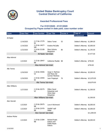
TEST RESULTS3.4 TEST #3: 29 GA., 80 KSI PANEL-LOC PLUS AT THREE EQUAL SPAN OF 3' 0"Test No:Date:Panel Type:Gauge:Thickness:Panel Width:Support Spacing:Type of Structural Fastener:Fastener Spacing at End Supports:Fastener Spacing at Interior Supports:InsulationType of Sidelap Fastener:Sidelap Fastener Spacinga span length of diaphragm (ft):b depth of diaphragm 220031.18.13Panel-Loc Plus29 ga.0.0136"36"3 spans @ 36" o.c.#10 x 1.5" long Kwikseal II screws9" o.c.9" o.c.None#12 x 3/4" long stitch screws24" o.c9.3312.00Dial Indicator Reading 0.1400.1460.173Failure Mode:Duration of test:At construction:At testingENCON Technology eformation .2800.4020.536Panel buckled near load corner 10 minutesTemperature (F)Relative Humidity (%)662766.227Page 11/251/29/2013
TEST RESULTSLoad vs Deflection (Test #3)25002000Load 00Deflections (in)ENCON Technology Inc.C1877-1Page 12/251/29/2013
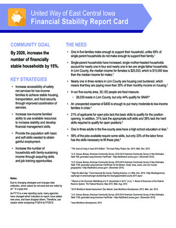
PHOTOGRAPHSPHOTO 1View of the structural and sidelap fasteners.(DSCN0005)PHOTO 2View of the wood support layout for panel span of 2' 0".(DSCN0009)ENCON Technology Inc.C1877-1Page 13/251/29/2013
PHOTOGRAPHSPHOTO 3View of the panel fasteners at end and interior supports.(DSCN0011)PHOTO 4Overview of the diaphragm test setup of the Panel-Loc Plus at 2' 0" span.(DSCN0010)ENCON Technology Inc.C1877-1Page 14/251/29/2013
PHOTOGRAPHSPHOTO 5View of panel slotting at fastener near the roller support in Test #1.(DSCN0015)PHOTO 6View of panel slotting at fastener near the pinned support in Test #2.(DSCN0021)ENCON Technology Inc.C1877-1Page 15/251/29/2013
PHOTOGRAPHSPHOTO 7Overview of the diaphragm test setup of Panel-Loc Plus at 3' 0" span.(DSCN0027)PHOTO 8View of panel buckling near the loaded corner in Test #3.(DSCN0030)ENCON Technology Inc.C1877-1Page 16/251/29/2013
West
(29 GA., 80 KSI, 36" WIDE) FASTENED TO WOOD SUPPORTS AT 2' 0" & 3' 0" PANEL SPANS IN ACCORDANCE WITH ASTM E455-11 AND AISI S907-08 TESTED FOR: Central States Manufacturing, Inc. 302 Jane Place Lowell, AR 72745 Telephone: (800) 356-2733 Fax: (800) 356-2971 TESTED BY: ENCON Technology, Inc. 1216 North Lansing Avenue, Suite C Tulsa, OK 74106 Telephone: (918)