Transcription
ATV11.book Page 1 Tuesday, April 16, 2002 1:10 PM*XLGH G H[SORLWDWLRQ8VHU V PDQXDO%HGLHQXQJVDQOHLWXQJ*XtD GH H[SORWDFLyQ;[[[[[[[[[[[[[[[ OWLYDU 7HOHPHFDQLTXH9DULDWHXUV GH YLWHVVH SRXUPRWHXUV DV\QFKURQHV 9DULDEOH VSHHG FRQWUROOHUVIRU DV\QFKURQRXV PRWRUV )UHTXHQ]XPULFKWHUI U 'UHKVWURP V\QFKURQPRWRUHQ 9DULDGRUHV GH YHORFLGDGSDUD PRWRUHV DVtQFURQRV ;[[[[[[[[[[[[[[[[[[[[[[[[[[[[[[[[[[[[[[[[ 79 //////( 8
FRANÇAIS9DULDWHXU GH YLWHVVH SRXU PRWHXUV DV\QFKURQHVENGLISH6SHHG FRQWUROOHU IRU DV\QFKURQRXV PRWRUVDEUTSCH8PULFKWHU I U 'UHKVWURP V\QFKURQPRWRUHQESPAÑOL9DULDGRU GH YHORFLGDG SDUD PRWRUHV DVtQFURQRVPágina 37ITALIANOATV11.book Page 2 Tuesday, April 16, 2002 1:10 PMXXXXXXXXXXXXXXXXXXXXXXXPagina 49Page 1Page 13Seite 25
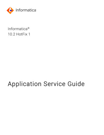
ATV11.book Page 13 Tuesday, April 16, 2002 1:10 PMSteps for Setting Up the Drive1 - Fit the drive2 - Connect the following to the drive:3 - Switch on the drive, but do not give a run command4 - Configure the following: The nominal frequency (bFr) of the motor, if it is other than 50 Hz for the E range or other than 60 Hz for theU range (only appears the first time the drive is switched on). The ACC (Acceleration) and dEC (Deceleration) parameters. The LSP (Low speed when the reference is zero) and HSP (High speed when the reference is maximum)parameters. The ItH parameter (Motor thermal protection). The preset speeds SP2-SP3-SP4. The speed reference if it is other than 0 - 5 V (0 -10V or 0 -20mA or 4 -20mA).ENGLISHFRANÇAIS The line supply, ensuring that it is:- within the voltage range of the drive- off The motor, ensuring that its coupling corresponds to the supply voltage The control via the logic inputs The speed reference via the logic or analog inputs5 - Configure the following in the drC menu:The motor parameters, only if the factory configuration of the drive is not suitable.The Altivar 11 is factory-configured for the most common operating conditions: Logic inputs:- LI1, LI2 (2 directions of operation): 2-wire control on transition, LI1 forward, LI2 reverse.- LI3, LI4: 4 preset speeds (speed 1 speed reference or LSP, speed 2 10 Hz,speed 3 25 Hz, speed 4 50 Hz). Analog input AI1: speed reference (0 5 V). Relay R1: the contact opens in the event of a fault (or drive off). DO output: analog output, image of the motor frequency.If the factory configuration is not suitable, the FUn menu can be used to modify the functions and theI/O assignments.DimensionsGa abmm mmGmmHmm Ga U05// E, U rangesU09// U range7214260 1131 1 2 x 5U09// E rangeU12// E rangeU18M/ E range7214260 1120 1 2 x 5U18M/ U range7214760 1131 1 2 x 5U18F1 U rangeU29// E, U rangesU41// E, U ranges117 142106 1131 1 4 x 5ATV 11Pabmm mmGmmHmmall ratings7260 1131 1 2 x 5142ØmmØmm13ITALIANOH bH b ATV 11H 4 2ESPAÑOLFactory configurationDEUTSCH6 - Start the drive
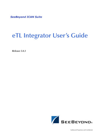
ATV11.book Page 14 Tuesday, April 16, 2002 1:10 PMMounting and Temperature Conditions 50 mm d dWhen IP20 protection is adequate, it is recommended that the protective cover stuck to thetop of the drive is removed, as shown on the next page. From -10 C to 40 C: d 50 mm: no special precautions. d 0 (drives attached together): remove the protective cover stuck to the top of the drive,as shown below (the degree of protection becomes IP20). From 40 C to 50 C: d 50 mm: remove the protective cover stuck to the top of the drive, as shown below (thedegree of protection becomes IP20). From 50 C to 60 C: d 50 mm: remove the protective cover stuck to the top of the drive, as shown below (thedegree of protection becomes IP20), and derate the drive nominal current by 2.2% forevery C above 50 C.ENGLISHFRANÇAIS 50 mmInstall the unit vertically, at 10 .Do not place it close to heating elements.Leave sufficient free space to ensure that the air required for cooling purposes can circulatefrom the bottom to the top of the unit.Free space in front of unit: 10 mm minimum.ATV 11P////// drives can be mounted on (or in) a steel or aluminium machine frame, observing the followingconditions:Maximum ambient temperature: 40 CVertical mounting at 10 The drive must be fixed at the centre of a support (frame) which is a minimum of 10 mm thick and with a squarecooling area (S) of 0.12 m2 minimum for steel and 0.09 m2 for aluminium, exposed to the open air.Support area for the drive (min 142 x 72) machined on the frame with a surface smoothness of 100 mm max anda roughness of 3.2 mm max.Mill the tapped holes lightly in order to remove any burrs.Coat the whole support surface of the drive with thermal contact grease (or equivalent). 10 mm2 tappedholesØ M5131 mmAttach the driveusing 2 M5 screws(not supplied).S 142 mmITALIANOESPAÑOLDEUTSCHMounting the drives on base platesMinimummachinedarea60 mm 72 mm9HULI\ WKH WKHUPDO VWDWH RI WKH GULYH E\ FKHFNLQJ SDUDPHWHU W G 683 PHQX WR FRQILUP WKDW WKHGULYH KDV EHHQ PRXQWHG FRUUHFWO\ 14
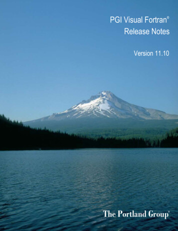
ATV11.book Page 15 Tuesday, April 16, 2002 1:10 PMPower TerminalsMaximum connection capacityTightening torque in NmAWGmm2U05///, U09///, U18M//AWG 141.50.75U18F1/, U29///, U41///AWG 1041Power supplyTo motorTo brakingmoduleTo brakingmoduleFRANÇAISPower supplyENGLISHAltivar ATV 11/To motorDEUTSCH 15VLI 4LI 3LI 2LI 1DO 5VAI 1Electrical characteristicsMin. switching capacity: 10 mA for 24 V Fault relay contact(open if there is a fault or the Max. switching capacity:drive is off) 2 A for 250 V " and 30 V on inductive load (cos j 0.4 - L/R 7 ms) 5 A for 250 V " and 30 V on resistive load (cos j 1- L/R 0)0VI/O common0VAI1Voltage or current analoginputAnalog input 0 5V or 0 10 V: impedance 40 kW, 30 V max.Analog input 0 - 20mA or 4 - 20mA: impedance 250 W (with noadditional resistor) 5VPower supply for referencepotentiometer 2.2 to 10 kW Precision: - 0 5% Max. current available: 10 mADOOutput which can beconfigured as analog orlogic outputPWM open collector analog output at 2 kHZ: voltage 30 V max., impedance 1 kW, 10 mA max.Open collector logic output: voltage 30 V max., impedance 100 kW, 50 mA max.LI1LI2LI3LI4Programmable logic inputs Power supply 15 V (max. 30 V), Impedance 5 kW State 0 if 5 V, state 1 if 11 V 15VLogic input power supply 15 V 15% protected against shorts-circuits and overloads.Max. customer current available 100 mAITALIANORCRA- Maximum connection capacity:1.5 mm2 - AWG 16- Max. tightening torque:0.5 Nm.ESPAÑOLTerminal Function0VNot usedRARCArrangement, specifications and functions of the control terminals15
ATV11.book Page 16 Tuesday, April 16, 2002 1:10 PMWiring diagram for factory settings Line supply terminals at the top, motor terminals at the bottom Connect the power terminals before the control terminals ATV11////F1/ATV11////M2/ 6LQJOH SKDVH OLQH VXSSO\ FRANÇAIS6LQJOH SKDVH OLQH VXSSO\ESPAÑOL ATV11////M3/DEUTSCHENGLISH SKDVH OLQH VXSSO\5HIHUHQFHSRWHQWLRPHWHU %UDNLQJ PRGXOH DQG UHVLVWRU RSWLRQDO(1) Fault relay contacts, for remote indication of the drive status.(2) Internal 15 V. If an external source is used ( 24 V max.), connect the 0 V of the source to the 0V terminal,and do not use the 15 V terminal on the drive.(3) Galvanometer or low level relay.Note: Fit interference suppressors to all inductive circuits near the drive or coupled to the same circuit (relays,contactors, solenoid valves, etc).ITALIANOChoice of associated components:See the Altivar 11 catalog.16
ATV11.book Page 17 Tuesday, April 16, 2002 1:10 PMFunctions of the display and the buttons Exits a menu orparameter, or aborts thedisplayed value to returnto the previous value inthe memoryESCENT Returns to the previousmenu or parameter, orincreases the displayedvaluePressing Enters a menu or aparameter, or saves thedisplayed parameter orvalue Goes to the next menu orparameter, or decreasesthe displayed valueordoes not store the choice.ENTENT# (ESCESC@1/#%)1 flash(save)ENGLISHStore, save the displayed choice :Example:ParameterValue or assignment-//FRANÇAIS 3 "7-segment"displaysThe display flashes when avalue is stored.#%)ENTDEUTSCH(Next parameter)ITALIANOESPAÑOLNormal display, with no fault present and no startup:- rdY: Drive ready- 43.0: Display of the parameter selected in the SUP menu (default selection: frequency reference).- dcb: DC injection braking in progress- nSt: Freewheel stopIf there is a default, it is shown with a flashing display.17
ATV11.book Page 18 Tuesday, April 16, 2002 1:10 PM1st level adjustment parametersDisplays the drive status:::ENGLISHFRANÇAISbFrDEUTSCHMenu: Application functionsFunMenu: MonitoringSUP-5 -5 Menus-5 Parameters in shaded boxes can be modified with the drive operating or stopped.B&R!##D%#ESPAÑOLdrC1st leveladjustmentparametersThe parameters not in shaded boxes can only be modified when the drive is stopped and locked.CodeITALIANOMenu: Motor control-5 ,30(30)T(30 30 30 !)TDescriptionAdjustment rangeFactory settingMotor frequency50 Hzor60 Hz50 (E range)or60 (U range)This parameter is only visible here the first time the drive is switched on.It can be modified at any time in the FUn menu.Acceleration ramp time0.1 s to 99.9 s3Range: 0 Hz to motor nominal frequency FrS (parameter in drC menu).Deceleration ramp time0.1 s to 99.9 s3Range: motor nominal frequency FrS (parameter in drC menu) to 0 Hz.Low speed0 Hz to HSP0LSP to 200 Hz bFrMotor frequency to 0 reference.High speedMotor frequency to max. reference.Check that this setting is appropriate for the motor and the application.Motor thermal current0 to 1.5 In (1)According to driveratingCurrent used for motor thermal protection. Set ItH to the nominal current marked on the motor ratingplate.The memory of the motor thermal state returns to zero when the drive is switched off.2nd preset speed (2)0.0 to 200 Hz103rd preset speed (2)0.0 to 200 Hz254th preset speed (2)0.0 to 200 Hz50Configuration of the analog input5U, 10U, 0A, 4A5U 5: voltage 0 - 5 volts (internal power supply) 5: voltage 0 - 10 volts (external power supply) !: current 0 - 20 mA !: current 4 - 20 mA-(1) In nominal drive current(2) The preset speeds only appear if the corresponding function has remained at the factory setting or has beenreconfigured in the FUn menu.18
ATV11.book Page 19 Tuesday, April 16, 2002 1:10 PMMotor control menu drCENTENT D;ESCValueNominal motor voltageValueMotor nominal cosine jESCENTESC/9;FRANÇAIS@H/ESCThe parameters not in shaded boxes can only be modified when the drive is stopped and locked.Parameters in shaded boxes can be modified with the drive operating or stopped.&,'5&RN#R#,)N3,3,0#/3Adjustment rangeFactory settingNominal motor voltage marked on the rating plate.100 to 500 VAcc. to ratingNominal motor frequency marked on the rating plate.40 to 200 Hz50 / 60Hz dep. onbFrFrequency loop stability0 to 100% whenstopped1 to 100% whenoperating200 to 100% whenstopped1 to 100% whenoperating20DEUTSCH3T!DescriptionValue too high: extension of response timeValue too low: speed exceeded, possible instability.Frequency loop gainValue too high: speed exceeded, instability.Value too low: extension of response timeIR compensation0 to 200%Used to optimise the torque at very low speed, or toadapt to special cases (example: for motors connectedin parallel, lower UFr).50Nominal motor current marked on the rating plate0.25 to 1.5 In (1)Acc. to ratingLimiting current0.5 to 1.5 In (1)1.5 InNominal motor slip0 to 10.0 HzAcc. to ratingESPAÑOL5N3&R3Calculate using the formula: nSL parameter bFr x (1 - Nn/Ns)Nn nominal motor speed marked on the rating plateNs motor synchronous speedSlip compensation0 to 150% (of nSL)100Used to adjust the slip compensation around the value set by the nominal motor slip nSL, or to adaptto special cases (example: for motors connected in parallel, lower SLP).Nominal motor cosine j marked on the rating plate0.50 to 1.00Acc. to rating(1) In nominal drive current19ITALIANOCodeENGLISHDrive performance can be optimised by entering the values marked on the motor rating plate
ATV11.book Page 20 Tuesday, April 16, 2002 1:10 PMApplication functions menu FUnENTFUnESCType of controltCCENTESCESCESCFCSReminder of the configurationFRANÇAISENTThe parameters not in shaded boxes can only be modified when the drive is stopped and locked.Parameters in shaded boxes can be modified with the drive operating or stopped.CodeDescriptionDEUTSCHT#TtrnType of 2-wire control(parameter can only be accessed if tCC 2C):: state 0 or 1 is taken into account for running or stopping.: a change of state (transition or edge) is necessary to initiateoperation, in order to prevent accidental restarts after a power supplyinterruption.: same as LEL, but the "forward" input always takes priority over the"reverse" input.,%,TRN0&/RR3Reverse: function inactiveto: choice of the input assigned to the reverse commandN/,) 03 ,)!ITALIANOESPAÑOLFactory settingType of control 2-wire control2C 3-wire control2-wire control: The open or closed state of the input controls running orstopping. 15 V LI1 LIxExample of wiring:LI1: forwardLIx: reverse3-wire control (pulse control): a "forward" or "reverse" pulse is sufficient tocommand starting, a "stop" pulse is sufficient to command stopping.Example of wiring: 15 V LI1 LI2 LIxLI1: stopLI2: forwardLIx: reverseTo change the assignment of tCC press the "ENT" key for 2 s. Thiscauses the following functions to return to factory setting: rrS, tCt,Atr, PS2 (LIA, LIb).!#T # #ENGLISHT##,) Preset speedsIf LIA and LIb 0: speed reference on AI1If LIA 1 and LIb 0: speed SP2If LIA 0 and LIb 1: speed SP3If LIA 1 and LIb 1: speed SP4Assignment of input LIA: function inactiveto: choice of the input assigned to LIAAssignment of input LIb: function inactiveto: choice of the input assigned to LIbSP2 is only accessible if LIA is assigned, SP3 and SP4 if LIA and LIb areassigned.N/,) ,) ,)BN/,) ,) 30 30 30 2nd preset speed, adjustable from 0.0 to 200 Hz (1)3rd preset speed, adjustable from 0.0 to 200 Hz (1)4th preset speed, adjustable
Altivar ATV 11 Maximum connection capacity Tightening torque in Nm AWG mm2 U05 , U09 , U18M AWG 14 1.5 0.75 U18F1 , U29 , U41 AWG 10 4 1 Terminal Function Electrical characteristics RC RA Fault relay contact (open if there is a fault or the drive is off) Min. switching capacity: 10 mA for 24 V Max. switching capacity: 2 A for 250 V and 30 V on inductive load (cos 0.4 - L/R 7 ms) 5 .