Transcription
Use of the Automatic Identification System (AIS) onAutonomous Weather Buoys for Maritime DomainAwareness ApplicationsP. A. LessingNational Data Buoy Center1100 Balch Blvd.Stennis Space Center, MS 39529 USACdr. B. J. TetreaultUnited States Coast Guard2100 2nd St., SWWashington, DC 20593 USAL. J. BernardUniversity of Southern Mississippi1100 Balch Blvd.Stennis Space Center, MS 39529 USAJ. N. ChaffinScience Applications International CorporationBldg. 3205Stennis Space Center, MS 39529 USAAbstract- The United States Coast Guard (USCG), as part of theDepartment of Homeland Security, is responsible for a widevariety of missions in the maritime domain. In order to supportthe accomplishment of these missions, the USCG needs to collectas much information as possible on activities occurring in themaritime domain. A large part of maritime activity relates to themovement of vessels. Therefore, detection, classification,identification and monitoring of vessels are a key component ofwhat is known as Maritime Domain Awareness (MDA).The Automatic Identification System (AIS) is a technology thatis used primarily as a tool for maritime safety, including vesselcollision avoidance and as a means for coastal nations’ VesselTraffic Services (VTSs) to get information on vessels operatingnear their coasts. AIS equipment aboard vessels continuously andautonomously transmits information about the vessel including itsidentity, position, course, and speed to enhance safety. Thesetransmissions can be received by other vessels or by land-basedstations equipped with AIS receivers. The USCG sees thecapability AIS provides, particularly for vessel tracking, as amajor contributor to MDA and VTS. To extend the capability ofUSCG land-based AIS monitoring stations further offshore, theUSCG Maritime Domain Awareness Program Integration Officesponsored the development of a near real-time, autonomousautomatic identification and telemetry system based on AIStechnology for installation on National Oceanic and AtmosphericAdministration (NOAA) weather buoys through the National DataBuoy Center (NDBC) and its technical support contractor, ScienceApplications International Corporation (SAIC).This paper discusses system design of a prototype, autonomous,buoy-based, embedded system for AIS-equipped vessel detectionusing an AIS receiver and satellite transmitter for near real-timerelay of vessel identification data. This paper also describesfollow-on enhancements to the system to further extend AIScoverage and field testing of the system. The prototype systemdevelopment began in August 2004. The prototype systemreceives AIS data from AIS-equipped vessels on a timed, periodicschedule, processes and verifies received data onboard the buoy,and relays these data from the remote weather buoy via satellite innear real-time to the NDBC Data Assembly Center (NDAC), andthen on to the USCG. The prototype system was successfully fieldtested March 2005 through June 2005 on four near-shore NDBC1-4244-0115-1/06/ 20.00 2006 IEEEbuoys located in the Strait of Juan de Fuca, near San FranciscoHarbor, near Charleston, South Carolina and near Cape Cod,Massachusetts. Field testing successfully proved the concept ofcollecting vessel identification data from an autonomous AISsystem on NDBC weather buoys. Enhancements to the systemwere developed from August 2005 to February 2006. Theseenhancements extend AIS monitoring coverage from periodic AISmonitoring to continuous monitoring and conserve system powerby insertion of NDBC weather data into the AIS data streamreturning it to NDBC using the low power satellite telemetry of theAIS system rather than the existing high power geosynchronoussatellite transmission system in use on most NDBC weather buoys.Extended field testing of the enhanced AIS system on four deepocean NDBC weather buoys began in March 2006 and willcontinue through February 2007.The installation of an AIS system on NDBC weather buoysprovides additional platforms for the use of AIS by the USCG insupport of all national maritime missions.The system alsoprovides an opportunity for NDBC to increase the temporalsampling of environmental data from buoys with the systeminstalled as a result of the increased bandwidth available using thesatellite transmitter that is part of the buoy-based AIS system andand to broadcast weather data directly to nearby vessels using theAIS. Efforts presently underway through the InternationalElectrotechnical Commission (IEC) to develop standards for realtime broadcast of environmental data over AIS marine bands tovessels using an environmental data message standard underdevelopment by the International Maritime Organization (IMO)presents NOAA/NDBC with the opportunity to provide real-timeenvironmental data directly to passing vessels in the near future.I.INTRODUCTIONThis paper describes the development and testing of a lowpower, Automatic Identification System (AIS) for use onautonomous weather buoys operated by the National Oceanicand Atmospheric Administration (NOAA), National Data BuoyCenter (NDBC). The development and integration of thissystem, which was deployed and tested on four NOAA weatherbuoys, was sponsored by the USCG, Maritime Domain
Form ApprovedOMB No. 0704-0188Report Documentation PagePublic reporting burden for the collection of information is estimated to average 1 hour per response, including the time for reviewing instructions, searching existing data sources, gathering andmaintaining the data needed, and completing and reviewing the collection of information. Send comments regarding this burden estimate or any other aspect of this collection of information,including suggestions for reducing this burden, to Washington Headquarters Services, Directorate for Information Operations and Reports, 1215 Jefferson Davis Highway, Suite 1204, ArlingtonVA 22202-4302. Respondents should be aware that notwithstanding any other provision of law, no person shall be subject to a penalty for failing to comply with a collection of information if itdoes not display a currently valid OMB control number.1. REPORT DATE2. REPORT TYPE01 SEP 2006N/A3. DATES COVERED-4. TITLE AND SUBTITLE5a. CONTRACT NUMBERUse of the Automatic Identification System (AIS) on AutonomousWeather Buoys for Maritime Domain Awareness Applications5b. GRANT NUMBER5c. PROGRAM ELEMENT NUMBER6. AUTHOR(S)5d. PROJECT NUMBER5e. TASK NUMBER5f. WORK UNIT NUMBER7. PERFORMING ORGANIZATION NAME(S) AND ADDRESS(ES)National Data Buoy Center 1100 Balch Blvd. Stennis Space Center, MS39529 USA9. SPONSORING/MONITORING AGENCY NAME(S) AND ADDRESS(ES)8. PERFORMING ORGANIZATIONREPORT NUMBER10. SPONSOR/MONITOR’S ACRONYM(S)11. SPONSOR/MONITOR’S REPORTNUMBER(S)12. DISTRIBUTION/AVAILABILITY STATEMENTApproved for public release, distribution unlimited13. SUPPLEMENTARY NOTESSee also ADM002006. Proceedings of the MTS/IEEE OCEANS 2006 Boston Conference and ExhibitionHeld in Boston, Massachusetts on September 15-21, 2006, The original document contains color images.14. ABSTRACT15. SUBJECT TERMS16. SECURITY CLASSIFICATION OF:a. REPORTb. ABSTRACTc. THIS PAGEunclassifiedunclassifiedunclassified17. LIMITATION OFABSTRACT18. NUMBEROF PAGESUU619a. NAME OFRESPONSIBLE PERSONStandard Form 298 (Rev. 8-98)Prescribed by ANSI Std Z39-18
Awareness Program Integration Office. An overview of therole of AIS in support of Maritime Domain Awareness will bediscussed. An overview of the buoy AIS system design ispresented, which includes buoy embedded system architectureand satellite data transmission system, data filtering andprocessing on the buoy, and the shore-side processing and datadistribution system. System testing and results to date are thenpresented and future long-term testing and evaluation of thesystem is discussed.II.AUTOMATIC IDENTIFICATION SYSTEM DESCRIPTIONmitigate multiple units from attempting to transmit at the sametime.Information transmitted by AIS equipment consists ofdynamic, static and voyage related information [2]. Dynamicinformation, such as vessel heading, course, speed, position,etc., is broadcast in near real-time depending on vessels’ speedand heading change. Static information (vessel identity,dimensions, etc.) is transmitted every 6 minutes as is voyagerelated data such as vessel destination, hazardous nature of itscargo, etc.B. AIS Role in Maritime Domain AwarenessMaritime Domain Awareness, or MDA, is: “The effectiveunderstanding of anything associated with the global maritimeenvironment that could affect the security, safety, economy, orenvironment of the United States. [3]” Simply stated, MDA isunderstanding what’s going on out on the water. Not surprisingly,vessel tracking – detecting, classifying, identifying and tracking ships– is critical to MDA. While MDA primarily supports maritimesecurity, its applicability goes far beyond that to support all national"1.2 The AIS should improve the safety ofmaritime missions and interests. Traditional USCG missions such asnavigation by assisting in the efficient navigation ofMaritime Safety, Search and Rescue (SAR), Vessel Trafficships, protection of the environment, and operation ofManagement and Law Enforcement are all served by MDA, and otherVessel Traffic Services (VTS), by satisfying thefederal agencies with maritime interests are supported. For example,following functional requirements:the USCG is currently working with the National Oceanic and.1 in a ship-to-ship mode for collision avoidance;Atmospheric Administration (NOAA) to use AIS in support of.2 as a means for littoral States to obtainprotection of endangered living marine resources. The primary use ofinformation about a ship and its cargo; andAIS for MDA will be the reception of AIS data transmitted from AIS.3 as a VTS tool, i.e. ship-to-shore (trafficequipped vessels for the purpose of tracking their movements. Themanagement)[1]."data collected will be disseminated to other systems in support ofmaritime safety, security, environmental protection, law enforcementAIS is very useful in identifying vessels observed by other and other missions.means (e.g., visually or by radar) and is particularly helpful indetecting vessels not able to be detected by usual means (e.g., C. USCG AIS Capabilityat night, in fog, in radar blind areas, etc.). AIS provides aThe USCG currently has extensive AIS capability throughmeans for these vessels to exchange identification, position, the Ports and Waterways Safety System (PAWSS) acquisitioncourse, speed and other data with all other nearby AIS- project and is acquiring full AIS capability throughout the U.S.maritime domain through a major acquisition calledequipped vessels and shore stations.AIS compiles shipboard sensor data (e.g., position from GPS, Nationwide AIS. Below are brief descriptions of some of theheading from gyrocompass, etc.) with ship static and voyage existing USCG AIS capability:related data into messages that are autonomously broadcast andUSCG Research and Development Center AIS Efforts. Thereceived by VHF-FM radios incorporated into the AISUSCGResearch and Development (R&D) Center in Groton,transceiver. In order to ensure that messages sent by AISCThasbeen a leader in the development of AIS technology,equipment operating in close proximity don’t interfere withstandards,and assessment of AIS capabilities. The R&Deach other, AIS equipment self-organizes its broadcasts usingCenterhasdeployed many AIS receivers around the U.S.the Self-Organizing Time Division Multiple Access (SOTDMA)coastlineandis performing detailed performance analysis ofprotocol. A minute of time is divided into 2250 slots.AIS installations on a wide variety of platforms, investigatingInformation contained in an AIS message is transmitted duringAIS network and distribution methods and a variety ofone or more of these slots. The AIS unit automatically andprototype system development efforts.autonomously determines what slots are available for its use,AIS at Vessel Traffic Services. By the end of 2004, when thebroadcasts its intentions for slot use to other units to allocatethe slots, and transmits its messages. SOTDMA sets AIS apart initial AIS carriage regulations came into force, AIS capabilityfrom other systems that rely upon receiving a shore-side was deployed at all USCG VTS areas. VTSs are USCG units‘trigger’ to make the system broadcast (i.e., a transponder) or that manage vessel traffic and provide navigation assistance toare set to a fixed broadcast schedule - both are unable to vessels somewhat analogous to air traffic control for aircraft.A. Overview of AISThe Automatic Identification System (AIS) is a system usedby vessels at sea primarily for identification of and exchange ofinformation with other vessels as an aid in collision avoidance.The International Maritime Organization (IMO) adoptedperformance standards for AIS in 1998 and set out thefollowing intended uses of AIS:
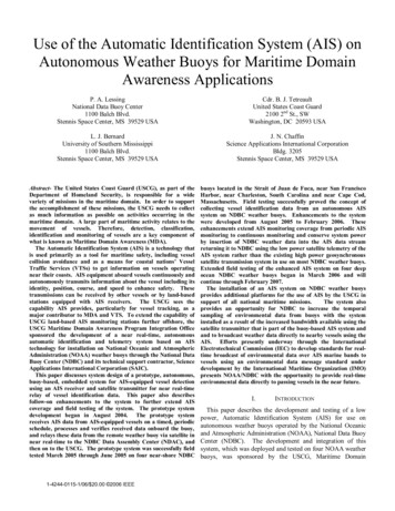
PAWSS and its AIS capability at VTSs has greatly improvedthe ability to monitor vessel traffic in the busiest U.S. ports.AIS on Offshore Platforms. AIS equipment has been placedon four existing offshore platforms used for petroleumproduction in the Gulf of Mexico. These platforms arecommunications sites operated by PETROCOM, a provider ofcellular communications services. The data is sent to theUSCG from the platforms using their existing communicationsinfrastructure. This effort has been successful in extending therange of VTS Houston/Galveston and AIS tracking in the Gulfof Mexico.Most AIS efforts in place by the USCG are land-based (AISat VTSs, R&D Center efforts, AIS at other command andcontrol centers) and thus are limited to the line of sightpropagation of the AIS VHF-FM signals, generally about 40nm offshore (coverage is very dependent on antenna height,ambient radio noise, tropospheric factors, etc.). In order todetect and identify vessels further offshore, other platformswere considered as potential for placement of AIS receivers.The existing array of buoys established and maintained byNOAA’s NDBC were an obvious choice as an offshoreplatform of opportunity. They were in ideal locations, manymore than 40nm offshore, already had complex data collectionand communications equipment integrated into them, and hadproven resiliency. The NDBC and USCG have workedtogether for many years in the design, deployment, andmaintenance of these buoys, so a partnership to leverage themas platforms for AIS was a natural choice.III.NDBC BUOY AIS SYSTEMA. System OverviewThe National Data Buoy Center operates a network of 98environmental measurement buoys that surrounds thecontinental United States coasts, Alaska south of the BeringStrait, and the Hawaiian Islands. In an effort to expand thecoverage of its AIS network farther offshore, the USCGsponsored a project to install embedded AIS receiver systemson four NDBC buoys to test the viability of receiving AIS datafurther offshore from these platforms. Four buoys weredeployed with an NDBC-developed system that integrated alow-power, commercial AIS receiver, a microcontroller-basedAIS Control Unit, and IRIDIUM satellite modem for near realtime data transmission of AIS data in early 2005 for proof-ofconcept testing. Fig. 1 is a block diagram of the AIS systemdeveloped by NDBC for the USCG. The proof-of-conceptsystem was successfully tested for a 60-day period. A modifiedsystem was then deployed on four deep ocean NDBCbuoys beginning in late spring 2006 for extended testing. Thissecond system deployment implemented design and firmwarechanges to: increase AIS receiver coverage time at the buoys to24 hours a day, 7 days a week; reduce power consumption bythe embedded buoy system; transmit environmental dataacquired by sensors on the buoy with the AIS data byIRIDIUM satellite; and interface the embedded AIS systemIRIDIUM CONSTELLATIONAISDataDoD GATEWAY HAWAIID900SBDServerIRIDIUMMODEMAISCONTROL DCENTERBuoy Embedded SystemUSCGOSCFigure 1. Block Diagram of Buoy AIS systemwith the buoy renewable power system. AIS data and NDBCenvironmental data are transmitted from these buoys byIRIDIUM satellite Short Burst Data (SBD) messages throughthe Department of Defense (DoD) secure IRIDIUM gateway inHawaii, and from there to the NDAC, where the NDBC data isextracted and the AIS data are validated and transferred to theUSCG by internet.B. Buoy Embedded System ArchitectureAIS data collection from NDBC buoys is performed by anautonomous, embedded system separate from the buoy’selectronic systems with the exception of connections to thebuoy power system and a serial connection to the NDBCenvironmental Data Collection Platform (DCP) for acquisitionof the buoy environmental data that is transmitted with AISdata packets. The AIS embedded system is shown in the lowerright of Fig 1.The embedded AIS system consists of a very low power AISreceiver, an AIS Control Unit (ACU), and an IRIDIUMsatellite data modem. The AIS receiver is a commerciallyavailable, receive-only unit capable of receiving all ITU-RM.1371-1 AIS messages on the AIS VHF data link (VDL) andoutputting these VDL messages (VDMs), that contain vesselidentification and voyage-related data, over a RS-232presentation interface to the ACU.System functions are controlled and monitored by the ACU,which is a NDBC-developed single-board computer based on alow power 68332 microprocessor. The ACU receives AIS datacontinuously from the AIS receiver, filters these data sendingback only the most recent AIS message, relative to IRIDIUMtransmission time, of each type from each unique vessel. TheACU also formats AIS data into IRIDIUM SBD packets, setsup and controls SBD data transmissions by the IRIDIUMsatellite modem, and provides power management of all AISsystem components.
The IRIDIUM satellite modem is a commercially availableIRIDIUM data modem that transmits AIS message packets tothe NDAC every ten minutes.The buoy embedded system is capable of receiving Mobileterminated, SBD messages originated by NDBC thatreconfigure the system and allow different operating scenariosof the AIS system. The system can be configured for more- orless-frequent IRIDIUM data transmissions, with the minimumtransmit duty cycle limited only by the minimum time requiredto initiate and complete an IRIDIUM SBD transmission. Datafrom the AIS receiver is continuously received and filtered bythe ACU concurrently while data is transmitted by IRIDIUMSBD.The ACU is also capable of being remotely commanded bySBD message to receive an incoming data call to the IRIDIUMmodem using IRIDIUM circuit-switched calling. This allows aremote operator to connect to the buoy system as thoughconnected by a laptop locally for extended diagnostics andconfiguration of the system. In addition, the system can passthrough commands to the NDBC DCP allowing remote reconfiguration and diagnostics of the DCP by way of the ACU.C. Land-based ArchitectureAIS data are received as SBD Packets at the NDAC from theDoD secure IRIDIUM gateway by direct Internet Protocol (IP)as they are transmitted from the buoy. These data are loggedand quality checked for any transmission errors and relayed byinternet to the USCG Research and Development Center andthe USCG Operations Systems Center (OSC), using a clientapplication developed by the USCG residing on NDBC servers.Shore-side system processing and data flow is shown in Fig 2.SBD packets containing AIS sentences are received from theDoD secure gateway at the NDAC. NDAC shore-sideprocesses strip off the DoD gateway SBD packet wrapper, andthen scan the packet for four data message types. The details ofthe SBD packet processing are shown in Fig 3.The first data message type, indicated by a “ N” header, isan NDBC environmental data message. This message type isextracted from the SBD packets and sent by file transferprotocol (ftp) to the NDBC real-time data processing serverwhere it ultimately finds its way to the National WeatherService Telecommunications Gateway (NWSTG), theAutomated Weather Information Processing System (AWIPS),and the Global Telecommunications Gateway (GTS) for furtherdissemination.The second message type, indicated by a “ R” header, is amessage generated by the embedded buoy system in responseto a Mobile-terminated command issued at the NDAC thatreconfigures the AIS system on the buoy or requestsmaintenance information from the AIS system.Thesemessages are transmitted by e-mail to NDBC operators.The third data type, indicated by a “ GPGGA” header, is thebuoy Global Positioning System (GPS) position, which isacquired once per hour by the GPS receiver embedded withinthe AIS receiver. Position is acquired only once per hour as apower saving measure and because the buoy is moored andnormally does not drift more than approximately two nauticalmiles from its moored position.The fourth data type, indicated by the header “!AIVDM,” arethe AIS VDMs. These messages contain vessel position andvoyage-related data. Each of these AIS data messages,containing 160 to 1000 bits, within a given short burst datapacket contains a checksum, which is validated by NDACshore-side processing. As each sentence is validated, it istransmitted by IP socket to a client application developed bythe USCG Research and Development Center that resides onthe NDAC AIS server. This application also keeps an externalIP socket alive to the USCG AIS servers using an embedded‘heartbeat’ function in the client to maintain a persistent socketconnection in the absence of any incoming data in order toensure minimum latency of AIS data transmitted by the NDACto the USCG. Data received by the USCG is then processed,archived and disseminated to other users and agencies.procSBDSBD FileSBD message FormatDoD IridiumGatewayUSCG AISServerNWSTGIngestServerSBD messageLog SBDDailyMessageLog NFormatRoutableMessageNWSTG FileFTP Service RMail ACUResponseACU Response MessageE-mailService!AIVDMor GPGGAProcess AISSentenceNo DataWrite toSocketSocket PortWrite toPipeFIFO Named SBDServerSetckSoDirect IP Data StructureouyyouFTP B geesssaaMesIPamtreFTP gIPSocketStreamAIS SentenceprocSBDUSCGAISUSCG AISNetworkNetworkInteraceInteraceAISSourceNDAC Network DMZ - NDBC1/NDBC2Figure 2. Shore-side Data Processing FlowFigure 3. Short Burst Data Packet ProcessingAIS Comms(source)
IV. SYSTEM TESTINGA. Test ConditionsThe AIS system was tested in two stages. A proof-ofconcept test was conducted for approximately 60 days in springof 2005. This test involved a prototype system and AISreceiver integrated into a stand-alone package which includedits own battery with sufficient capacity to operate the AISreceiver on a duty cycle of 5 minutes every 15 minutes for aperiod of approximately 60 days. The system was installed onfour near-shore NDBC buoys to allow accessibility in the eventof premature failures, and to coincide with shore-based AIScoverage for comparison of receipt of AIS messages. The buoylocations were: at the entrance to the Strait of Juan de Fucaoffshore of Neah Bay, WA; 18 nautical miles west of SanFrancisco Bay; 40 nautical miles Southeast of Charleston, SC;and 30 nautical miles east of Nantucket, MA. Fig 4 shows amap of the test buoy locations.Upon completion of this proof-of-concept testing, a secondtest of the AIS system was devised as a long-term evaluation ofthe system. The system deployed for long-term evaluation wasinstalled on four NDBC buoys farther offshore in order to testthe AIS receiver performance in the very low radio frequencynoise environment of deep ocean buoys to determine if systemrange improvements were possible in this low noiseenvironment. The buoy locations were 88 nautical miles southof Kodiak, AK, 275 nautical miles west of Coos Bay, OR, 200nautical miles east of Cape May, NJ, and 64 nautical miles eastof Virginia Beach, VA.The system deployed for this long-term evaluation includedsome firmware changes and additions based on lessons learnedfrom the proof-of-concept test. These system design changesinclude:some re-design of the AIS receiver by themanufacturer to reduce its power consumption significantlyFigure 4. Buoy Locations for Proof-of-Concept Testand to allow remote control of its embedded GPS receiver foradditional power savings; operate the AIS receivercontinuously in order that no vessels in the detection range aremissed as a result of the AIS receiver being turned off;interface the AIS system to the NDBC buoy renewable powersystem to allow operation beyond a 60-day period; and embedNDBC environmental data with the AIS data and transmit itwith the AIS data by IRIDIUM SBD packets to eliminate theneed for a GOES data transmitter normally used on NDBCbuoys as a further power savings measure. The result was asystem with better vessel monitoring capability that usedsignificantly less power than the proof-of-concept system. Thesubstantial reduction of power consumption allowed system reprogramming to transmit AIS data by SBD packets every tenminutes rather than every fifteen minutes increasing the datavolume available to the USCG.BTest ResultsTest results of the 60-day proof of concept demonstrated thatall system requirements were achieved. Typical range from thebuoys at which vessels were detected was 25 nautical miles,near the theoretical limit for marine band VHF transmissionsfor a buoy antenna height of 20 feet above the ocean surfaceand an assumed vessel antenna height of approximately 100feet above the ocean surface.Under conditions ofelectromagnetic ducting or during weather phenomenonconducive to troposphere scatter, vessels were detected as far as400 nautical miles from the buoy.System data latency was restricted by the minimum timerequired for a SBD transmission to be completed, which wasapproximately 25 to 30 seconds for packet sizes at themaximum 1960 bytes for SBD, so the minimum possible timebetween arrival of an AIS message at the buoy to its arrival atNDBC was 25 to 30 seconds. Worst case latency was as longas 5 minutes, 30 seconds which can occur when an AISsentence is received at the buoy at the beginning of the 5minute acquisition period and it is the only AIS messagereceived from that vessel during the entire acquisition period,i.e., a vessel that makes a grazing pass at the limit of the buoyAIS radio range. Observed latencies were nearly always undertwo minutes with typical latencies on the order of 40 seconds.Typical internet latencies from the DoD gateway SBD server tothe NDAC server, or from NDAC server to the USCG AISserver were under one second for each transmission leg.IRIDIUM SBD transmission reliability during the test periodexceeded 98 percent reception of the total SBD messageattempts from all buoys. The IRIDIUM gateway downlinkcommand and control signal operates in the Ka-band of thespectrum. This frequency band is subject to rain fade and thusthere is a possibility of missed transmissions due to theoccurrence of rain fade, an event which can occur frequently inHawaii, the location of the DoD gateway. Given the frequencyof potential rain fade events at this location, 98 percentsuccessful transmission of all SBD messages attemptedexceeded expectations.
The embedded buoy system power consumption for theproof-of-concept system was determined as 2.12 Amperehours/day for an AIS receiver duty cycle of 5 minutes on every15 minutes.At the time of publication of this paper, two of the foursystems for long-term testing were deployed. The locations ofthe two deployed systems locations were 88 nautical milessouth of Kodiak, AK and 64 nautical miles east of VirginiaBeach, VA.Typical maximum ranges for detected vessels at these buoyswere 40 nautical miles from the buoys. Both buoys are 6-meternomad buoys with AIS VHF antenna heights at 20 feet abovethe ocean surface.Preliminary indications show animprovement of detection range on the order of 60% for thesame buoy antenna heights used in proof-of-concept testing.This is believed to be a result primarily of the much lower radiofrequency noise environment of the deep ocean buoys, whichare much farther from land-based sources of radio interference.There was one instance of apparent electromagnetic ductingduring the test period where barge traffic was detected fromMemphis, TN, at the Virginia Beach, VA buoy, which is morethan 700 nautical miles from the buoy, although this was anuncommon occurrence.System data latency was similar to that seen in the proof-ofconcept tests, however in high traffic areas, more than one SBDmessage is required to send back all the data collected. This isa result not only of increased vessel traffic, but of the AISreceiver continuously monitoring the AIS frequencies, ratherthan only 5 minutes every 15 minutes. The increasedmonitoring time results in collection of data that may have beenmissed with the proof-of-concept system that operated withreduced AIS receiver on time. Each additional SBD packetadds 25 to 30 seconds to data latency.IRIDIUM SBD transmission reliability to date has exceeded98% on the station south of Kodiak, AK and 99% on the stationeast of Virginia Beach, VA.The buoy embedded system power consumption wasmeasured pre-deployment and found to be 2.95 Amperehours/day for an AIS receiver on continuously, with SBDtransmissions every 10 minutes rather than every 15 minutes aswith the proof-of-concept system, a substantial decrease insystem power consumption.V. CONCLUSIONThe development and testing of a buoy-based AISmonitoring system, as described, demonstrated the feasibility ofextended offshore monitoring of vessel traffic on the AISfrequencies from buoys. This system can extend coverage ofthe present capability of shore-based AIS monitoring stations,which are subject to significantly more radio frequencyinterference from land-based transmitters than is AIS receivingequipment on offshore buoys. System proof-of-concept wassuccessfully demonstrated with a limited power, limitedmonitoring time system. Extended te
National Data Buoy Center 1100 Balch Blvd. Stennis Space Center, MS 39529 USA L. J. Bernard University of Southern Mississippi 1100 Balch Blvd. Stennis Space Center, MS 39529 USA Cdr. B. J. Tetreault United States Coast Guard 2100 2nd St., SW Washington, DC 20593 USA