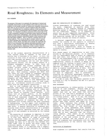
Transcription
DESIGN OF MACHINE ELEMENTSNivish George
Poor Design?Department of Mechanical ign-decisions-fails/
Machine Design Definition– Machine Design is defined as the use of scientificprinciples, technical information and imaginationin the description of a machine or a mechanicalsystem to perform specific functions withmaximum economy and efficiency– Design is an innovative and highly iterativeprocessDepartment of Mechanical Engineering3
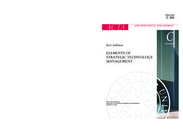
The Design Process MarketsurveyDepartment of Mechanical Engineering4
Contd Ref: m/Tata/Tata NanoProduct SpecificationDepartment of Mechanical Engineering5
Contd Selection of MechanismDepartment of Mechanical Engineering6
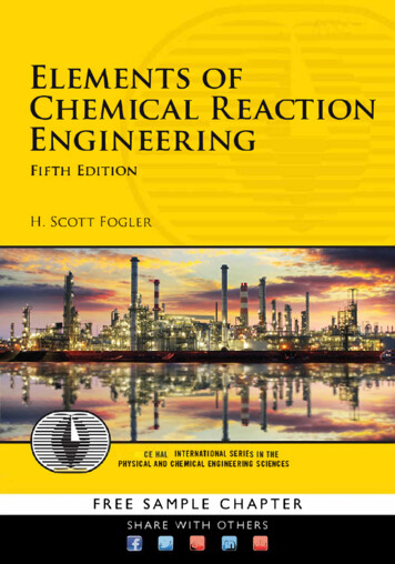
Contd Layout of configuration and selection ofjoining methodsRef. Automobile Engineering, Vol-1, Dr. Kirpal SInghDepartment of Mechanical Engineering7
Contd Design ofIndividualComponentsDepartment of Mechanical Engineering8
Contd PrepareAssembly anddetail drawing Modify drawingsafter om/2013/10/08/oldhamscoupling/Department of Mechanical Engineering9
Course ContentsMod. 1Mod. 4Mod. 2Mod. 3Mod. 5Mod. 6Department of Mechanical Engineering10
Basic RequirementStrengthMin. eMachineElementsMin. Dim.AndweightReliabilityConformanceto StandardsManufacturabilitySafetyDepartment of Mechanical Engineering11
TRADITIONAL DESIGN METHODS Design by craft ock cart.htmlRef:http://directboats.com/rowboats.html Design by drawingDepartment of Mechanical Engineering12
PROCEDURE IN DMESpecify functions Bearing Spring Screw fasteningForcedeterminationSelection ofMaterial Free body diagram Availability Man. Considerations PropertiesWORKINGDRAWINGFailure Criterion Elastic deflection General yielding FractureGeometry &DimensionsDesignModifications Operating conditions Basis of failurecriterion Assembly &manufacturingconsiderationsDepartment of Mechanical Engineering13
DESIGN SYNTHESISDesign Synthesis is defined as the process ofcreating or selecting configurations, materials,shapes and dimensions for a onDepartment of Mechanical Engineering14
AESTHETIC CONSIDERATIONSDepartment of Mechanical Engineering15
ERGONOMIC CONSIDERATIONSErgonomics is defined as the relationship between manand machine and the application of anatomical,physiological and psychological principles to solve theproblems arising from man-machine relationship Design of driver’s seatLayout of instrument dials and display panelsDesign of hand levers and hand wheelsEnergy expenditure in hand and foot operationsLighting, noise and climatic conditions in machineenvironmentDepartment of Mechanical Engineering16
Contd .Display instrumentsControl instrumentsQuantitative measurementEasily accessible and logically positionedState of affairsConform to the anatomy of human partsPredetermined settingsProper colourDepartment of Mechanical Engineering17
Overview Need of . Definition ?Requirement Procedure Tradition Synthesis Design considerationsDepartment of Mechanical Engineering18
StandardizationThe obligatory norms, to which various characteristics of a productshould conform. Standards: Set of specifications for parts, materials or processes Codes: Set of specifications for analysis, design, testingStandardsCompanyStandardsEg: ServiceStandardsNationalStandardsEg: IS, DINDepartment of Mechanical EngineeringInternationalStandardsEg:ISO19
StandardizationThe characteristics include materials, dimensions and shapeof the component, method of testing and method ofmarking, packing and storing of the product. Standards for materials, their chemical compositions,Mechanical properties and Heat Treatment FG 150, FG 200, FG 220- (IS 210): Strength 55Cr3- (IS 570 Part 4): Chemical composition Standards for shapes and dimensions of commonly usedmachine elements Dimension and cross section of V belts (IS 2494)Department of Mechanical Engineering20
Standardization Standards for fits, tolerances and surface finish ofcomponent Fit IS 2709 (Guide for selection of fits) Tolerances IS 919 (Recommendations for limitsand fits for engineering) Surface texture IS 10719 Standards for testing of products Testing of pressure vessels IS 2825 Standards for engineering drawing of components SP46 by BIS for engineering drawingsDepartment of Mechanical Engineering21
Standardization: Advantages Reduction in types and dimensions of identicalcomponents Reduced manufacturing facilities required forindividual organisation Easy replacement and availability Reduced designer tasks Improved quality and reliabilityDepartment of Mechanical Engineering22
Selection of Preferred sizes Size of the machine element with 01.03Department of Mechanical EngineeringReducingIncreasing23
Preferred NumbersDepartment of Mechanical Engineering24
Elasticity Elasticity is defined as the ability of the material to regain its original shapeand size after the deformation, when the external forces are removed Steel is perfectly elastic within a certain limit Amount of deformation a metal undergoes is small Atoms are displaced from their original positions but they don’t take upnew positionsDepartment of Mechanical Engineering25
Plasticity Plasticity is defined as the ability of the material to retain thedeformation produced under the load on permanent basis External force deforms the metal to such an extent it cannot fullyrecover Some metals take up extensive deformations without fracture Atoms are permanently displaced to take up new positionsDepartment of Mechanical Engineering26
Types of MaterialsCast ironPlain carbonsteelsPlasticsRubberAlloy SteelsCast SteelCeramicsDepartment of Mechanical Engineering27
Factors for stMechanicalPropertiesDepartment of Mechanical Engineering28
Weighted Point Method1234 Study of application and preparing a list ofdesirable properties Desirable properties are assigned values Go-no-go parameters Discriminating parameters Weightage is providedDepartment of Mechanical Engineering29
Weighted Point Method: EgS.PropertyNo.Low alloy 1Ultimate tensilestrength (N/mm2)85085012009502Hardenability Index608030100 Points for ultimate tensile strength Sum 850 850 1200 950 3850 Rating strength 850/3850 0.22 Weightage index 0.22*5 1.1 Points for hardenability Sum 60 80 30 100 270 Rating hardenability index 60/270 0.222 Weightage index 0.22*3 0.666Department of Mechanical Engineering30
Stress ConcentrationP t AMb y b IMtr JThe localization of high stresses due to theirregularities present in the component and abruptchanges of cross-sectionDepartment of Mechanical Engineering31
Causes of stress concentration Variation in properties Load applicationDepartment of Mechanical Engineering32
Contd Abrupt changes in dimensionDepartment of Mechanical Engineering33
Contd Discontinuities in the component Machining ScratchesDepartment of Mechanical Engineering34
Stress Concentration Factor (Kt)𝜎𝑚𝑎𝑥 𝜏𝑚𝑎𝑥𝐾𝑡 odsDepartment of Mechanical Engineering35
Stress Concentration factors𝑃𝜎𝑜 𝑤 𝑑 𝑡𝑃𝜎𝑜 𝑑𝑡Department of Mechanical Engineering36
Stress Concentration factors𝑃𝜎𝑜 𝜋𝑑24𝑀𝑏 𝑦𝜎𝑜 𝐼Department of Mechanical Engineering37
Stress Concentration factors Ductile materials under static load Ductile materials under fluctuating load Brittle materialsDepartment of Mechanical Engineering38
Reduction of Stress Concentration Additional Notches and Holes in Tension Member Use of multiple notches Drilling additional holes Removal of undesiredmaterialDepartment of Mechanical Engineering39
Reduction of Stress Concentration Fillet radius, undercutting and notch for memberin bending Fillet Undercut Notch Drilling additional holes for shaft Fillet SymmetricalholesDepartment of Mechanical Engineering40
Reduction of Stress Concentration Reduction of stress concentration in threadedmembers Undercut Reduction inShank diameterDepartment of Mechanical Engineering41
Simulation results Abrupt changes in section yield 804.42MPaDepartment of Mechanical Engineering42
Problem?A flat plate subjected to a tensile force of 5 kN isshown in Figure. The plate material is of grey castiron FG 200 and the factor of safety is 2.5.Determine the thickness of the plate.Objective: Find t,Given data (Check for consistency in units)P 5kNSut 200 N/mm2(fs) 2.5D 45mm,d 30mm, w 15mm, r 5mm𝜎𝑚𝑎𝑥𝑆𝑢𝑡 𝑓𝑠𝐷𝑑𝑟𝑑Department of Mechanical Engineering43
Tolerances Permissible variation in dimensions of thecomponent Types: Unilateral and bilateralRef. Design of Machine elements, Third edition, V B BhandariDepartment of Mechanical Engineering44
Fits When twoparts are tobeassembled,therelationshipresultingbetweentheir sizesbeforeassemblyVery looseLooseTightDepartment of Mechanical Engineering45
Classification- FitsDepartment of Mechanical Engineering46
Classification- FitsClearancefitTransitionfitInterferencefitRef. Design of Machine elements, Third edition, V B BhandariDepartment of Mechanical Engineering47
Classification- Fits Hole size: Constant Shaft size: Varying Hole size: Varying Shaft size: ConstantDepartment of Mechanical Engineering48
Classification- Hole basis tolerance system (H)ClearancefitTransitionfitInterferencefitRef. Design of Machine elements, Third edition, V B BhandariDepartment of Mechanical Engineering49
Classification- Shaft basis tolerance system (h)ClearancefitTransitionfitInterferencefitRef. Design of Machine elements, Third edition, V B BhandariDepartment of Mechanical Engineering50
BIS SYSTEM: ToleranceH7g6FundamentaldeviationMagnitude oftoleranceRef. Design of Machine elements, Third edition, V B BhandariDepartment of Mechanical Engineering51
BIS SYSTEM: ToleranceRef. Design of Machine elements, Third edition, V B BhandariDepartment of Mechanical Engineering52
TOLERANCE GRADINGGrade of Tolerance: Group of tolerances, whichare considered to have the same level ofaccuracy for all basic sizes.Department of Mechanical Engineering53
BIS SYSTEM:FITSBasic size common to both componentsfollowed by symbols for tolerance of eachcomponent50 H 9 / d 950 H 9 d 9H950d9Selection of fit is based on theclearance required for thedesired applicationsDepartment of Mechanical Engineering54
–Machine Design is defined as the use of scientific principles, technical information and imagination in the description of a machine or a mechanical system to