Transcription
Calix ODC-100 Installation GuideJanuary 2016#220-00221, Rev.16
ContentsAbout This Guide. 9Chapter 1: ODC-100 Product Overview . 11Cabinet Description . 12Cabinet Features . 13Cabinet Options . 14Cabinet Dimensions and Weights . 16Cabinet Views . 17Chapter 2: Installation Considerations . 19Installation Process Overview . 20Installation Guidelines . 21Space Requirements . 23General Safety Recommendations . 24Installation Kit . 25User-Supplied Items . 26Cabling Requirements . 27Chapter 3: Preparing the Installation Site . 29Installing a Ground Circuit. 30Constructing a Concrete Pad . 33Pad Construction Guidelines . 33Proprietary Information: Not for use or disclosure except by written agreement with Calix. Calix. All Rights Reserved.
4Assembling the Cast-In-Place Template . 36Preparing the Site . 37Casting the Pad . 38Installing a Pre-Cast Concrete Pad . 39Pre-Cast Pad Requirements . 39Preparing the Site . 42Installing a Pre-Cast Pad . 43Installing a Pole-Mount Kit: Remote Power. 44Pole Mounting Guidelines . 44Preparing the Site . 47Installing the Pole-Mount Kit . 47Installing a Pole-Mount Kit: Local Power with 60 Ah Battery Base(s) . 52Pole Mounting Guidelines . 52Preparing the Site . 57Installing the Pole-Mount Kit . 58Installing a Wall-Mount Kit: Local Power with 60 Ah Battery Base(s) . 64Wall/H-Frame Mounting Guidelines . 64Preparing the Site . 68Installing the Wall-Mount Kit . 69Installing a Foundation Vault. 73Foundation Vault Requirements . 73Preparing the Site . 75Installing the Foundation Vault . 76Chapter 4: Installing the Cabinet . 77Unpacking the Cabinet . 78Operating Cabinet Doors . 79Preparing the Cabinet for Installation . 81Installing the Cabinet on a Concrete Pad . 82Installing the Cabinet on a Wall or H-Frame. 85Installing the Cabinet on a Pole: Remote Power . 87Installing the Cabinet on a Pole: Local Power with 60 Ah Battery Base(s) . 90Installing the Cabinet on a Foundation Vault . 92Proprietary Information: Not for use or disclosure except by written agreement with Calix. Calix. All Rights Reserved.
5Removing the Lifting Details . 94Chapter 5: Installing Power . 95Installing the Cabinet Ground Connection . 96Installing AC Power (220-240 VAC) . 99Installing Remote Power . 101Installing Outside Plant Metallic Cable (Power Pairs) . 101Checking Line Validity for Remote Power . 102Splicing Power Pairs to the Protection Interface . 103Chapter 6: Installing and Splicing Outside Plant Cables . 105Bonding Cable Sheaths . 106Installing Fiber Cable . 107Installing Outside Plant Fiber Cable . 107Splicing Fibers . 109Connecting Fibers to the Equipment . 110(Optional) Interlinking Collocated Service Units . 112Installing Metallic Cables . 115Installing Outside Plant Metallic Cables . 115Splicing Metallic Cables . 116Installing 5-Pin Protection Modules . 117Sealing Cable Entry Locations . 118Chapter 7: Turning Up the Cabinet Power System . 119Turning Up the Power System (Local Power) . 120Checking the Ground Connection . 120Checking the AC Power Supply Voltage . 121Installing the Rectifier Modules . 122Installing Batteries. 123Turning Up and Testing the DC Power System . 131Turning Up the Power System (Remote Power) . 134Checking the Ground Connection . 134Checking the Line Power Supply Voltage . 135Installing the Converter Shelf Fan Tray. 136Proprietary Information: Not for use or disclosure except by written agreement with Calix. Calix. All Rights Reserved.
6Installing Converter Modules . 137Turning Up and Testing the DC Power System . 139Chapter 8: Installing Equipment and Adding Capacity . 141Installing an E7-2 Shelf . 142Installing a B6-001 Shelf . 146Installing an E5-100 Service Unit . 149Installing a Rear Wall Mounted Service Unit . 152Installing a Protection Mounting Frame . 154Installing a Protection Block . 157Installing a Cross-Connect Panel . 159Installing a Battery Compartment Riser . 161Installing a Battery Heater . 162Installing a Seismic Protection Kit . 165Installing a Generator Connector . 168Installing an Ethernet-over-Copper Trunking Unit . 171Installing Fiber Management Options . 175Chapter 9: Cabinet Maintenance . 177Routine Maintenance . 178Checking Cabinet Surfaces . 178Checking Electrical Components . 178Checking Cable Connections. 179Checking the Heat Exchanger . 180Battery Maintenance . 180Replacing Parts and Equipment. 183Removing a Cabinet Door. 183Installing a Cabinet Door. 184Replacing the Cabinet Roof . 186Replacing AC Breakers. 186Replacing Fuses and DC Breakers . 187Proprietary Information: Not for use or disclosure except by written agreement with Calix. Calix. All Rights Reserved.
7Replacing Rectifier Modules . 189Replacing Converter Modules. 191Replacing Batteries . 191Replacing a Battery Heater . 192Chapter 10: Reference Information . 195Specifications . 196Copper Access Cable Connections . 198Environmental Alarm Mapping to E7-2 . 200Environmental Alarm Mapping to B6-001 . 201Environmental Alarm Mapping to E5 . 202Eltek FPS Rectifier Alarm Matrix . 204Eltek FPS Rectifier Controller Settings. 205Supported Batteries . 208Wiring Diagrams . 209Proprietary Information: Not for use or disclosure except by written agreement with Calix. Calix. All Rights Reserved.
8Proprietary Information: Not for use or disclosure except by written agreement with Calix. Calix. All Rights Reserved.
9About This GuideThis document provides a general installation practice for the Calix ODC-200 outdoorcabinet. This document also provides a general description of the cabinet and its subsystems,guidance for planning, site preparation, power installation, splicing to the outside plant,component installation and expansion, and cabinet maintenance.Intended AudiencesThis document is intended for use by network planning engineers, outside plant engineers,field support personnel, and craft personnel responsible for cabinet installation, splicing,equipment installation, and maintenance.Federal Communications Commission (FCC) StatementThis equipment has been tested and found to comply with the limits for a Class A digitaldevice, pursuant to Part 15 of the FCC rules. These limits are designed to provide reasonableprotection against harmful interference when the equipment is operated in a commercialenvironment. This equipment generates, uses, and can radiate radio frequency energy, and, ifnot installed and used in accordance with the instruction manual, may cause interference toradio communications. Operation of this equipment in a residential area may cause harmfulinterference; the user will be required to correct the interference at his expense.Proprietary Information: Not for use or disclosure except by written agreement with Calix. Calix. All Rights Reserved.
10Safety NoticesThis document uses the following safety notice conventions.DANGER! Danger indicates the presence of a hazard that will cause severepersonal injury or death if not avoided.WARNING! Warning indicates the presence of a hazard that can cause severepersonal injury if not avoided.CAUTION! Caution indicates the presence of a hazard that can cause minor tomoderate personal injury if not avoided.ALERT! Alert indicates the presence of a hazard that can cause damage toequipment or software, loss of data, or service interruption if not avoided.DANGER! CLASS 1 LASER PRODUCT. INVISIBLE LASER RADIATION MAYBE PRESENT. Fiber optic radiation can cause severe eye damage or blindness.Do not look into the open end of an optical fiber.Proprietary Information: Not for use or disclosure except by written agreement with Calix. Calix. All Rights Reserved.
Chapter 1ODC-100 Product OverviewThis chapter provides a general description of the Calix ODC-100 outdoor cabinet, includingits standard features and options.Topics CoveredThis chapter covers the following topics: A description of the ODC-100 cabinet.A list of standard cabinet features.A list of cabinet options.Listed cabinet dimensions and weights.Views of the cabinet compartments.Proprietary Information: Not for use or disclosure except by written agreement with Calix. Calix. All Rights Reserved.
12Cabinet DescriptionThe Calix ODC-100 cabinet is an environmentally-controlled outdoor enclosure designed tohouse and protect network electronics equipment, including the Calix E7-2 Ethernet ServiceAccess Platform (ESAP), B6-001 Ethernet Service Access Node (ESAN), and the E5-100ESAN product family. Use the ODC-100 to provide services from a remote node locationdeep inside the customer serving area, beyond the direct reach of the carrier Central Office.The ODC-100 cabinet has a single compartment that houses electronics equipment togetherwith fiber and copper plant terminations, enabling deployment of multiple applications fromone node. The electronics area is equipped with a vertically-oriented 19-inch equipment rackthat provides 4 RU of mounting space. The ODC-100 houses up to three Calix E7-2 or B6001 shelves, or up to two E5-100 service units.The ODC-100 supports local or remote power configurations. The local power configurationincludes an additional base compartment to support battery reserve power.The modular design of the ODC-100 enables incremental expansion of system capacity,lowering initial deployment costs while maintaining the capacity for future growth. Modularcomponents designed for expansion include the compact Calix service units, copper lineprotection, fiber management capacity, DC power modules, and cooling elements.Proprietary Information: Not for use or disclosure except by written agreement with Calix. Calix. All Rights Reserved.
13Cabinet FeaturesStandard features of the ODC-100 cabinet include:Enclosure Design Environmentally sealed design protects from dust and water intrusionGR-487 compliant and UL-67 specEnvironmentally rated from -40C to 46C (per GR-487)Environmental and intrusion alarm systemsEquipment Support 19-inch equipment rack provides 4 RU of mounting spaceMechanical support for fiber and copper plant terminationsModular, scalable copper line protection (50-pair block increments, 300 pairs maximum)Door-mounted 300W heat exchangerPower (Local)Standard features for the local power configuration include: 240 VAC load center (ETL-listed); 30 Amp capacityAC main/service disconnect breakerAC surge suppressorDuplex convenience outlet (GFCI protected)Eltek Flatpack S (FPS) compact DC rectifier shelfFuse-protected DC supply to equipmentLow voltage DC disconnect (-42 VDC)Battery backup in separate vented compartmentUp to 62 Ah battery reserve capacity (breaker-protected); up to 124 Ah capacity withsecond-string riser optionPower (Remote)Standard features for the remote power configuration include: 190 VDC line power supplied over twisted pairs Line protection for up to 50 power pairs; MS2 interface connectorTyco 190 VDC to -48 VDC converter shelf (CPS2500D)Fuse-protected DC supply to equipmentFan tray for cooling converter shelfProprietary Information: Not for use or disclosure except by written agreement with Calix. Calix. All Rights Reserved.
14Cabinet OptionsCommon options for the ODC-100 cabinet include:Enclosure Mounting Concrete pad mounting: pre-cast or site-cast pad (using Calix pad template)Pole, wall, or frame mounting (using Calix mounting kits)Foundation vault mounting (third-party supplied)Adjunct enclosure mounting (ex: 3M 4220 cross-box enclosures)Calix Platform Equipment Calix E7-2: Up to 3 shelves; GPON or Active Ethernet fiber access; VDSL2 with POTS(combo or overlay) copper access; 10GE transport & aggregationCalix B6-001: Up to 3 shelves; GPON or Active Ethernet fiber access; ADSL2 orVDSL2 with POTS (combo or overlay) copper access; 10GE transportCalix E5-100: Up to 2 service units; ADSL2 or VDSL2 with POTS (combo or overlay)copper accessCalix E5-400: Up to 3 transport & aggregation unitsCopper Protection & Trunking, Splicing & Distribution, Cable Management Copper line protection for up to 292 lines; MS2 interface connectors Cross-connect panel with MS2 interface connectors; 2:1 subscriber-to-equipment linecounts: 300 pair (200:100) or 150 pair (100:50) optionsEthernet over Copper (EoCu) trunking kit for copper transport: Integrated Actelis ML600 or Positron/Aktino AK525 trunking unit for up to 8-pairbonded trunks Integrated 25-pair trunk line protection module; RJ-25/MS2 interface connectorsFiber splice trays (up to 3), each holds up to 12 fiber splices (fusion or heat shrink)High density fiber management options (48- and 96-position fiber distribution panels,1:32 PON splitters, management accessories)Clearfield xPAK low count fiber distribution with LGX mountingPower Local power support (commercial AC power supply); additional options include: 220/240 VAC input Generator connector (Hubbell); 30A NEMA twist lock with breakerProprietary Information: Not for use or disclosure except by written agreement with Calix. Calix. All Rights Reserved.
15 Remote power support ( 190 VDC line power supply): N 1 converter module redundancy ( 190 to -48 VDC modules) Optional 665W remote power buffer (holdover) capacitorBattery Support (local power configurations) Northstar or Enersys (OEM) battery string and installation kit (OEM)Battery heater kitZone 4 seismic protection kitBattery compartment riser (supports second 60 Ah or 62 Ah battery string)Proprietary Information: Not for use or disclosure except by written agreement with Calix. Calix. All Rights Reserved.
16Cabinet Dimensions and WeightsThe external dimensions of the ODC-100 cabinet are shown below.DimensionMeasurement (SAE)Measurement (Metric)Height:Remote PowerLocal Power37 inches48 inches94 cm122 cmWidth18 inches (remote power)19.7 inches (60 Ah battery base)46 cm50 cmDepth24 inches61 cmNote: Based on the dimensions, the cabinet can withstand 79.5 lbs of wind force.The approximate weight of the ODC-100 cabinet is shown below.ConfigurationWeight (SAE)Weight (Metric)Remote power, 96 copper lines135 lb61 kgLocal power (60 Ah batteries), 96 copper lines222 lb101 kgProprietary Information: Not for use or disclosure except by written agreement with Calix. Calix. All Rights Reserved.
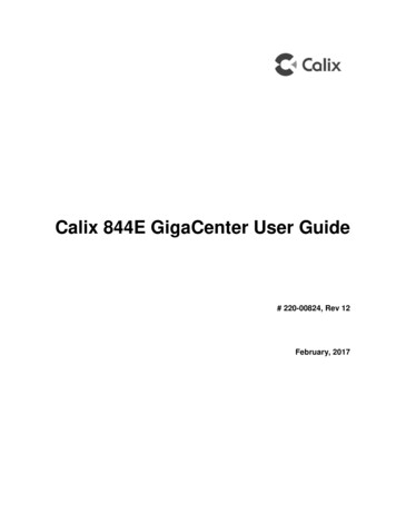
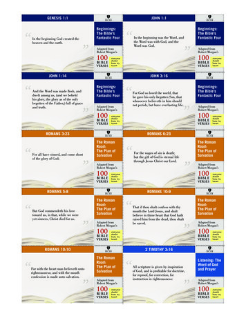
17Cabinet ViewsViews of the ODC-100 cabinet follow.Front CompartmentThe front compartment provides access to the electronics equipment, cabinet power system,and fiber management or copper line protection. The cabinet power system consists of anAC load center and DC rectifier shelf (local power configurations), or a 190/-48 VDCconverter shelf (remote power configurations). The Calix equipment typically includes up totwo or three Calix service units. For fiber access, the fiber management accessories may varygreatly according to the ordered options. For copper access, the line protection may includeup to six 50-pair protection blocks.ODC-100 Front(local power)ODC-100 Front(remote power)Side CompartmentThe side compartment provides access to the cable entry and splice locations and the mainground bar. The side compartment also houses an optional cross-connect panel for copperaccess systems. For remote power configurations, the power protection block (for the linepower pairs) is accessible from the side compartment.Proprietary Information: Not for use or disclosure except by written agreement with Calix. Calix. All Rights Reserved.
18ODC-100 SideODC-100 Side(cross-connect)Battery Compartment (Local Power)Cabinets configured for local power include a battery base compartment for housing onestring of front-access VRLA batteries.Battery compartment interior dimensions (for batteries): 10.3 (H) x 18.6 (W) x 11.5 (D)inches (26.2 x 47.2 x 29.2 cm)Note: Batteries fit compactly in the 60 Ah base. Use only approved batteries to meet seismiccompliance and follow the installation instructions to ensure a proper fit in the compartment.Proprietary Information: Not for use or disclosure except by written agreement with Calix. Calix. All Rights Reserved.
Chapter 2Installation ConsiderationsThis chapter provides general considerations for cabinet installation. Review this informationbefore starting the cabinet installation process.Topics CoveredThis chapter covers the following topics: Installation process overviewInstallation guidelinesSpace requirementsGeneral safety recommendationsInstallation kit contentsUser-supplied itemsCabling requirementsProprietary Information: Not for use or disclosure except by written agreement with Calix. Calix. All Rights Reserved.
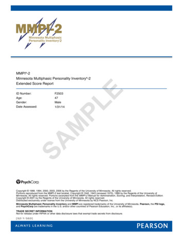
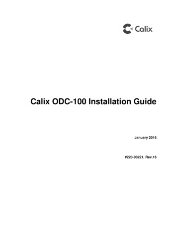
20Installation Process OverviewThe cabinet installation process involves the following high-level steps:Proprietary Information: Not for use or disclosure except by written agreement with Calix. Calix. All Rights Reserved.
21Installation GuidelinesReview the following guidelines before starting installation activities.General GuidelinesFollow these general guidelines and practices: Read this document completely before starting any installation activities.Only qualified personnel should perform the procedures described in this document.Follow standard safety precautions when performing installation and maintenance tasks.Always wear standard safety gear when performing installation and maintenance tasks(hard hats/safety headgear, eye protection, insulated gloves).For safety, keep bystanders and other unauthorized personnel away from workoperations at all times.Do not perform installation activities when the threat of lightning is present.Seal all cable entry locations immediately after the cabinet is installed to prevent groundmoisture from condensing inside the cabinet and damaging equipment.Site SelectionThe location of a cabinet installation site should be carefully planned in advance. Considerthe following factors when selecting an installation site:1. Functional requirements: Suitable terrain. Whenever possible, the cabinet should be located in an area with afirm flat soil surface that does not require extensive earth work. The location shouldnot be constantly damp or prone to flooding. Check soil maps of potential sites forsubsurface conditions. Grounding properties. The earth at the cabinet location should have a low groundimpedance to provide an effective grounding system for lightning protection andsafety. Perform ground testing to determine the grounding requirements. Safety. Whenever possible, the cabinet should be located on vacant property awayfrom motor traffic to reduce injury risks to maintenance personnel or damage toequipment. On streets and highways, avoid locations near busy intersections orcurves in the road. Erecting guard rails or concrete pillars can provide additionalsafety barriers against motor traffic. Solar exposure. Whenever possible in hot or warm climates, avoid locations withheavy exposure to direct afternoon sun, so as to maximize the life of electronicsequipment in the cabinet. High outdoor temperatures and heavy solar exposure raisetemperatures inside cabinets, a condition that can reduce the life span of equipment.Conversely, wind exposure improves thermal conditions in a cabinet, so locationsthat do not block wind are desirable.Proprietary Information: Not for use or disclosure except by written agreement with Calix. Calix. All Rights Reserved.
222. Accessibility requirements: Easement size. Select a location with an easement that provides enough space towalk around the perimeter of the cabinet with its doors open. Right-of-Way. Secure a permanent location on private property, whenever possible.Obtain a firm right-of-way agreement that includes right of access. Avoid locations inpublic rights-of-way. Electrical access. Locally-powered cabinets must have access to commercial ACpower. Verify the availability of AC service at potential cabinet locations. Parking. Whenever possible, the cabinet should be located in an area that providessufficient parking space for installation and maintenance vehicles.Proprietary Information: Not for use or disclosure except by written agreement with Calix. Calix. All Rights Reserved.
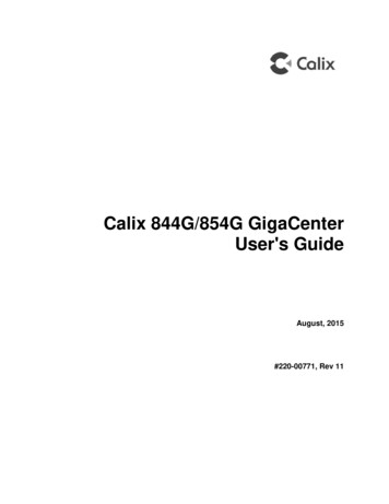
23Space RequirementsThe illustration below shows the cabinet clearance and space requirements.The minimum clearance area around the cabinet site must be free of permanent impedimentsto allow full swing of the cabinet doors. This area must be kept clear of obstructions at alltimes to provide adequate access for all installation and maintenance activities.Proprietary Information: Not for use or disclosure except by written agreement with Calix. Calix. All Rights Reserved.
24General Safety RecommendationsWARNING! Only trained, qualified technical personnel should perform theprocedures described in this document. These procedures involve potentiallyhazardous activities, including handling of heavy equipment and exposure to highelectrical energy, which could cause injury to untrained personnel.DANGER! Risk of high power current surge and electric shock. Read andunderstand all power procedures before performing tasks. Take necessaryprecautions and use appropriate insulated tools when working with power. Thisequipment must be installed, operated, and serviced by qualified technicalpersonnel only.WARNING! The cabinet and its components are heavy. Handle with care to avoidpersonal injury or damage to the equipment.DANGER! CLASS 1 LASER PRODUCT. INVISIBLE LASER RADIATION MAYBE PRESENT. Fiber optic radiation can cause severe eye damage or blindness.Do not look into the open end of an optical fiber.CAUTION! Batteries contain a stored charge. Handle
This document provides a general installation practice for the Calix ODC-200 outdoor cabinet. This document also provides a general description of the cabinet and its subsystems, guidance for planning, site preparation, power installation, splicing to the outside plant, component installation and expansion, and cabinet maintenance.