Transcription
Clearfield ODC-200 InstallationGuideManual 019564Rev AFebruary 2018
ContentsAbout This Guide. 7Chapter 1 ODC-200 Product Overview . 8Cabinet Description . 9Cabinet Features . 10Cabinet Options . 11ODC-200 Battery Riser Description . 13ODC-200 Expansion Module Description . 14Cabinet and Expansion Module Views . 16Cabinet and Expansion Module Dimensions and Weights . 20Chapter 2 Installation Considerations . 27Installation Process Overview . 28Installation Guidelines . 29Space Requirements . 31General Safety Recommendations . 34Installation Kits . 35User-Supplied Items . 36Cabling Requirements . 38Proprietary Information: Not for use or disclosure except by written agreement with Clearfield.
3Chapter 3 Preparing the Installation Site . 39Installing a Ground Circuit. 40Constructing a Concrete Pad . 43Pad Construction Guidelines . 43Assembling the Cast-In-Place Template . 49Preparing the Site . 50Casting the Pad . 51Installing a Pre-Cast Concrete Pad . 52Preparing the Site . 52Installing a Pre-Cast Pad . 53Installing a Wall/H-Frame Mount Kit . 54Wall/H-Frame Mounting Configurations and Drawings . 54Wall/H-Frame Mounting Guidelines . 58Preparing the Site . 59Installing the Wall/H-Frame Mounting Fixture . 60Installing the Stabilizer Bracket(s) . 64Installing a Stake Platform Kit . 65Stake Platform Guidelines . 65Preparing the Site . 66Installing the Stake Platform . 68Installing a Foundation Vault. 73Preparing the Site . 73Installing the Foundation Vault . 73Chapter 4 Installing the Cabinet and Expansion Module . 75Unpacking the Cabinet, Expansion Module or Risers . 76Operating a Cabinet or Expansion Module Door . 77Preparing the Cabinet for Installation . 79Preparing the EXM for Installation . 80Installing the Cabinet or Riser on a Concrete Pad . 81Installing an EXM (and Riser) on a Concrete Pad . 83Installing the Enclosure(s) on a Wall or H-Frame . 88Removing the Lifting Details . 91Proprietary Information: Not for use or disclosure except by written agreement with Clearfield.
4Chapter 5 Installing Power . 93Installing the Cabinet and EXM Ground Connections . 94Installing Local Power . 97AC Load Center: Installing Power . 97AC Junction Box: Installing Power . 98Installing Remote Power . 100Installing Outside Plant Metallic Cable (Power Pairs) . 100Checking Line Validity for Remote Power . 101Splicing Power Pairs to the Protection Interface . 102Chapter 6 Installing and Splicing Outside Plant Cables . 103Bonding Cable Sheaths . 104Installing Fiber Cable . 105Installing Outside Plant Fiber Cable . 105Splicing Fibers . 106Routing and Terminating Fibers . 107Connecting Fibers to the Equipment . 108(Optional) Interlinking Collocated Service Units . 111Installing Metallic Cables . 113Removing the Battery Enclosure . 113Installing Outside Plant Metallic Cables . 113Splicing Metallic Cables . 115Reinstall the Battery Enclosure . 116Installing 5-Pin Protection Modules . 117Sealing Cable Entry Location . 118Chapter 7 Turning Up the Cabinet Power System . 119Turning Up the Power System (Local Power) . 120Checking the Ground Connection . 120Checking the AC Power Supply Voltage . 120Installing the Rectifier Modules . 121Installing VRLA Batteries . 123Installing Saft TelX100 Ni-Cd Batteries . 125Turning Up and Testing the DC Power System . 131Turning Up the Power System (Remote Power) . 137Checking the Ground Connection . 137Proprietary Information: Not for use or disclosure except by written agreement with Clearfield.
5Checking the Line Power Supply Voltage . 137Installing the Converter Shelf Fan Tray. 139Installing Converter Modules . 140Turning Up and Testing the DC Power System . 142Chapter 8 Installing Equipment and Adding Capacity . 145Installing an E7-2 Shelf . 146Installing a B6-001 Shelf . 150Installing a Protection Mounting Frame . 153Installing a Protection Block . 154TE LSA-Plus Cross-Connect System . 156Installing an External Splice Compartment . 160Installing an AC Meter . 162Installing a Battery Enclosure . 163Installing a Battery Heater . 164Installing a Power Buffer Capacitor . 168Installing a Generator Connector . 171Installing a Heat Exchanger Door . 173Installing Fiber Management Options . 174Installing an LGX Case Fiber Distribution Panel . 176Chapter 9 Cabinet Maintenance . 179Routine Maintenance . 180Checking Cabinet Surfaces . 180Checking Electrical Components . 180Checking Cable Connections . 181Checking the Heat Exchanger . 182Battery Maintenance . 182Replacing Parts and Equipment . 185Removing a Cabinet Door. 185Proprietary Information: Not for use or disclosure except by written agreement with Clearfield.
6Installing a Cabinet Door. 186Replacing AC Breakers. 187Replacing Fuses . 188Replacing Rectifier Modules . 188Replacing Converter Modules . 189Replacing Batteries . 190Replacing a Battery Heater . 191Appendix A Reference Information . 192Specifications . 193Support Matrix for Calix Service Units . 195Copper Access Cable Connections . 196Environmental Alarm Mapping to E7-2 . 198Environmental Alarm Mapping to B6 . 199Emerson Rectifier Alarm Matrix . 200Alpha Cordex HP Rectifier Alarms and Controller Settings . 201Emerson Rectifier Setpoints. 202Supported Batteries . 204Wiring Diagrams . 205AC Load Center (Local Power) . 206AC Junction Box (Local Power) . 207DC Wiring (Local Power) for E7-2 . 208Proprietary Information: Not for use or disclosure except by written agreement with Clearfield.
7About This GuideThis document provides a general installation practice for the Clearfield ODC-200 outdoorcabinet. This document also provides a general description of the cabinet and its subsystems,guidance for planning, site preparation, power installation, splicing to the outside plant,component installation and expansion, and cabinet maintenance.Intended AudiencesThis document is intended for use by network planning engineers, outside plant engineers,field support personnel, and craft personnel responsible for cabinet installation, splicing,equipment installation, and maintenance.Federal Communications Commission (FCC) StatementThis equipment has been tested and found to comply with the limits for a Class A digitaldevice, pursuant to Part 15 of the FCC rules. These limits are designed to provide reasonableprotection against harmful interference when the equipment is operated in a commercialenvironment. This equipment generates, uses, and can radiate radio frequency energy, and, ifnot installed and used in accordance with the instruction manual, may cause interference toradio communications. Operation of this equipment in a residential area may cause harmfulinterference; the user will be required to correct the interference at his expense.Safety NoticesThis document uses the following safety notice conventions.DANGER! Danger indicates the presence of a hazard that will causesevere personal injury or death if not avoided.WARNING! Warning indicates the presence of a hazard that can causesevere personal injury if not avoided.CAUTION! Caution indicates the presence of a hazard that can causeminor to moderate personal injury if not avoided.ALERT! Alert indicates the presence of a hazard that can cause damage toequipment or software, loss of data, or service interruption if not avoided.DANGER! CLASS 1 LASER PRODUCT. INVISIBLE LASER RADIATIONMAY BE PRESENT. Fiber optic radiation can cause severe eye damage orblindness. Do not look into the open end of an optical fiber.Proprietary Information: Not for use or disclosure except by written agreement with Calix.
Chapter 1ODC-200 Product OverviewThis chapter provides a general description of the base Clearfield ODC-200 outdoor cabinetand Expansion Module (EXM), including standard features and options.Topics CoveredThis chapter covers the following topics: A description of the ODC-200 cabinetA list of cabinet featuresA list of cabinet optionsA description of the optional EXMViews of the cabinet and EXM compartmentsViews of the cabinet and EXM dimensionsProprietary Information: Not for use or disclosure except by written agreement with Clearfield.
9Cabinet DescriptionThe Clearfield ODC-200 cabinet is an environmentally-controlled outdoor enclosuredesigned to house and protect network electronics equipment, providing copper and fiberbased broadband services. The compact, low profile ODC-200 supports both copper andfiber applications from a remote node location deep inside the customer serving area, beyondthe direct reach of the carrier Central Office. The modular and flexible design of the ODC200 supports an easy migration from copper based services to fiber-to-the-premises (FTTP),focusing on the mixed deployment of a copper and fiber infrastructure.The base ODC-200 cabinet has a single compartment that houses electronics equipmenttogether with high density fiber and copper plant terminations, enabling deployment of abroad suite of applications from a single node. The electronics area is equipped with avertically-oriented 19-inch equipment rack that provides 8RU of mounting space, housing upto nine Calix E7-2 or B6-001 shelves and other 19-inch wide equipment.The ODC-200 supports local or remote power configurations. The local power configurationincludes an internal battery enclosure to support battery reserve power.The modular design of the cabinet supports incremental system expansion, lowering initialdeployment costs while maintaining the capacity for future growth. Modular componentsdesigned for expansion include the Expansion Module (EXM), Calix E7-2 or B6-001 shelves,copper line protection, fiber management capacity, power modules, and cooling elements.Proprietary Information: Not for use or disclosure except by written agreement with Clearfield.
10Cabinet FeaturesStandard features of the ODC-200 cabinet include:Enclosure Design Environmentally sealed design protects from dust and water intrusionGR-487 enclosure compliant, and ANSI-UL-67 / CSA C22.2 panel board safetycompliantEnvironmentally rated from -40C to 46C (per GR-487)Environmental and intrusion alarm systemsEquipment Support 19-inch equipment rack provides 9RU of mounting space for Calix E7-2 or B6-001shelves and other 19-inch wide equipmentMechanical support for copper 5-pin protection panel and fiber termination assembliesModular, scalable copper line protection (50-pair block increments, 384 pairs maximum);768 copper pair protection or sixteen 50-pair pro-panels blocks can be supported in theODC-200 by deploying the internal battery housing in the EXMFront access door with 50W/C Heat ExchangerPower (Local)Standard features for the local power configuration include: 208/240 VAC load center (ETL-listed); 30 Amp capacity AC main/service disconnect breaker AC surge suppressor Duplex convenience outlet (GFCI protected)Alpha non-LVD Cordex HP 1.2kW 1RU rectifier shelf provides -48 VDC bulk power 1 1 protected 1200W (25A) rectifier modulesGMT fuse-protected DC supply to equipment (28 positions)Interior battery enclosure in vented compartmentUp to 100Ah battery reserve capacityPower (Remote)Standard features for the remote power configuration include: 190 VDC line power supplied over twisted pairs Line protection for up to 25 power pairs; MS2 interface connectorGeneral Electric (Lineage Power) 190 VDC to -48 VDC converter shelf (CPS2500D)Fuse-protected DC supply to equipmentFan tray for cooling converter shelfProprietary Information: Not for use or disclosure except by written agreement with Clearfield.
11Cabinet OptionsCommon options for the ODC-200 cabinet include:Enclosure Mounting Concrete pad mounting: site-cast pad (using Clearfield pad template) or pre-cast (thirdparty supplied)Wall or frame mounting (using Clearfield mounting kits)Stake platform mounting (using Clearfield mounting kit)Foundation vault mounting (third-party supplied)Clearfield Platform Equipment Calix E7-2: GPON or Active Ethernet fiber access; VDSL2 with POTS (Up to 9Combo or Overlay units) copper access; 10GE transport & aggregationCalix B6-001: GPON or point-to-point / AE fiber access; ADSL2 or VDSL2 withPOTS (Combo or Overlay) copper access; 10GE transportODC-200 Modular Expansion 23-inch rack based Expansion Module (EXM) for increased fiber management,integrated copper cross-connects, or battery capacityCopper Protection & Trunking, Splicing & Distribution, Cable Management Copper line protection for up to 384 lines; MS2 or 710 interface connectorsCAT5 interface cabling from the line protection blocks Adjunct cross-connect panel with either all MS2 connectors or MS2 connectors on theequipment side and 710 connectors on the subscriber side; 2:1 subscriber-to-equipmentpairs: one or two cross-connect modules with 192 equipment pairs, 384 subscriber pairseachEthernet over Copper (EoCU) trunking kit for copper transport: Integrated Hatteras HN408 or single or dual Actelis ML600 trunking unit Integrated 25-pair trunk line protection module; RJ-25/MS2 interface connectors12-, 24-, 48- or 96-position fiber splice or distribution panels (19-inch mount)6- and 12-position dual LGX fiber distribution panel (19- or 23-inch mount)GPON and AE fiber management options supporting up to 384 subscriber fiber dropswith an internal battery enclosure installed, or up to 576 subscriber fiber drops forGPON applications without an internal battery enclosure installed (SC connectors); up to18 integrated PON splittersNote: The EXM supports equal fiber distribution configurations.Proprietary Information: Not for use or disclosure except by written agreement with Clearfield.
12Power Local power support (commercial AC power supply); additional options include: 208/240 VAC input AC load center 120/240 VAC input AC power junction box Generator connector (Hubbell); 30A NEMA twist lock with breaker 1 1 rectifier module redundancy (25A modules)Remote power support ( 190 VDC line power supply): N 1 converter module redundancy ( 190 to -48 VDC modules) Optional 665W remote power buffer (holdover) capacitorBattery Support (local power configurations) Northstar (OEM) 100Ah VRLA battery string and installation kitSaft (OEM) 100Ah Ni-Cd battery string and installation kitSecondary battery housing kit (supports second 100Ah battery string installed in anEXM)110/120 VAC Battery heater kit for VRLA batteriesProprietary Information: Not for use or disclosure except by written agreement with Clearfield.
13ODC-200 Battery Riser DescriptionThe Clearfield ODC-200 Battery Riser is an environmentally-controlled outdoor enclosurethat mounts under the base of the ODC-200 cabinet.Clearfield provides an optional AC line operated 150W battery heater mat which turns on at40 F to increase battery capacity in cold environments. Battery mats are available in 120VACand 240VAC versions.Proprietary Information: Not for use or disclosure except by written agreement with Clearfield.
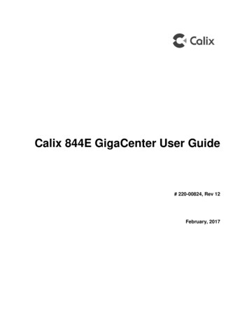
14ODC-200 Expansion Module DescriptionThe Clearfield ODC-200 Expansion Module (EXM) is an environmentally-controlledoutdoor enclosure that mounts adjunct to the base ODC-200 cabinet, allowing the expansionof rack space to the usable sealed capacity of the cabinet. You can install the EXM at thetime of initial deployment of the cabinet, or later as an expansion.The EXM can be mounted on the rear or left side of the base ODC-200 cabinet, as shownbelow.Rear Mount(In-line configuration)Side Mount(L-configuration)The field installable EXM provides the ability to grow the ODC-200 cabinet to support rackspace for: migration of copper loops to fiber drops.additional subscriber fiber distribution endpoints.additional copper line protection.a secondary or alternative integrated battery enclosure.The EXM offers an ideal platform for migrating copper access services to fiber accessinfrastructure and electronics, supporting an equal concentration of copper protection blocksand fiber distribution frames.Proprietary Information: Not for use or disclosure except by written agreement with Clearfield.
15Clearfield also offers an ODC-200 EXM Riser that is used when a Battery Riser is alsomounted under the ODC-200 cabinet. This is an environmentally-controlled outdoorenclosure that mounts under the base of the ODC-200 ODC-200 EXM.Proprietary Information: Not for use or disclosure except by written agreement with Clearfield.
16Cabinet and Expansion Module ViewsViews of the base ODC-200 cabinet and Expansion Module (EXM) follow.Base Cabinet Front CompartmentThe base cabinet front compartment provides 19 inches of vertical rack space (9RU), andhouses the cabinet power system and electronics equipment. The cabinet power systemconsists of an AC load center or AC junction box and DC rectifier shelf (local powerconfigurations), or a 190/-48 VDC converter shelf (remote power configurations). TheClearfield equipment typically includes up to nine Clearfield service units.ODC-200 Front(local power)Proprietary Information: Not for use or disclosure except by written agreement with Clearfield.
17Base Cabinet Side CompartmentThe base cabinet side compartment provides access to the cable entry locations, main groundbar, and fiber management or copper line protection. For fiber access, the fiber managementaccessories may vary greatly according to the ordered options. For copper access, the lineprotection may include up to eight 50-pair protection blocks. The side compartment alsohouses an internal battery enclosure for local power configurations. The battery enclosuresupports an optional battery heater.Proprietary Information: Not for use or disclosure except by written agreement with Clearfield.
18Expansion Module CompartmentThe EXM compartment provides access to cable entry locations and rack space to supportadditional fiber management or copper line protection. For fiber access, the fibermanagement accessories may vary greatly according to the ordered options. For copperaccess, the line protection may include up to eight 50-pair protection blocks. The EXMcompartment also houses a secondary or alternative interior battery enclosure for local powerconfigurations. The battery enclosure supports an optional battery heater.Proprietary Information: Not for use or disclosure except by written agreement with Clearfield.
19Cabinet Side and Expansion Module CompartmentsA view of an in-line configuration follows, with the EXM mounted on the rear of the ODC200 cabinet.Proprietary Information: Not for use or disclosure except by written agreement with Clearfield.
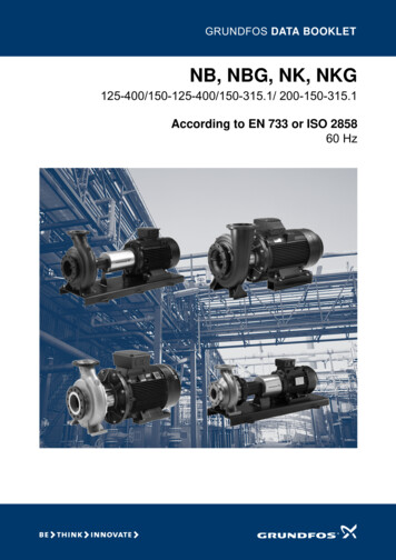
20Cabinet and Expansion Module Dimensions andWeightsDimensions and weights for the base ODC-200 cabinet and Expansion Module (EXM)follow.Cabinet Dimensions and WeightsThe external dimensions of the base ODC-200 cabinet are shown below.DimensionMeasurement (SAE)Measurement (Metric)Height36 inches91 cmWidth24 inches61 cmDepth48 inches122 cmFrontProprietary Information: Not for use or disclosure except by written agreement with Clearfield.
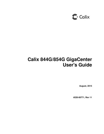
21SideThe approximate shipping weight of the base ODC-200 cabinet is shown below.Configuration OptionsEquipped with protection panelsand internal battery enclosureWeight (SAE)Weight (Metric)290 lb132 kgProprietary Information: Not for use or disclosure except by written agreement with Clearfield.
22Expansion Module Dimensions and WeightsThe external dimensions of the EXM are shown below.DimensionMeasurement (SAE)Measurement (Metric)Height36 inches91 cmWidth24 inches61 cmDepth28.6 inches74 cmMating SideFrontThe approximate shipping weight of the (empty) EXM is shown below.Weight (SAE)Weight (Metric)50 lb23 kgProprietary Information: Not for use or disclosure except by written agreement with Clearfield.
23In-Line Configuration DimensionsThe external dimensions of the in-line configuration are shown below, with the EXMmounted on the rear of the ODC-200 cabinet.FrontSideProprietary Information: Not for use or disclosure except by written agreement with Clearfield.
24L-configuration DimensionsThe external dimensions of the L-configuration are shown below, with the EXM mounted onthe side of the ODC-200 cabinet.FrontRearProprietary Information: Not for use or disclosure except by written agreement with Clearfield.
25SideNote: For clearance and space requirements when mounting the EXM on the rear or side ofthe base ODC-200 cabinet, refer to Space Requirements (on page 31).Proprietary Information: Not for use or disclosure except by written agreement with Clearfield.
Chapter 2Installation ConsiderationsThis chapter provides general considerations for cabinet installation. Review this informationbefore starting the cabinet installation process.Topics CoveredThis chapter covers the following topics: Installation process overviewInstallation guidelinesSpace requirementsGeneral safety recommendationsInstallation kit contentsUser-supplied itemsCabling requirementsProprietary Information: Not for use or disclosure except by written agreement with Clearfield.
28Installation Process OverviewThe cabinet installation process involves the following high-level steps:Proprietary Information: Not for use or di
This document provides a general installation practice for the Clearfield ODC-200 outdoor cabinet. This document also provides a general description of the cabinet and its subsystems, guidance for planning, site preparation, power installation, splicing to the outside plant, component installation and expansion, and cabinet maintenance.