Transcription
FM 5-428 Chptr 7 MasonryPART TWOMasonry7-1. The original idea of masonry was nothing more than placing stones in an orderly fashion normally bylaying them in rows. As time continued, with improved quality and type of materials available, thisorderly lying of stone has progressed into laying them with the use of masonry cements that bonds themtogether. Part two of this manual covers basic tools and equipment, properties, and mixing of mortar.Concrete masonry will include the characteristics of concrete blocks, construction procedures, and rubblestone masonry. The characteristics of brick, and brick laying methods are discussed in the final chapter.Chapter 7Basic Equipment and Components General7-2. Many of the longest-lasting structures in the world are constructed with masonrymaterials, such as stones, bricks, or blocks. Masons are highly skilled people who usespecialized equipment to lay out and construct masonry walls and other building features.Along with erecting these structures, masons are responsible for the care of their tools andequipment. They are also responsible for the correct mixing proportions of the mortar and thesafe erection of scaffolding.SECTION I. MASON'S TOOLS AND EQUIPMENTDEFINITION7-3. Masonry originally meant the art of building a structure from stone. Today, masonrymeans to build a structure from any building materials, such as, concrete blocks, stones,bricks, clay tile products, gypsum blocks, and sometimes glass blocks, that consist of unitsheld together with mortar; The characteristics of masonry work are determined by theproperties of the masonry units and mortar, and the methods of bonding, reinforcing,anchoring, tying, and joining the units into a structure.7-1
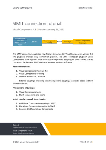
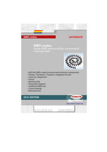
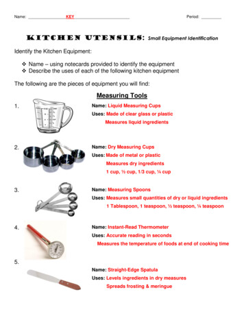
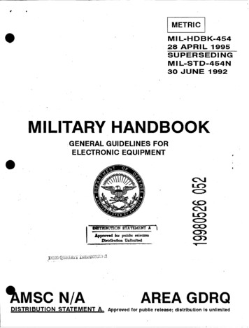
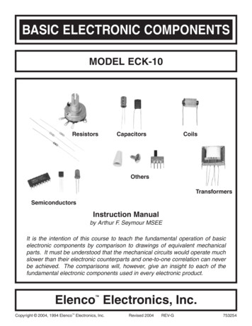
FM 5-428 Chptr 7 MasonryTOOLS7-4. Figure 7-1 shows a set of typical basic mason's tools. Care of the tools are extremelynecessary. Be sure to keep wheelbarrows, mortar boxes, and mortar tools clean becausehardened mortar is difficult to remove. Clean all tools and equipment thoroughly at the end ofeach day or when the job is finished. A full set includes- A trowel. A trowel is used to mix and pick up mortar from the board, to place mortaron the unit, to spread mortar, and to tap the unit down into the bed. A common trowelis usually triangular in shape ranging in size up to about 11 inches long and from 4 to 8inches wide. Its length and weight depend on the mason. Generally, short, wide trowelsare best because they do not put too much strain on the wrist. Trowels used to pointand strike joints are smaller, ranging from 3 to 6 inches long and 2 to 3 inches wide. A chisel or bolster. A chisel is used to cut masonry units into parts. A typical chisel is 21/2 to 4 1/2 inches wide. A hammer. The mason's hammer has a square face on one end and a long chisel peenon the other. It weighs from 1 1/2 to 3 1/2 pounds. It is used to split and rough-breakmasonry units. A jointer. As its name implies, this tool is used to make various mortar joints. Thereare several different types of jointer-rounded, flat, or pointed, depending on the shapeof the mortar joint you want. A square. The square that is shown in Figure 7-2 below is used to measure right anglesand to lay out corners. A mason's level. The level is used to plumb and level walls. A level ranges from 42 to48 inches in length and is made from either wood or metal. Figure 7-2 shows a level inboth the horizontal and vertical positions. When you place it on the masonryhorizontally and the bubble falls exactly in the middle of the center tube, the masonryis level. When you place the level against the masonry vertically and the bubbles fallexactly in the middle of the two end tubes, the masonry is plumb. A straightedge. A straightedge, shown in Figure 7-2, can be any length up to 16 feet,from 1 1/8 inches to 1 1/2 inches thick, and the middle portion of the top edge from 6to 10 inches wide. The middle portion of the top edge must be parallel to the bottomedge. Use a straightedge to extend a level to either plumb or level distances longer thanthe level length. Miscellaneous tools. Other mason's tools and equipment include shovels, mortar hoes,wheelbarrows, chalk lines, plumb bobs, and a 200-foot ball of good quality mason'sline.7-2
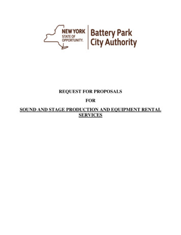
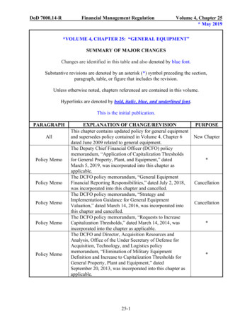
FM 5-428 Chptr 7 MasonryFigure 7-1. Basic Mason's ToolsEQUIPMENT7-5. Mortar is mixed by hand in a mortar box. It should be as watertight as possible. A mortarboard (see Figure 7-3) can range from 3 to 4 feet square. Wet down a mortar boardthoroughly before placing any mortar on it to prevent the wood from drying it out andabsorbing moisture from the mortar. Figure 7-3 shows the proper way to fill a mortar board.Note the mounds of mortar in the center of the board; this minimizes drying. After filling the7-3
FM 5-428 Chptr 7 MasonryFigure 7-2. Square, mason's level, and straightedgemortar board, keep the mortar rounded up in the center of the board and the outer edges of theboard clean. Any mortar spread in a thin layer dries out quickly, and lumps form in it. Be sureto maintain the proper mortar consistency at all times.7-4
FM 5-428 Chptr 7 MasonryFigure 7-3. Motar Box and mortar board7-5
FM 5-428 Chptr 7 MasonrySECTION II. MORTARDESIRABLE PROPERTIES7-6. Good mortar is necessary for good workmanship and good masonry service because itmust bond the masonry units into a strong well-knit structure.BOND CONSIDERATIONS7-7. The mortar that bonds concrete blocks,bricks, or clay tiles together will be the weakestpart of the masonry unless you mix and apply it properly. When masonry leaks areencountered, they are usually through the mortar joints. The strength of masonry and itsresistance to rain penetration depends largely on the strength of the bond between themasonry unit and the mortar. Various factors affect bond strength including the type andquantity of mortar, its workability or plasticity, its water retentivity, the surface texture of themortar bed, and the quality of workmanship in laying the units. You can correct irregularbrick dimensions and shape with a good mortar joint.PLASTICITY7-8. Mortar must be flexible enough to work with a trowel. You can obtain good plasticity orworkability by Using mortar having good water retentivity. Using the proper grade of sand and thoroughly mixing. Using less cementitious materials.Mortar properties depend largely upon the type of sand the mortar contains. Clean, sharp sandproduces excellent mortar; too much sand causes mortar to segregate, drop off the trowel, andweather poorly.WATER RETENTIVITY7-9. Mortar property resists rapid water loss to highly absorbent masonry units. Mortar musthave water to develop the bond. If it does not contain enough water, the mortar will have poorplasticity and workability and the bond will be weak and spotty. Sometimes you must wet thebrick to control water absorption before applying mortar, but never wet concrete masonryunits.STRENGTH AND DURABILITY7-10. The type of service that the masonry must give determines the mortar's strength anddurability requirements. For example, walls subject to severe stresses or to severe weathering7-6
FM 5-428 Chptr 7 Masonrymust be laid with more durable, stronger mortars than walls for ordinary service. Table 7-1below gives mortar mix proportions that provide adequate strength and durability for theconditions listed. You can convert the unit volume proportions to weight proportions bymultiplying the unit volumes given by the weight per cubic foot of the materials. Thosespecifications are-Masonry cement --------------------------- Weight printed on bagPortland cement ---------------------------- 94 lbHydrated lime ------------------------------ 50 lbMortar sand, damp and loose -------------- 85 lbTable 7-1. Recommended mortar mix proportions by unit volumeType of ServicesOrdinaryCementHydratedLimeMortarSand inDamp,LooseConditions1 unit masonry cement1/2 to 1 1/4or 1 unit portlandcement2 1/4 to 34 1/2 to 6Isolated piers subjected to extremely1 unit masonryheavy loads, violent winds, earthquakes, cement* plus 1 unitor severe frost actionportland cement or1 unit portland cement4 1/2 to 60 to 1/42 1/4 to 3*ASTM specification C91 type II.TYPES OF MORTAR7-11. The following mortar types are proportioned on a volume basis: Type M mortar consist of one part portland cement, 1/4 part hydrated lime or limeputty and, 3 parts sand or 1 part portland cement, 1 part type II masonry cement, and 6parts sand. Type M mortar is suitable for general use but is recommended specificallyfor below-grade masonry that contacts earth, such as foun-dations, retaining walls, andwalks. Type S mortar consist of one part portland cement, 1/2 part hydrated lime or limeputty, and 4 1/2 parts sand, or 1/2 part portland cement, 1 part type II masonry cement,and 4 1/2 parts sand. Type S mortar is also suitable for general use, but isrecommended where high resistance to lateral forces is required. Type N mortar consist of one part portland cement, 1 part hydrated lime or lime putty,and 6 parts sand, or 1 part type II masonry cement and 3 parts sand. Type N mortar is7-7
FM 5-428 Chptr 7 Masonry suitable for general use in above- grade exposed masonry where high compressiveand/or lateral strengths are not required.Type O mortar consist of one part portland cement, 2 parts hydrated lime or lime putty,and 9 parts sand, or 1 part type I or type II masonry cement and 3 parts sand. Type Omortar is recommended for load-bearing, solid-unit walls when the compressivestresses do not exceed 100 psi, and the masonry is not subject to freezing and thawingin the presence of a lot of moisture.STORING MORTAR MATERIALS7-12. Store all mortar materials, except sand and slaked quicklime, in a dry place. Sand andlime should be covered to prevent excessive losses or gains of surface moisture.MIXING MORTAR7-13. When blending or mixing mortar, always use the best consistency for the job.MACHINE MIXING7-14. Mix large quantities of mortar in a drum-type mixer, like a concrete mixer. Mix aminimum of 3 minutes. Place all dry ingredients in the mixer first, mix them for 1 minutebefore adding the water.HAND MIXING7-15. Mix small amounts of mortar by hand in a mortar box (see Figure 7-3). Mix allingredients thoroughly to obtain a uniform mixture. Mix all dry materials together first beforeadding water. Keep a steel drum of water close to the mortar box to use as the water supply.Use a second drum of water to store shovels and hoes when not in use.MORTAR MIXING WITH LIME PUTTY7-16. When machine mixing, measure the lime putty using a pail and place it into the skip ontop of the sand. When hand mixing, add the sand to the lime putty. Wet pails before placingmortar in them and clean them immediately after emptying them.WATER QUALITY7-17. Mixing water for mortar must meet the same requirements as mixing water forconcrete. Do not use water con-taining large amounts of dissolved salts, because the salts willcause efflorescence and weaken the mortar.RETEMPERING MORTAR7-18. The workability of any mortar that stiffens on the mortar board due to evaporation byremixing can be restored. Add water as necessary, but discard any mortar stiffened by initialsetting. It is difficult to tell the cause of stiffening; a practical guide is to use mortar within 27-8
FM 5-428 Chptr 7 Masonry1/2 hours after the original mixing when the air temperature is 80 F or higher, and within 31/2 hours when the air temperature is below 80 F. Discard any mortar not used within theselimits.ANTIFREEZE MATERIALS7-19. Do not use an admixture to lower the freezing point of mortar during winterconstruction. The quantity of antifreeze materials necessary to lower the freezing point ofmortar to any appreciable degree is so large that it would seriously impair the mortar'sstrength and other desirable properties. Never use frozen mortar; freezing destroys itsbonding ability.ACCELLERATORS7-20. Make a trial mix to find the percentage of calcium chloride that gives the desiredhardening rate. Do not add more than 2 percent calcium chloride, by weight of cement tomortar, to accelerate its hardening rate and increase early strength. Do not add more than 1percent calcium chloride to masonry cements. Calcium chloride should not be used forsteel-reinforced masonry. You can also accelerate hardening rate in mortars withhigh-early-strength portland cement.REPAIRING AND TUCK-POINTING7-21. Use the mortar mixes given in Table 7-1 when repairing and tuck-pointing old masonrywalls. Compact the joints thoroughly by tooling after the mortar partially stiffens.SECTION III. SCAFFOLDINGCONSTRUCTION AND SAFETY7-22. Extreme care should be taken in building scaffolds because lives depend on them. Userough lumber for wood scaffolding. Never nail scaffolding in a temporary manner; alwaysnail it securely. When you no longer need the planks at a lower level, remove them to avoidfalling mortar splash.TYPES OF SCAFFOLDING7-23. A scaffold is a temporary, movable platform built with planks to support workers andmaterials. It allows bricklayers to work at heights not reachable when standing on the floor orground. Scaffolds can be used in several functions and come in different sizes and heights.TRESTLE SCAFFOLD7-24. Use a trestle scaffold shown in Figure 7-4 when laying bricks from the inside of a wall.Erect the scaffold when the wall reaches a height of 4 or 5 feet. The height of the trestlesshould range from 4 to 4 1/2 feet. The planks should be made using 2 by l0s. Place the trestleat least 3 inches from the wall so that it does not press against the newly laid bricks and force7-9
FM 5-428 Chptr 7 Masonrythem out of line. Build the wall to the next floor level working from the scaffold. When therough flooring for the next floor is in place, repeat the procedure.Figure 7-4. Trestle scaffoldFOOT SCAFFOLD7-25. When reaching lower than a trestle scaffold permits, use a foot scaffold like the oneshown in Figure 7-5. Place 2 by 10 planks on blocks supported by the trestle scaffold. A footscaffold should not exceed 18 inches in height.Figure 7-5. Foot scaffoldPUTLOG SCAFFOLD7-26. A putlog scaffold (see Figure 7-6) reaches from the ground to the height required. Itsuprights are 4 by 4s supported on a 2 by 12 by 12 plank for bearing on the soil. Space the7-10
FM 5-428 Chptr 7 Masonryuprights on 8-foot centers and allow 4 1/2 feet of space between the wall and the uprights, asshown in Figure 7-6. The putlog is 3-by 4-inch lumber that spans the gap between the walland the ledger. One end of the putlog rests on top of the ledger and against the 4 by 4uprights, while the other end fits into the wall (one brick is omitted to make an opening forit). Do not fasten the putlog to the ledger. Place five 2 by 12 planks on top of the putlog toform the scaffold platform. Do not nail the planks to the putlog. Two ways to use stays are Tie the uprights to the wall with stays. You can either pass the stays through a windowopening and fasten them to the inside structure or use spring stays as shown in Figure7-6. To make spring stays, omit one brick from the wall and insert the ends of two 2 by6s in the opening. Then insert a brick between the 2 by 6s and force the brick towardthe wall. Bring the other ends of the 2 by 6s together and nail them securely to theledger. Use the putlog as a stay. You can also use the putlog as a stay by driving a woodwedge above the putlog into its hole in the wall. Then, nail the wedge to the putlog andnail the putlog to the ledger. Install longitudinal cross bracing as shown in Figure 7-6.Figure 7-6. Putlog scaffoldOUTRIGGER SCAFFOLD7-27. An outrigger scaffold (see Figure 7-7) consists of a wood outrigger beam projectingfrom a window sill that supports 2 by 10 planks. Figure 7-7 shows how to brace a woodbeam, but if you use a steel outrigger beam, fasten it to the structure's formwork usingthreaded U-bolts.7-11
FM 5-428 Chptr 7 MasonryFigure 7-7. Outrigger scaffoldPREFABRICATED STEEL SCAFFOLD7-28. If it is available, use prefabricated steel scaffolding (see Figure 7-8) rather than buildinga scaffold.7-12
FM 5-428 Chptr 7 MasonryFigure 7-8. Prefabricated steel scaffoldMATERIALS TOWER7-29. Use a steel material tower if construction details are available because it is easier toerect and generally safer. Otherwise, you can construct a wood tower to hoist materials to theworking height, like the one shown in Figure 7-9. Locate the tower where you can bringmaterials to it over the shortest haul, but far enough away from the structure to clear anyexternal scaffolding. A clearance of 6 feet 8 inches is enough for scaffold platforms 5 feetwide. Construct the tower footing using two 2 by 12s, 2 feet long, placed under each 4 by 4post. The height of the tower should extend at least 15 feet above the highest point where youneed a landing. Then construct landings extending from the tower to the floors and scaffoldplatforms as needed. Use 2 by 10s or 2 by 12s for the landings.7-13
FM 5-428 Chptr 7 MasonryFigure 7-9. Materials tower and elevator7-14
FM 5-428 Chptr 7 MasonryELEVATOR7-30. Figure 7-9 also shows the elevator, rope, and pulley arrangement that serves thematerials tower. Note the guides at the base of the elevator that fit onto the guides running upfrom the base of the tower.7-15
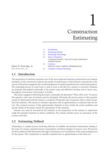
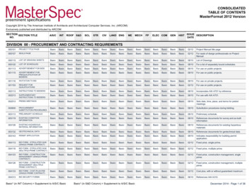
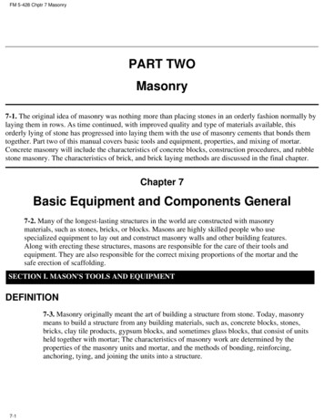
FM 5-428 Chptr 8 Concrete MasonryChapter 8Concrete Masonry8-1. When portland cement, water, and suitable aggregates, such as sand, gravel, crushedstone, cinders, burned shale, or slag, are mixed and formed into individual pieces to be usedin laying up walls and other structural details, the pieces thus formed are known as unitmasonry, or units. However, most masons refer to them as concrete blocks. Concrete blockswill vary in size and shape as well as style. They are typically used for house foundations,decorative blocks for strong garden, or retaining walls. Rubble stone masonry is strong,durable, and offers an incomparable beauty and range of effect. Construction of concretemasonry is time consuming and requires highly skilled personnel.SECTION I. CHARACTERISTICS OF CONCRETE BLOCKNATURE AND PHYSICAL PROPERTIES8-2. A concrete block is a masonry unit that either contains single or multiple hollows, or issolid. It is made from conventional cement mixes and various types of aggregate, includingsand, gravel, crushed stone, air-cooled slag, coal cinders, expanded shale or clay, expandedslag, volcanic cinders (pozzolan), pumice, and scoria (refuse obtained from metal orereduction and smelting). The term concrete blocks was formerly limited to only hollowmasonry units made with such aggregates as sand, gravel, and crushed stone. But today theterm covers all types of concrete blocks (both hollow and solid) made with any kind ofaggregate. Concrete blocks are also available with applied glazed surfaces, various pierceddesigns, and a wide variety of surface textures. Although a concrete block is made in manysizes and shapes (see Figure 8-1 below) and in both modular and nonmodular dimensions, itsmost common unit size is 7 5/8 by 7 5/8 by 15 5/8, known as 8- by 8- by 16-inch blocknominal size. All concrete blocks must meet certain specifications covering size, type,weight, moisture content, compressive strength, and certain other special characteristics.Concrete masonry is an increasingly important type of construction due to technologicaldevelopments in both the manufacture and the use of concrete blocks. Properly designed andconstructed concrete masonry walls satisfy many building requirements, including fireprevention, safety, durability, economy, appearance, utility, comfort, and acoustics.8-1
FM 5-428 Chptr 8 Concrete MasonryFigure 8-1. Typical unit sizes and shapes of concrete masonry units8-2
FM 5-428 Chptr 8 Concrete MasonryFigure 8-1. Typical unit sizes and shapes of concrete masonry units (continued)CONCRETE BLOCK MASONRY UNIT8-3. Concrete blocks are used in all types of masonry construction, such as- Exterior load-bearing walls (both below and above grade). Interior load-bearing walls. Fire walls and curtain walls. Partitions and panel walls. Backing for bricks, stones, and other facings. Fireproofing over structural members. Fire-safe walls around stairwells, elevators, and enclosures.8-3
FM 5-428 Chptr 8 Concrete Masonry Piers and columns.Retaining walls.Chimneys.Concrete floor units.TYPES OF UNITS8-4. The main types of concrete masonry units are- Hollow, load-bearing concrete block. Solid, load-bearing concrete block. Hollow, nonload-bearing concrete block. Concrete building tile. Concrete brick.8-5. The load-bearing types of blocks have two grades. Grade N is for general use, such asexterior walls both above and below grade that may or may not be exposed to moisturepenetration or weather, and for back-up and interior walls. Grade S is for above-grade exteriorwalls with weather-protective coating and for interior walls. The grades are furthersubdivided into two types: type I moisture-controlled units (for use in arid climates) N-I andS-I, and type II nonmoisture-controlled units N-II and S-II.HEAVYWEIGHT ANDF LIGHTWEIGHT UNITS8-6. The concrete masonry units made with either heavyweight or lightweight aggregates arereferred to as such. A hollow, load-bearing concrete block is 8 by 8 by 16 inches withnominal-size weight from 40 to 50 pounds. These types of blocks are normally made withheavyweight aggregate such as sand, gravel, crushed stone, or air-cooled slag. The same typeand nominal-size block weighs only from 25 to 35 pounds when made with coal cinders,expanded shale, clay, slag, volcanic cinders, or pumice. Your choice of masonry unitsdepends on both availability and the requirements of the intended structure.SOLID AND HOLLOW UNITS8-7. ASTM specifications defines a solid concrete block as having a core area not more than25 percent of the gross cross-sectional area. Most concrete bricks are solid and sometimeshave a recessed surface like the frogged brick shown in Figure 8-1 above. In contrast, ahollow concrete block has a core area greater than 25 percent of its gross cross-sectionalarea--generally 40 to 50 percent.SIZES AND SHAPES8-8. Concrete masonry units are available in many sizes and shapes to fit differentconstruction needs. Both full- and half-length sizes are shown in Figure 8-1. Because concreteblock sizes usually refer to nominal dimensions, a unit actually measuring 7 5/8 by 7 5/8 by15 5/8 inches is called an 8- by 8- by 16-inch block. When laid with 3/8-inch mortar joints,8-4
FM 5-428 Chptr 8 Concrete Masonrythe unit will then occupy a space exactly 8 by 8 by 16 inches. Before designing a structure,contact local manufacturers for a schedule of their available unit sizes and shapes.MAKING BLOCKS BY MACHINE8-9. To precast concrete blocks, use a power-tamping machine available from severalmanufacturers. Tamp the concrete into the mold, then immediately strip off the mold. Thisway you can make many blocks rapidly using a single mold. The mix should be dry enoughfor the block to retain its shape.MAKING BLOCKS BY HAND8-10. To precast blocks by hand, pour concrete of fluid consistency into sets of iron molds,then strip off the molds when the concrete hardens. This procedure makes dense block withlittle labor; however, it requires a large number of molds.MAKING WEATHER-EXPOSED BLOCKS8-11. Make blocks subject to weathering with a concrete mix of at least six sacks of cementper cubic yards of mix. When using lightweight, porous aggregate, premix it with water for 2minutes before adding the cement.CURING CONCRETE BLOCKS8-12. Steam is the best way to cure concrete blocks because it takes less time. Concreteblocks cured in wet steam at 125o F for 15 hours have 70 percent of their 28-day strength. Ifsteam is not available, cure the blocks by protecting them from the sun and keeping themdamp for 7 days.SECTION II. CONSTRUCTION PROCEDURESMODULAR COORDINATION AND PLANNING8-13. Modular coordination is when the design of a building, its components, and thebuilding-material units all conform to a dimensional standard based on a modular system.Modular measure is the system of dimensional standards for buildings and buildingcomponents that permit field assembly without cutting. The basic unit is a 4-inch cube thatallows a building to be laid around a continuous three-dimensional rectangular grid having4-inch spacing. The modular system of coordinated drawings is based on a standard 4-inchgrid placed on the width, length, and height of a building, as shown in Figure 8-2.8-5
FM 5-428 Chptr 8 Concrete MasonryFigure 8-2. Elements of modular designStep 1. Use the grid on preprinted drawing paper for both small-scale plans and large-scaledetails. Do not use drawing paper with a scale less than 3/4 inch which equals 1 foot to showgrid lines at 4-inch spacing.Step 2. Select a larger planning module that is a multiple of 4 inches. For floor plans andelevations, for example, the module may be 2 feet 8 inches, 4 feet, 5 feet, 6 feet 4 inches, andso forth.Step 3. Show materials actual size, or to scale, and locate them on or related to a grid line byreference dimensions. Dimensions falling on grid lines are shown by arrows; those not fallingon grid lines, by dots (see Figure 8-2 above). 8-6Maintain constant awareness of standard modular dimensions in planning, and preplanthe work to make use of as many standard- sized building materials as possible. Suchplanning saves considerable labor, time, and materials.Make maximum use of full- and half-length units when laying out concrete masonrywalls to minimize cutting and fitting units on the job.Plan the wall length and height, the width and height of openings, and wall areasbetween doors, windows, and corners to use full- and half-size units as shown in Figure8-3. Remember that window and door frames must have modular dimensions to fitmodular full- and half-size masonry units.Keep all horizontal dimensions in multiples of nominal full-length masonry units. Bothhorizontal and vertical dimensions should be designed in multiples of 8 inches. Table8-1 below gives the nominal lengths of modular-concrete masonry walls in the number
FM 5-428 Chptr 8 Concrete Masonry of stretchers, and Table 8-2 below gives the nominal heights of modular-concretemasonry walls in the number of courses.Plan the horizontal dimensions in multiples of 8 inches (half-length units) and thevertical dimensions in multiples of 4 inches, when using 8 by 4 by 16 blocks. If thewall thickness is either greater or less than the length of one half-length unit, use aspecial length unit at each corner in each course.Figure 8-3. Planning concrete masonry wall openingsTable 8-1. Nominal length of modular-concrete masonry walls in stretchersNumberofStretchers8-7Nominal Length of Concrete Masonry WallsUnits 15 5/8" Long andHalf Units 7 5/8" LongWith 3/8" Thick HeadJointsUnits 11 5/8" Long andHalf Units 5 5/8" LongWith 3/8" Thick HeadJoints11 1/221' 4"2' 0"2' 8"1' 0"1' 6"2' 0"2 1/233 1/23' 4"4' 0"4' 8"2' 6"3' 0"3' 6"
FM 5-428 Chptr 8 Concrete Masonry44 1/255' 4"6' 0"6' 8"4' 0"4' 6"5' 0"5 1/266 1/27' 4"8' 0"8' 8"5' 6"6' 0"6' 6"77 1/289' 4"10' 0"10' 8"7' 0"7' 6"8' 0"8 1/299 1/211' 4"12' 0"12' 8"8' 6"9' 0"9' 6"1010 1/21113' 4"14' 0"14' 8"10' 0"10' 6"11' 0"11 1/21212 1/215' 4"16' 0"16' 8"11' 6"12' 0"12' 6"1313 1/21417' 4"18' 0"18' 8"13' 0"13' 6"14' 0"14 1/2152019' 4"20' 0"26' 8"14' 6"15' 0"20' 0"NOTE: Actual wall length is measured from outside edge to outsideedge of units and equals the nominal length minus 3/8" (one mortarjoint).Table 8-2. Nominal height of modular-concrete masonry walls in coursesNumber ofStretchers8-8Nominal Length ofConcreteMasonry Walls
FM 5-428 Chptr 8 Concrete MasonryUnits 75/8"High and3/8"Thick BedJointsUnits 35/8"High and3/8"Thick BedJoints1238"1' 4"2' 0"4"8"1' 0"4562' 8"3' 4"4' 0"1' 4"1' 8"2' 0"74' 8"2' 4"85' 4"2' 8"96' 0"3' 0"106' 8"3' 4"1510' 0"5' 0"2013' 4"6' 8"2516' 8"8' 4"3020' 0"10' 0"3523' 4"11' 8"4026' 8"13' 4"4530' 0"15' 0"5033' 4"16' 8"NOTE: For concrete masonry units 7 5/8" and3 5/8" in height laid with 3/8'' mortar joints.Height is measured from center to center ofmortar joints.8-9
FM 5-428 Chptr 8 Concrete MasonryWALLS AND WALL FOOTINGS8-14. Place masonry wall footings on firm, undisturbed soil having adequate load-bearingcapacity to carry the design load and below frost penetration. Unless local requirements orcodes specify otherwise, make the footings for small buildings twice as wide as the thicknessof the walls they support. Table 8-3 below gives both the unit weights and quantities formodular-concrete masonry walls. Footing thickness equals wall width (see Figure 8-4 below).Table 8-3. Unit weight and quantities for modular concrete masonry wallsActualUnit Size(Width xHeight xLength), inInchesNominalWallThickness, inInchesFor 100 Sq Ft of Walls3 5/8 x 35/8 x 15 5/85 5/8 x 35/8 x 15 5/87 5/8 x 35/8 x 15 59.56663 5/8 x 75/8 x 15 5/85 5/8 x 75/8 x 15 5/87 5/8 x 75/8 x 15 5/811 5/8 x7/5/8 x 2,0502,9503,6004,9006.06.06.06.07777Number ofUnitsAverage Weight of Finished WallHeavyweightAggregate,in Lb*LightweightAggregate,in Lb*Mortar,*in CuFtNOTES: 1. Table is based on 3/8-inch mortar joints.2. Actual weight of 100 sq ft of wall can be computed by formula W (n) 150(M).where-W actual weight of a single unit.n number of units for 100 sq ft of wall.M cu ft of mortar for 100 sq ft of wall.*Actual weight within 7% of average weight. With face-shell mortar bedding. Mortarquantities should include 10% allowance for waste.8-10
FM 5-428 Chptr 8 Concrete MasonryFigure 8-4. Dimensions of masonry wall footingsSUBSURFACE DRAINAGE8-15. If you expect the groundwater level during a wet season to reach the basement floorelevation, place a line of drain tile along the exterior side of the footings. The tile line shouldfall at least 1/2 inch in 12 feet and drain to a suit
1 unit portland cement 0 to 1/4 4 1/2 to 6 2 1/4 to 3 *ASTM specification C91 type II. TYPES OF MORTAR 7-11. The following mortar types are proportioned on a volume basis: Type M mortar consist of one part portland cement, 1/4 part hydrated lime or lime putty and, 3 parts sand or 1 part portland cement, 1 part type II masonry cement, and 6 .