Transcription
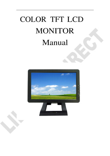
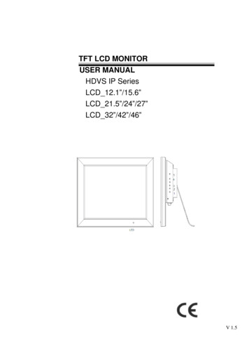
TFT LCD MONITORUSER MANUALHDVS IP SeriesLCD 12.1”/15.6”LCD 21.5”/24”/27”LCD 32”/42”/46”V 1.5
1. Warning.3 2. Safety Precautions.4 3. LCD Monitor Mounting guide.6 4. Monitor Controls .8 5. Connections.10 6. LCD OSD Function.12 7. PC Timing.13 8. Features.13 9. Specification.14 10. Appendixes . Troubleshooting for Display problem . . .17 11. IP Camera Device Side Setting .18 12. HDVS IP Host Side Operation.19 13. HDVS IP Display Setting .21 14. HDVS IP Network Setting .21 15. NTP Setting .22 16. Connect With IP Camera . . . .22 17. Drag to Change Channel Sequence . . . .24 18. Digital Zooming . . .24 19. System Device Setting .25 20. Channel Information . . . .26 21. Recording .27 22. System HDD/e SATA Setting . . 29 23. Troubleshooting for IP Camera Problem . . .302
1. WARNING:TO REDUCE THE RISK OF FIRE OR ELECTRIC SHOCK, DO NOT EXPOSE THIS PRODUCTTO RAIN OR MOISTURE.DO NOT INSERT ANY METALLIC OBJECT THROUGH VENTILATION GRILLS.CAUTION:Explanation of Graphical SymbolsThe lightning flash with arrowhead symbol, within an equilateral triangle, is intendedto alert the user to the presence of uninsulated “dangerous voltage” within the product senclosure that may be of sufficient magnitude to constitute a risk of electricshock to persons.The exclamation point within an equilateral triangle is intended to alert the user to thepresence of important operating and maintenance (servicing) instructions in theliterature accompanying the ---------------Should any liquid or solid object fall into thecabinet, unplug the unit and have it checkedby the qualified personnel before operating itany further.Do not install the unit in an extremely hot orhumid place or in a place subject to excessivedust or mechanical vibration.The unit is not designed to be waterproof.Exposure to rain or water may damage the unit.Unplug the unit from the wall outlet if it is notgoing to be used for several days or more.To disconnect the cord, pull it out by the plug.Never pull the cord Clean the unit with a slightly damp soft cloth.Use a mild household detergent. Never use strongsolvents such as thinner or benzene as they mightdamage the finish of the unit.Allow adequate air circulation to preventinternal heat built-up. Do not place the unit onsurfaces(rugs, blankets, etc.) or near materials Retain the original carton and packing materials(curtains, draperies) that may block thefor safe transport of this unit in the future.ventilation holes.3
2. Safety PrecautionsFederal Communications Commission (FCC) StatementThis Equipment has been tested and found to comply with the limits for aClass B digital device, pursuant to Part 15 of the FCC rules. These limits aredesigned to provide reasonable protection against harmful interference in aresidential installation. This equipment generates, uses and can radiateradio frequency energy and, if not installed and used in accordance with theinstructions, may cause harmful interference to radio communications.However, there is no guarantee that interference will not occur in a particularinstallation.If this equipment does cause harmful interference to radio or television reception,which can be determined by turning the equipment off and on, the user isencouraged to try to correct the interference by one or more of the followingmeasures:-Reorient or relocate the receiving antenna.-Increase the separation between the equipment and receiver.-Connect the equipment into an outlet on a circuit different from thatto which the receiver is connected.-Consult the dealer or an experienced radio/TV technician for help. You are cautioned that changes or modifications not expressly approvedby that party responsible for compliance could void your authority tooperate the equipment.This device complies with Part 15 FCC Rules. Operation is subject to thefollowing two conditions:(1) This device may not cause harmful interference.(2) This device must accept any interference received including interferencethat may cause undesired4
About this user manualThis manual aims at assisting the user on how to operate the monitors described in thismanual.This manual is subject to rigid quality control. However, no guarantee can be given thatmistakes are not present. We reserve the right to make changes to the manual without priornotice.Before operating the appliance, please read this manual carefully and retain it for furtherreference. Verify that all appliance items are included in the delivery. Should items bemissing, do not operate the appliance and contact your local dealer.Never attempt to repair the appliance yourself. This should only be done by qualified servicepersonnel.Improper handling of the appliance will invalidate the warranty.Package ListA. LCD IP MonitorB. Power CordC. User ManualD. 12V Power AdapterE. USB Mousex1x1x1x 1 [Except for the 32”/42”/46”]x15
3. LCD Monitor Mounting GuideA.DesktopAdjust the viewing angle of LCD to fit most comfortable monitoring status.B.Wall mountFree your space with wall mount design.Please follow the fix-hole size in back panel to install the LCD to the wall.12.1”/15.6”/21.5”/24”/27”C. VESA Bracket12.1”/15.6”/21.5”/24”/27”6
VESA Bracket: 32”VESA Bracket: 42”/46”7
4. Monitor 42”/46” Aluminum32”/42”/46” Aluminum8
Key Board1. PowerPush to turn on and turn off the unit.LED Green light: Power onLED Red light: Standby mode.2. / 3. Adjust UP /DOWNUP: Used as UP function. Or Increase value on the OSD Menu.And as a hot key for color adjust function.DOWN: Used as DOWN function. Or Decrease value on the OSD Menu.And as a hot key for auto adjust function.4. Item:Hot key for OSD adjustments of Volume , Contrast, Brightness,, and Red, Green, Blue.5. MenuPush to call out OSD menu. Or Used as Confirm function in OSD Menu.6. SourceSelect input signal from D-SUB, HD,DVI ,and IP.KEY Lock Function:Push “Menu” and “Item” , OSD of screen will show “Key Lock on”, Into key lock mode.And push again , OSD of screen will show “Key Lock off “, Into key unlock mode.9
5. Connections: HDVS IP Series12.1”/15.6”/21.5”/24”/27”2345671: e-SATA2: RJ-45 (Ethernet Interface)3: USB IN *2 (USB Mouse/Record Backup Connector)4: DC 12V IN5: DVI IN6: Full HD IN7: VGA IN8: AUDIO R/L IN9: Earphone OUT1089
32”/42”/46”2345671: e-SATA2: RJ-45 (Ethernet Interface)3: USB IN *2 (USB Mouse/Record Backup Connector)4: DC 12V OUT5: DVI IN6: Full HD IN7: VGA IN8: AUDIO R/L IN9: Earphone OUT1189
6. LCD OSD FunctionColorImage SettingOSD MenuSignal SourceAudioMisc.BackColor:ContrastAdjust background black level of the screen image.BrightnessAdjust fore ground white level of the screen image.Color AdjustAdjust Red, Green, Blue, color deepness for Users.Color TempAdjust color temperatures for users.9300, 6500, 5800, sRGB, USERBackExit OSD menu.Image Setting:ClockAdjust image distortion appearing as vertical or “noise” on the screen.PhaseAdjust image distortion appearing as horizontal or “noise” on the screen.SharpnessAdjust the clarity and focus of the screen images.H. PositionMove the screen image left or right.V. PositionMove the screen image up and down.BackExit OSD menu.OSD Menu:OSD H. PosMove the OSD menu position left or right.OSD V. PosMove the OSD menu position up or down.OSD TimerSet the OSD menu display time.LanguageSelect the desired language as English, French, German, Spanish,Traditional Chinese Simplified Chinese, and Japanese.BackExit OSD menu.Signal sourceSelect the input signal VGA, HD, DVI, and IP.Back12
Exit OSD menu.AudioVolumeControl built-in speakers' output VolumesMuteDisable the unit's sound outputBackExit OSD menu.Misc:Auto AdjustAdjust the best image.Color AdjustAdjust the best image color.ResetReturn to factory default setting.Screen saverUse the manual buttons to on/off the screen saverBack:Exit the OSD menu.7. PC 024@601280*1024@751360*768@601920*1080@608. Features H264 compression formatVGA/ DVI-D and Full HD InputReal-time displaySupport HDMI video output (1920 x 1080 @30)Graphical and text interfaces (GUI)Use Ethernet connection controlSupports up to four network cameras via HUBSupports network protocols TCP/IP, DHCP, DNS, HTTP, SMTPSystem login13
9. SpecificationMonitor modelLCD panelVisible area (mm)Picture formatMax. resolutionPixel dot pitch (mm)ColoursBrightnessContrastResponse time(Tr/Tf)View angle (U/D/L/R)Full HD inputAudio input(R/L)T121-4HDVSL-IP12.1”245.76 x 184.324:31024x7680.297x0.29716.2M500 cd/m² [LED]700 : 135 ms80/80/80/801x Full HD2x (RCA)1x VGA input1x DVI-D inputPC inputEarphone outSpeakerIP Video supportOSD settingNetwork PortUSB PortHDD PortPower inputPower consumptionDimensions (WxHxD) mmWeightOperating temperatureT156-2HDVS-IP15.6“344.1x 193.516: 91920x10800.17925 x 0.17925262K300 cd/m² [LED]600 :13/8 ms60/60/70/701xPhone jack ,3.5ψ2x built-in speaker (2 watt)4x(1280X960) sub(960*576) 4Play4x(1920X1080) sub(960*576) 1Play1x(1920X1080) sub(960*576) 1PlayYes1x RJ45, 10M/100M2x USB 2.0 ports1x e-SATA portAC 100-240V 50/60Hz, Adapter DC 12V/5AApprox. 16 wattApprox. 15 watt299.6 x 238.9 x 57.3401.5x 251 x60.32.3kg3.2kg0 to 40 CSubject to technical changes without prior notice. Error excepted.14
Monitor modelLCD panelVisible area (mm)Picture formatMax. resolutionPixel dot pitch (mm)ColoursBrightnessContrastResponse time(Tr/Tf)View angle (U/D/L/R)Full HD inputAudio input(R/L)T215-1HDVSL-IP21.5“476.6 x 268.116 : 91920 x 10800.248x0.24816.7M250 cd/m² [LED]1000 :11.3/3.7 ms80/80/85/85T240-1HDVSL-IP24“531.3 x 298.816:91920x10800.276.7 x0.276 .716.7M250 cd/m² [LED]1000:11.5/3.5 ms80/80/85/851x Full HD2x (RCA)1x VGA input1x DVI-D inputPC inputEarphone outSpeakerT270-2HDVS-IP27”597.6 x 336.1516:91920x10800.276.7 x0.276 .716.7M300 cd/m² [LED]5000:13.5/5 ms89/89/89/891xPhone jack ,3.5ψ2x built-in speaker (2 watt)4x(1280X960) sub(960*576) 4Play4x(1920X1080) sub(960*576) 1PlayIP Video support1x(1920X1080) sub(960*576) 1PlayOSD settingYesNetwork Port1x RJ45, 10M/100MUSB Port2x USB 2.0 portsHDD Port1x e-SATA portPower inputAC 100-240V 50/60Hz, Adapter DC 12V/5APower consumptionApprox. 24 wattApprox. 27wattApprox. 35wattDimensions (WxHxD) mm 531.2 x 322.5 x 71.2586 x 353.3 x 61.6658 x 396.5 x 63.9Weight5.7 kg5.8 kg7kgOperating temperature0 to 40 CSubject to technical changes without prior notice. Error excepted15
Monitor modelLCD panelVisible area (mm)Picture formatMax. resolutionPixel dot pitch (mm)ColoursBrightnessContrastResponse time(Tr/Tf)View angle (U/D/L/R)Full HD inputAudio input(R/L)T320-2HDVS-IP32“698.4 x 392.816 : 91920 x 10800.36375x 0.3737516.7M350 cd/m² 4x 523.2616 : 91920 x 10800.4845 x0.484516.7M400 cd/m² [LED]4000:16.5ms89/89/89/891x Full HD2x (RCA)1x VGA input1x DVI-D inputPC inputEarphone outSpeakerT460-4HDVS-IP46”1018.08 x 572.7616: 91920 x 10800.53025x 0.530251073.7M500 cd/m² [LED]4000:16.5ms89/89/89/891xPhone jack ,3.5ψ2x built-in speaker (2 watt)4x(1280X960) sub(960*576) 4Play4x(1920X1080) sub(960*576) 1PlayIP Video support1x(1920X1080) sub(960*576) 1PlayOSD settingYesNetwork Port1x RJ45, 10M/100MUSB Port2x USB 2.0 portsHDD Port1x e-SATA portPower inputAC 100-240V 50/60HzPower consumptionApprox. 58 wattApprox. 78wattApprox.107 wattDimensions (WxHxD) mm 761.6 x 454.6 x 93.2 994.6 x 587.2 x 82.7 1081.5 x 635.5 x 80.5Weight13.2 kg23kg25kgOperating temperature0 to 40 CSubject to technical changes without prior notice. Error excepted16
10.Appendixes . Troubleshooting for Display problemThe tables provided below include some problems that the user may encounter while using thedisplay and the corresponding solutions. Please refer to the contents of this section prior tocontacting service personnel.ProblemNo picturePossible Causes1. Is the power cable connected to theunit?2. Is the unit turned on?3. Is the signal cable connected to theunit?4. Is the unit in power saving mode?Solutions1. Make sure the power cable has beenproperly connected to the unit.2. Turn on the unit.3. Make sure the signal cable has beenproperly connected to the unit.4. Press any key on computer keyboard.Strange color1. Is the signal cable connected to the 1. Make sure the signal cable has beenunit?properly connected to the unit.Picturedistortion1. Is the signal cable connected to the 1. Make sure the signal cable has beenunit?properly connected to the unit.2. Make sure the input signal is within2. Is the video input signal within thethe unit's specified frequency range.unit's specified frequency range?1. Have the unit's brightness andcontrast settings been set to thelowest level?1. Adjust brightness and contrastPicture is toodim1. Is the connection of the inputsignal correct?1. Check connection of input signal.2. Make sure the signal cable has beenproperly connected.1. Is the signal cable connected to theunit?2. Has the volume been set to the minlevel?3. Is the audio cable connected to theunit?1. Make sure the signal cable has beenproperly connected to the unit.2. Adjust the volume to an appropriatesetting.3. Make sure the audio cable has beenproperly connected to the unit.Only sound butno pictureOnly picturebut no soundPlease contact the customer service center of your local dealer if you have any questionsregarding the unit after reading the information provided above.17
11.IP Camera Device Side SettingIP Camera Network Configuration Direct connector to a computer. Configure your IP Camera Network settings. Please reference your IP Cameramanual. Run the IE browser and login to setup. To set an IP address for the Camera unit. Disable DHCP setting. Stream Type: Dual (Main and SubStream) Resolution: 2M 1080p;D1 Resolution: 1M 720p;D1 Stream Codec Profiles: H.26418
12.1.HDVS IP Monitor Host Side OperationStart SystemPlug in power cable and connect the RJ-45 LANcable, USB mouse, e-SATA HDD cable (if record theimage) to the HDVS IP Monitor. For the first time whenplug in power cable the HDVS IP Monitor will bootingautomatically.Press the power switch button (on the right rear sideand reference page-9 “Key Board” function), the powerLED will be on and the HDVS IP Monitor will start.Notice: After booting, the video output default tomulti-window output mode. If the booting timeis within the record setting time period, thesystem will auto enable the record function.2.System LoginAfter normal booting, right click to bring the menu,select 【Start】 Login,Input the user name: admin and password blank(default to be blank) in the input box19
After login successfully, system will pop out the Startupwizard UI on the screen. Language: select different language according tothe necessary, after that need restartthe device. Display Setting: The resolution default setting is1024x768; please select the bestresolution according to the monitoror it will affect the image definition. Network Setting: The IP, Subnet Mark, DefaultGateway is HDVS IP Monitor hostside default setting3.IP Channel SettingIP address setting menu, recommend used “Manual” tosetting the IP Channel, and please click “No”4Power off1. Click the power switch at the rear panel can shutdown the device.2. 【Main Menu】 【Power Off】,select 【Yes】(By this way, user need have shutdownauthority)(Suggest to shutdown device in this way, it can avoid damaging the device from v electricitycut-off by accident).Note: Before changing the HDD operation, please shutdown the device and cut the power supplyfirst.20
13.HDVS IP Display SettingClick 【Display】 on the menu bar; Show themenu as the right side:1) Language: select different language accordingto the necessary, after that need restart thedevice.2) Auto Logout: system automatic logout andlock time.3) TV Adjust: adjust the display position.4) Display: set monitor lightness, contrast,saturation and color.5) Resolution: the default setting is 1024x768;please select the best resolution according tothe monitor or it will affect the image definition.6) Rotation interval: Setup the time interval ofrotation. Tick “Enable SEQ” to start rotation.14.HDVS IP Network SettingConnect HDVS IP Series with network cable toLAN switch. After power on, click 【Setting】on themenu bar Network Network Setting to entersetting menu, set HDVS IP address, subnet mask,and gateway and so on. Then use PC to run pingcommand to check HDVS IP has connected withLANNotice: IP address might conflict with each other,please set the gateway correctly, or HDVS might fail to work.Please ensure all the IP addresses in LAN are unique.Remote port setting: the default is 5050, if there are several IPs in the LAN, need to change thisport is for login IP by IE, CMS. Login IP by mobile, the port should be 3 based on the device port.HTTP port: the default port is 80, suggest modifying it. This port is for login IP by IE, input IPaddress or domain name; need to add colon and HTTP port number.21
Example: show as the above right picture, access IP by IE in LAN, first add 2 forwarding rules inthe router, the IP address is 192.168.1.188, the forwarding ports are 5050-5053, 80. Please inputhttp://192.168.1.188:80 at IE browser and download ActiveX, then close the IE before install theActiveX, after installing it successfully, then reopen IE with http://192.168.1.188:80, it will showlogin menu, input device port:5050, user name: admin, no password, can access IP.If access IP by IE in WAN, please use static IP or dynamic domain name, the operation is same asLAN.15.NTP SettingIP camera time synchronizationTo click 【Setting】on the menu bar Network NTP Setting to enter settingServer Address:” pool.ntp.org”Note: Time is not synchronized to avoiderrors arising from IP camera.16.Connect with IP CameraRight click to select 【IP Channel Setting】 【Manual】click “Search” button The HDVS IPMonitor will search out all IP cameras in the LAN, it will take 18-30 seconds, after finishing theconfiguration, click Save to logout, then the image will come out.22
Onvif device select UDP network Type.IPCAM device select TCP network Type.Example:To click “Save” and click “Exit“ button than the image will come out.23
17.Drag to Change channel SequenceDuring real video surveillance, it’s very important to have preview channel position of IPC image.Simple image dragging could not meet the need of multi-channel simultaneous playback and it’sfrustrating to match channel position respectively when searching. Dragging channel sequencecan better solve this problem.Right Mouse to click 【IP channel setting】, choose【drag to change channel sequence】18.Digital ZoomingDuring image preview and playback, roll mouseroller to do digital zooming, it zoom the image asmouse pointer as the center. The max can do 15Xzooming. Drag the zoomed image by mouse to seeimage detail.24ZoomIn
19.System Device SettingDevice ParameterClick【Setting】 Device Device info to check device spec, information and time settingAttention: select mode according the connected IP camera channels and resolution, after changethe model, click save and reboot the device.When the image is good in 4CH screen modes, after double click the image to zoom, the image isstuck or become black screen change to 1080p mode can solve it.720p : 4x(1280X960) sub(960*576) 4Play1080p: 4x(1920X1080) sub(960*576) 1Play1080p: 1x(1920X1080) sub(960*576) 1Play25
20.Channel InformationClick【Setting】 Channel Video Parameters, to adjust IP camera preview and recordingresolution.1) Encoding Type:Main Stream (Normal), Sub Stream, Main Stream (Event) for selectionMain Stream: double click to show single image or full screens image are main stream, alsorecording playback is main stream.Sub Stream: screens display are using sub stream, IE or mobile viewing are sub stream also.Main Stream (Event): motion detection and alarm trigger recording are using this.2) Stream Type: there are video, video & audio two types for selection.When connect with audio, please select video & audio mode, or there will be no audio whenplayback.3) Resolution: IP will get IP camera main stream and sub stream resolution automatically, whenthe image is not good, adjust from here according to necessery.4) Bitrate Type: set variable bit rate(VBR) and constant bit rate(CBR).5) Bitrate: set the bit rate upper limit for coding.main stream are 1080P: 6000kbps, 720P: 4000kbps ;set the bit rate upper limit for coding sub stream is 512-1024kbps.6) Frame Rate: suggest to set full frame 25/30.7) Video Quality: suggest to select highest.When all the IP cameras connected with IP are the same brand, after finish setting 1st channel,click Copy To to apply the setting to all channels is capable, then click Save.26
21.RecordingManual Recording & Schedule RecordManual RecordingRight click to bring main menu, click【Record】to enter record setting.Manual recording has the highest priority, after performing Manual,the corresponding channel will begin recording.Schedule RecordRight click to bring main menu, click【Setting】 Channel Schedule Record, the default settingis 24 hours recording, users can set therecording plan according to the necessary andcopy it to other channelNote: If IP stop recording in a regular time,please check schedule record status, theschedule might be get wrong, please adjustthem to manual record.27
PlaybackRight click to bring main menu, click【playback】to open the window:Channel Select: Select the channels that need do playback, system will find the required recordingfile. The date that has recording is highlighted by red color in calendar.Date Select: Select the playback date.Playback: The split screens will show on A-AREA, first choose channel on B-AREA, then choosedates shown on C-AREA to play the video during specific time (D-AREA) .Stop: Stop the playback.Frame Play: Play video frame by frame.Record BackupBefore back up,please make sure the hard disk has been saved withvideo.Preview Backup: Right click to bring the main menu, click【Backup】to enter the backup interface firstly, then select thebackup time and channel, insert the USB memory to backup.Insert a USB external storage device, click Refresh to detect USBdevices. There are three backup file format: H.264, MP4, AVI.Recommend back up to MP4 formatwhich can use document management to check the backup file, and computer player to play.28
File ManagerRight click to bring main menu, click【File Manager】icon, the back up file of external storagedevice and local captured picture will list in the folder.1) Check photo in the hard disk:Select date on calendar, if there was any capture in that day , it would be displayed in the listform.2) Check the U disk and other mobile storage devices:Click Refresh ,then drop-down to select USB drive paths, the photo and video files in the drivewill be displayed, double-click it to show its content.You can capture the screen while viewing the video.22.System HDD/e SATA SettingHDD SettingClick【Setting】 System HDD settingIn order to ensure a linear drive file management to better identify and written disk space, it isrecommended to format the HDD first before recording.Host system supports format of the hard disk. If the hard disk has been used, please note whetherit is FAT32 format. The embedded network digital video recorder supports only FAT32 format,otherwise there will be a hidden danger. Note: Please format hard disk when it is the first time foryou to use29
23.Troubleshooting for IP Camera Problem1. Internet disconnected to HDVS IP Monitor systemPossible reasons:1) Please check if your physical network is normal or not.2) Please check your HDVS IP Monitor parameter setting.3) Please if there is IP conflict with each other, please set the gateway correctly.4) Please ensure all the IP addresses in LAN are unique.2. No preview imagePossible reasons:1) IP cameras time synchronization with HDVS IP Monitor.2) The Onvif device camera needs to select UDP network type.3) The IPCAM device camera needs to select TCP network type.4) Please check the channel select correctly.5) HDVS IP Monitor’s username and password should be correctly filled in.3. IP Camera IP address can be searched, multi-images sub stream and single image mainstream all cannot have imagePossible reasons:1) Please check your IP channel setting “Stream Type”2) Adjustment of stream type, choose “Main stream’ or “Sub stream”3) The username and password should be correctly filled in.4. The multi-images sub stream has image and single image main stream is on blackscreen or still image as well as black-screen playbackPossible reasons:1) Adjustment of stream type to 1080p mode.2) Users need to adjust HDVS IP Monitor main stream with resolutionratio for 1080p or 720p.5. The color garbage preview imagePossible reasons:1) Please check your IP channel setting “Stream Type”2) Adjustment of stream type, choose “Main stream’ or “Sub stream”30
OSD H. Pos Move the OSD menu position left or right. OSD V. Pos Move the OSD menu position up or down. OSD Timer Set the OSD menu display time. Language Select the desired language as English, French, German, Spanish, Traditional Chinese Simplified Chinese, and Japanese. Back Exit OSD menu. Signal source Select the input signal VGA, HD, DVI .