Transcription
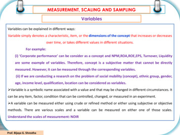
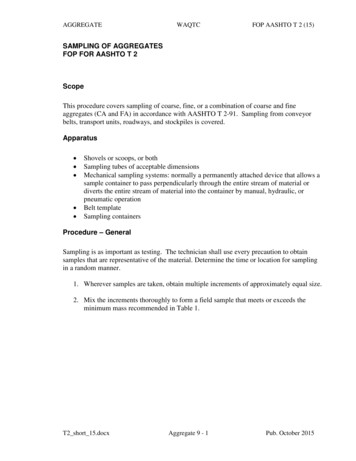
Chapter 7Undisturbed sampling techniquesINTRODUCTIONOf the very large number of sampling techniques devised worldwide since the turn of the century, feware now in current use, and even fewer are in current use in the UK. Here, the most widely used toolsare the 100 mm dia. thick-walled open-drive sampler, the ‘Standard Penetration Test’ 35 mm thickwalled open-drive split barrel sampler, 54mm or 102mm thin-walled fixed-piston samplers, anddouble-tube swivel type core barrels. The types of sampler adopted in each part of the world dependon the state of development of the area, its sampling tradition, economics, and its principal soil types.In the heavily developed South East and Midlands of England, soil types are typically stiff or very stiffclays and weak rocks. In the valleys, alluvium often consists of coarse gravels. Sampling is thereforebased on the use of rugged tools in a large diameter borehole.When carrying out site investigation abroad, the available drilling equipment is often very differentfrom that used at home, and the familiar sampling tools may be either unobtainable or inappropriate.When drilling at home the solution of new problems may require a reappraisal of the value ofcommonly used techniques. These factors require an engineer to be aware of as many types of sampleras possible and this chapter therefore sets out to review the main types of equipment now available.In Chapter 6 (Sampling and sample disturbance) the way in which a number of common types ofsampler are constructed, and the manner in which they work was described. Samples are obtained in anumber of ways:1. by using a number of techniques in shallow pits, shafts and exposures; and2. in boreholes, using either drive or rotary techniques.Drive samplers are pushed into the soil without rotation, displacing the soil as they penetrate. Theygenerally have a sharp cutting edge at their base. In contrast, rotary samplers (often termed‘corebarrels’) have a relatively thick and blunt cutting surface, which has hard inclusions of tungstenor diamond set into it. The sampler is rotated and pushed (relatively) gently downwards, cutting andgrinding the soil away beneath it. A general classification of samplers is shown in Fig. 7.1.Fig. 7.1 General classification of borehole sampling devices.
Undisturbed Sampling TechniquesIt is generally believed that undisturbed sampling is not possible in granular soils. Nonetheless, specialtechniques for sand sampling have been developed over the years, and these are described in a latersection of this chapter. Finally, we consider the selection of appropriate samplers for differentpurposes, and to suit different ground conditions.SAMPLES FROM PITS AND EXPOSURESTrial pits, trenches and shallow excavations are often used in site investigations, particularly duringinvestigations for low- and medium-rise construction, because they provide an economical means ofacquiring a very detailed record of the complex soil conditions which often exist near to the groundsurface. It is worth remembering, however, that trial pits and other exposures can also be used for insitu testing and to obtain high-quality samples.The types of samples taken will vary according to the needs of the investigation. Disturbed samples ofgranular soil are likely to be more representative than those that can be taken from boreholes.Disturbed samples are often taken for moisture content or plasticity determination in the laboratory,and in association with determinations of in situ density. In situ density testing is described in Chapter9.Undisturbed samples can be obtained either by drive sampling (see below) or block sampling (asdescribed in Chapter 6). In either case it is important to recognize the disturbance created byexcavating the trial excavation, and ensure that disturbed material is carefully removed before or aftersampling. To this end, the faces and bottom of the pit should be hand trimmed in the areas to besampled (or described), particularly when the pit has been machine excavated. In exposures, anattempt should be made to remove the weathered surface of the soil.In the UK 38mm open-drive tubes are often hammered into the sides and base of trial pits. These tubesnormally have no check valve, a high area ratio, and no inside clearance. It is often necessary to digthe sample tube out of the soil in order to avoid losses. When U100 tubes (see under ‘Drive samplers’)are used, they require considerable force and are commonly pushed into the soil with a ‘back-actor’bucket. Care must be taken to prevent rocking of sample tubes during driving since this causes seriousdisturbance to the soil at the shoe level. The use of a frame to align the sampler during driving isadvisable.Better quality samples of firm to stiff clay soils can be obtained by trimming the soil in advance of alarge diameter (100—200 mm) sampler. This eliminates the disturbance caused by soil displacementahead of the cutting shoe, but may allow slight lateral expansion of the soil. When the material to besampled is either hard, stoney or coarse and granular, it is essential that advanced trimming of largediameter samples is used.When the soil is sufficiently stiff or cemented to stand up under its own weight, a block sample maybe taken. The normal technique is to cut a column of soil about 300mm cube, so that it will fit inside abox with a clearance of 10—20 mm on all sides. A box with a detachable lid and bottom is used forstorage. With the lid and bottom removed, the sides of the box are slid over the prepared soil block,which is as yet attached to the bottom of the pit. After filling the space between the sides of the boxand block with paraffin wax, and similarly sealing the top of the block, the lid is placed on the box.The block is then cut from the soil using a spade, and the base of the sample trimmed and sealed.Block samples allow complete stress relief, and may therefore lead to expansion of the soil, but in verystiff clays this technique is widely regarded as providing the best available samples (see Fig. 6.5).2
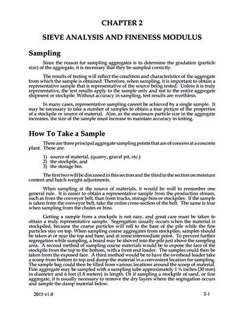
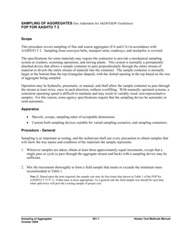
Site InvestigationThe Sherbrooke samplerBlock samples can only be taken from depth in heavily overconsolidated soils, such as the Londonclay. In normally and lightly overconsolidated clays, excavation of a pit or shaft to more than a fewmetres depth is often impossible because base heave will occur. Lefebvre and Poulin (1979) calculatethat, for example, in a clay with an undrained shear strength the depth of a trench or pit will be limitedto about 4 m, if a factor of safety of two is to be maintained.To overcome this problem, Levebvre and Poulin (1979) designed the apparatus shown in Fig. 7.2,which is essentially a down-borehole block sampler. The equipment needs a borehole of about 400mm diameter, which is best cleaned using a flat- bottomed auger, in order to reduce disturbance andminimize the amount of disturbed material left in the base of the hole before sampling. The hole iskept full of bentonite mud. The sampler is lowered to the base of the hole, and rotated, either by handor using a small electric motor, at about 5r.p.m. A cylinder of soil, about 250 mm in diameter, iscarved out by three circumferential blades, spaced at 120 . They make a slot about 50mm wide, andare fed by bentonite or water to help clear the cuttings. The time taken to obtain a sample obviouslydepends upon ground conditions, but may be about 30—40min. After carving out a cylinder about 350mm high, the operator pulls a pin, and the blades (which are spring-mounted) gradually rotate underthe base of the sample, as rotation is continued. Closure of the blades separates the sample from theunderlying soil, and the sample is then lifted to the surface with a block and tackle. Lifting takes placevery slowly for the first 0.5 m, in order to avoid suction at the base of the sample. The sample iscoated with layers of paraffin wax, and may be placed in a container packed with damp sawdust orother suitable material. The complete process takes about 3 h, including preparation for shipment.Tests by Lefebvre and Poulin have shown that this sampler is capable of obtaining soil of comparablequality to that produced by block sampling in the sensitive clays of eastern Canada. The sampler wasused in the Bothkennar clay in Scotland, where it provided the highest quality of samples obtainable(Clayton et al. 1992). It was found, however, that the apparatus is quite time-consuming and difficultto use. Lefebvre and Poulin (1979) note that it is not intended that this technique should replace tubesampling for routine investigations. But where the highest quality samples are required for testing ofsoft or sensitive clays, at the time of writing this apparatus provides the best method of obtainingundisturbed samples from depth.DRIVE SAMPLERSDrive samplers are samplers which are either pushed or driven into the soil without rotation. Thevolume of soil corresponding to the thickness of the sampler wall is displaced into the surroundingsoil, which is either compacted or compressed.Drive samplers can be divided into two broad groups: open-drive samplers and piston drive samplers.Open-drive samplers consist of a tube which is open at its lower end, while piston drive samplers havea movable piston located within the sampler tube. Piston samplers can be pushed through a soft soil tothe desired sampling level, but open-drive samplers will admit soil as soon as they are brought intocontact with, for example, the bottom of a borehole.Open-drive samplersOpen-drive samplers suffer from several disadvantages, as Hvorslev (1949) pointed out. Poor cleaningof the borehole before sampling, or collapse of sides of the borehole after cleaning may mean thatmuch of the recovered soil is not only highly disturbed, but also non-representative. The use of a largearea ratio can induce soil displaced by the sampler drive and causing large-scale remoulding of the3
Undisturbed Sampling Techniquessample. The problems of pressure above the sample during the drive, and of sample retention duringwithdrawal have been noted in the previous chapter.Fig. 7.2 Schematic diagram of the Sherbrooke down-hole block sampler (Lefebvre and Poulin 1979).The advantages of open-drive sampling are principally those of cheapness, ruggedness and simplicityof operation. Open-drive samplers can be arbitrarily divided into two groups. Thin-wall open-drivesamplers have been defined as those with a wall thickness of sampling tube of less than 2.5% of thediameter, corresponding approximately to an area ratio of 10% (Hvorslev 1949). This classification isnot a good guide to the amount of sampling disturbance because of the influence of cutting shoe taperand in situ stress level in the soil. In the following discussion thin-wall sampling devices are taken tobe those with an area ratio of less than 20%, and a suitable cutting shoe taper, while thick-wallsamplers are taken to have an area ratio greater than 20%.4
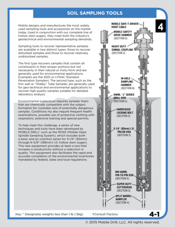
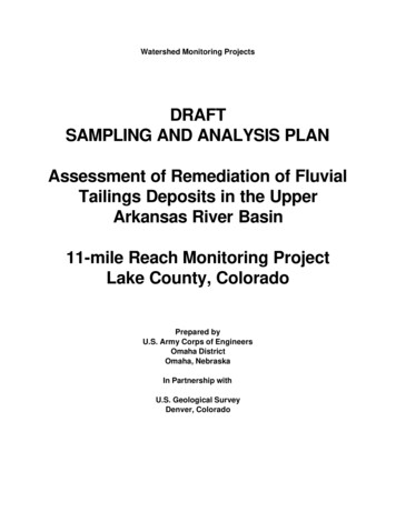
Site InvestigationFig. 7.3 The Sherbrooke sampler in operation (photograph courtesy Dr D.W. Hight).Thick-walled open-drive samplersThick-walled open-drive samplers are widely used throughout the world. In their most common formsthey consist of a solid or split sampler barrel, threaded at both ends to take a cutting shoe (typicallywith inside clearance) and a sampler head provided with either a check valve or vents.BS general purpose samplerThe British Standard General Purpose 100 mm Sampler (BS ‘5930:1981), commonly termed the U100sampler, evolved during the 1930s and 1940s (Le Grand et al. 1934; Cooling and Smith 1936; Cooling1942; Longsdon 1945; Rodin 1949). The sampler is rugged, cheap and will provide a core sample inmost British clays, which are typically heavily overconsolidated. Its size and form were adoptedbecause of the common borehole size at the time of its development, and because of its ability tosample (however ‘inadequately) in stoney very stiff glacial clays.The British Standard U100 sampler will fit inside a 150mm dia. borehole. Harding (1949) noted that:some believe that the smaller the [casing] tube the cheaper will be the hole. This is a fallacy. In Britishgravel-laden deposits, nothing less than 6-inches [152 mm] diameter is worthwhile. This permits theaverage type of stone to be brought up by shell without pounding with a chisel and also allows of 4-inchdiameter sampling.Light percussion drillers will often use 200mm tools in preference to the 150mm size because of theirgreater weight, and thus their improved ability to make fast progress.5
Undisturbed Sampling TechniquesFigure 6.11 shows a typical British 100mm dia. open-drive sampler. It has a 104 mm inside dia. at thebase of the cutting shoe, a 27% area ratio, and an inside clearance of 1.4% provided by tapering theinside diameter of the cutting shoe at an angle of 30 to meet the 106mm internal diameter of thesample tube, or by providing a uniform internal diameter to the cutting shoe and thus stepping out,abruptly at the junction of the shoe and sampler tube. The outside cutting edge taper may be 20 up toa thickness of 2.3 mm, and 7 thereafter, or alternatively may initially be 30 , and then 15 up to a6.5mm thickness. Designs vary according to the manufacturer, but shoes and tubes are alwaysinterchangeable. The normal sample tube length is 457 mm, but two tubes are often coupled togetherin order to allow debris at the bottom of the borehole to pass into the upper tube during driving. Thusthe normal length to diameter ratio is about 4.5, with a possible maximum of 9.The U100 sampler head incorporates vents and a ball valve assembly to allow air or water to leave thetop of the tube as soil enters at its base. The ball valve is also intended to improve the sample retentionby preventing air or water re-entering the top of the tube if the sample starts to slide out. Because ofthe conditions under which the vents and ball valve are expected to work, it is important to ensure thatt
walled open-drive split barrel sampler, 54mm or 102mm thin-walled fixed-piston samplers, and double-tube swivel type core barrels. The types of sampler adopted in each part of the world depend on the state of development of the area, its sampling tradition, economics, and its principal soil types. In the heavily developed South East and Midlands of England, soil types are typically stiff or .