Transcription
TUTORIALDrawing a little mechanicalpart using LibreCADTutorial by Claudio GuarnieriCLAUDIO GUARNIERI: Drawing a little mechanical part using LibreCAD – Page 1 of 17
IntroductionHello everyone! This tutorial is a tutorial for beginners and is made mainly for peoplethat are not into LibreCAD, with the aim to help them to familiarize with it and to havethe opportunity to create immediately something reasonably “productive”. LibreCADhas not yet a real completed manual, this task has taken in charge by a group of bravemen, but you can find some piece of advice into the forum; moreover, even LibreCAD hasbeen totally rebuilt, an idea of its use can be found on Qcad manual. Here I'm using theversion 2 of LibreCAD.This tutorial is also for people that simply need a quick review about the program'scommands. In this little tutorial then, we are going to draw a little part in order to getpeople more into LibreCAD. I suggest to people that have no idea about this programworks, to spend a little time playing with this nice program, I mean, the menus, the lists(block list and library browser), the command line, the sub-menus, and so on. Peopleused to other cads will find easier to understand the icons' logic.Finally I would like to thank Mr. Rallaz of the developers team, that gave me the drawingwe are going to replicate, in fact even if I can use this LibreCAD I'm not in mechanics, so Ineeded something understandable realistic to draw. Thanks Rallaz then!Now we can start our little journey in this drawing.Have fun!ClaudioCLAUDIO GUARNIERI: Drawing a little mechanical part using LibreCAD – Page 2 of 17
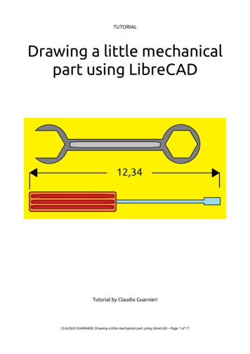
Getting startedWell, we have our program run and we are about to start.First, before set the drawing, the layers and so on, this picture down here represents thedrawing that we are about to create, the final result:First go to Edit Current Drawing Preferences, then set the “paper” section to A4landscape, then on “grid” section select “Orthogonal Grid”. We are not using “splines”but about “units” and “dimensions” look the picture below:CLAUDIO GUARNIERI: Drawing a little mechanical part using LibreCAD – Page 3 of 17
Well, now we can finally set the layers. In order to set layers you need to have the layerlist window active, if you do not see it just click the right mouse button a free space onthe top bar and click with the left mouse button near “layer list” and. Ta daa!!! We havea layer list! Fine, when you have the list the highlited layer is the one you are working in,and if you look down here you can see the relative menu, and preciselyShow all layersLayer proprietiesShow/hide relative layer(in this case layer 0)Remove a layerLock/unlock thenear layerAdd a layerPrint or do not printthe layer objectsHide all layersRemember, the first thing to do, especially in big drawings, is setting the layers, it savestime and sometimes keeps the work readable and understandable.Personally I left to layer 0 its default settings and I gave to the layers the followingsettings as resumed down here:Layer nameColorThicknessLine 8ContinuousAxesRed0,25Dash dot (small)Down here the interface menu to set the layers, naturally each description is to set therelative parameter:And finally we have set the layers!!! Up to now it has not been too difficult, am I right?CLAUDIO GUARNIERI: Drawing a little mechanical part using LibreCAD – Page 4 of 17
SnapsI know I know, you want draw, but this is really important!!! Let me spend some words!Snaps are particular points that you can use as start points to create an object, asreference for dimensioning and so on, they are important because without them wewould entirely type coordinates and coordinates and coordinates and coordinates andcoordinates and coordinates, well you know. In this nice bar we have also horizontal andvertical constraints and the zero positions. Now take a look down here, we have:FreeLock relativezero positionSnap on gridSnap on endpoints,notice that this littlecontour means thatthis snap is selectedSet relativezero positionVerticalconstraintSnap on entityHorizontalconstraintSnap centerSnap middle, this snapcan assign more than amiddle point to a lineSnapintersectionSnap distanceLook down here to have an idea about how much important snaps are, the same try withthe snap grid turned on at the left and turned off at the right!Take familiarity with this bar, it will save much time and will save your er. neck manytimes!CLAUDIO GUARNIERI: Drawing a little mechanical part using LibreCAD – Page 5 of 17
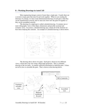
First linesFirst something about coordinates:Orthogonal coordinates: they are coordinates that are identified through an abscissaand an ordinate.Polar coordinates: they are identified through a distance and an angle.Now, no matter if you use orthogonal or polar coordinates, if you simply insertcoordinates, they will be referred to the absolute zero (the red cross into theworkspace), if you type the @ simbol before the coordinates you will insert thecoordinates relatively to the red cursor (the little cirlcle with a cross inside it).Ok friends, now it's time to draw. Each drawing can have a border or can have it not.We are going to put it; the paper is an A4 and we wants 5 units of border, then ourborder will be 287 x 200 units.As you can see LibreCAD has a menu on the left, this will be our closest friend when weare using this program.Now, be sure to operate in layer 0, then click (left mouse button) on the icon “lines” andon the sub-menu “rectangles”. On the command line we will read “Specify first rectanglecorner” and we'll type 0,0. Then to give the second corner we have to insert 287,200 andour border will be set (Remember an A4 is 297 x 210 millimeters)!Now we are going to draw the very part of this tutorial, as you can see it is a crosssection drawing, the section is cutting in two halves this part.The order will be:1. The orthogonal view;2. The isometric view.Part1:We are going to draw first the sectioned part (the part filled with oblique lines). Nowbe sure to operate on the layer SECTIONS, and we can start. Look at the picture: as youcan see there is a cylindrical hole having 25units as diameter and 7,5 height. The squaredpart side is 45 units, then the difference on that area will be 10. The picture down heregives the dimensions of the sectioned part if you keep reasoning in this way:CLAUDIO GUARNIERI: Drawing a little mechanical part using LibreCAD – Page 6 of 17
Now, through the command “line” you can insert all the coordinates. Notice that in thiscase there are command icons called horizontal line and vertical line. If you click on thema dialogue will appear on Tool Options menu (if you do not see it right button click on afree area on the bar and select Tool Option); here you can insert the length of the lines,also the point of attachment, so it will be easier to create the shape in the previouspage. Look down here to have a better idea:Now we have to create the border lines, look at the first picture on page 3, the distancebetween the axes and the cylinders are 12,5 and 8 units. So we need to create lines likedown here (you should not have drawn the axes yet)CAEBDFIn order to draw the axes just switch to layer AXES and draw a line with two points,selecting the A and B points, so the axes will be created from A to B; now we need toextend it: click on Modify Lengthen (actually this command is listed as “Trim byamount”), enter a number on the command line, (keep 10 or 12 as reference ofextension), then click the axes near the top and near the bottom and the magic is done!So far, your situation about the red dash-dotted axe should be exactly like the picture upthere. Now keep considering the picture above, this is the half of the entire picture, andwe have two methods to operate; the first method is switch to BORDERS layer anddrawing the entire left border considering it as a mirror of image at page 5 then join thelines that need to be joined, the second method, more easy, time saving and cool is.CLAUDIO GUARNIERI: Drawing a little mechanical part using LibreCAD – Page 7 of 17
.Modify Mirror!!! So, the description of this second way is longer then the descriptionof the first one, but once you've learned it's really fast. So, switch to BORDERS layer andselect lines CD, DE and EF. Select Modify Mirror and give confirm, when LibreCAD asksthe two points click on the top and the bottom points of the red axes, remember to keepthe original, and les jeux son faits! Now we are at this point, look down1234Now, select the new lines from point 1 to point 4, click on Modify Edit Entity Attributeand give confirm; corresponding to the writing “layer” select BORDERSAnd finally look here: we have the borders!CLAUDIO GUARNIERI: Drawing a little mechanical part using LibreCAD – Page 8 of 17
Well, now it remains to join the lines, so use Modify Extend by amount, or. Well, this isthe very method I always use to join lines, look down friendsHere I selected the segment 1-2 (image at page 8). If you look closely at the endpointsthere are two blue dots, they are important because if I click one of the two endpointsand I keep the left mouse button clicked, the line becomes elastic and I can drag itwherever I want, even to an endpoint snap! So that's the trick! Notice that if I selectmore than entity at once I'll move one point, but two entities will be modified. Lookdown hereAnyway once you'll have learned well, you'll find this feature really helpful as I did!Now the next step is create a hatch on the cut area, so we need to switch to HATCHESlayer, then we have to select all the blue polygon of “section” layer, now click on CreateHatch, give confirm and select on the dialog box the hatch “ansi31” scale 1 and angle 0.Down here I modified the preview in order to avoid doubts, those lines are the hatch!CLAUDIO GUARNIERI: Drawing a little mechanical part using LibreCAD – Page 9 of 17
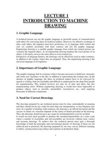
The final step is give dimensions to our work. So just be sure to operate on DIMENSIONSlayer, then click on Dimensions horizontal dimensions Dimensions vertical dimensionsso using the snap bar to set the place to put them. Remember to add the diametersymbol of the 25 and 16 units diameters into the following Tool Option barAs you may have noticed, those two diameters are not yet like they appear in thedrawing at the beginning. Well, it's time to another little trick: first we are going toselect those two dimensions, then we have to click the icon Modify Explode and giveconfirm. Now there are separates entities and we can delete the ones that we don'tneed! Simple isn't it? And the orthogonal art is done!!!!Part2:This part can seem more complex, but is simpler than it seems: in isometric drawingsthere are angles that never change; I mean that we subdivide the space in angles of 120 .Look the arrow in the picture, it indicates how the rotation works. If you still do notunderstand I'll try to answer to your questions with the following image:CLAUDIO GUARNIERI: Drawing a little mechanical part using LibreCAD – Page 10 of 17
Now I am quite sure that you have understood the meaning of that kind of clock and I amalso sure that you understood that we are going to use polar coordinates.I intentionally avoided to skip talking about axes X, Y and Z so far, because LibreCAD is a2D cad, then it would be forcing it to make its own something that does not belong to it,for this reason I did not go far from the angles considerations.Anyway to suppose a hypothetical 3 axes system we would find someting as followingZ90 or 270 X30 or 210 Y150 or 330 So using polar coordinates means that X lines will have angles of 30 or 210 , Y lines willhave angles of 150 or 330 , and Z lines will have angles of 90 or 270 .Well, let's go on then!!!Keeping as reference the drawing on page 3, there we have all the dimensions we needto proceed, we just have to keep in mind that strange clock at page 10.Down here I put the lines' dimensions to give for the isometric part:CLAUDIO GUARNIERI: Drawing a little mechanical part using LibreCAD – Page 11 of 17
Remember the input way: click Lines line with given angle, then insert in Tool Optionsthe numbers! Here in the picture there is an angle of 150 degrees, a length of 10 unitsand the snap point selected is start, this means that in this case you will enter the linefrom the start, but you can also choose to enter it from the end or from the middle.The method is simple, remember that:1. Z axes has always the number and 90 as angle;2. X axes has the number and 30 or 210 ,depending on the snap insertion that youchoose, start or end;3. Y axes has the number and 150 or 330 ,depending on the snap insertion that youchoose;4. The command MIRROR, in this case is exploitableat 100%, once you have done left or right theother side will already be done, just six clicks!Remember also to be sure of being in the proper layer, if you were not, is not necessaryto redraw everything, simply select the entities that need to change layer and go toModify Edit Entity Attributes, then select the correct layer! Ok, if I am not mistakingyou should be in a similar situation, depending if you have done the hatch, if not, do it:This is pretty unrealistic, isn't it? In fact we are going immediately to add the roundborders!As everyone can assume, even if in the reality round parts are circles, we are obviouslygoing to draw ellipses. I have a particular method to draw them and remember that issimpler than it seems!CLAUDIO GUARNIERI: Drawing a little mechanical part using LibreCAD – Page 12 of 17
Our little project has a 45 units sided square at the top, so first of all, switch to a randomlayer that is not BORDERS, because what we are about to draw will be deleted once wewill have created our ellipses. I am operating on layer 0 anyway.Now, we have to consider that a circle is always inscribed in a square, and its diameter isthe half part of the square side, if I have not been clear enough just look down hereOur drawing has 5 circles that creates cylinders of the piece. Looking at the orthogonalpart (Part1) and starting from the top their diameters are: 25 units; 25 units (external circle); 16 units (internal circle); 16 units (internal circle); 40 units (external circle).So we are going to draw five squares in the isometric view.The first square is 25units sided, so let's create its axes on the isometric piece; thoseaxes will be useful for the other ellipses too! Anyway look here:X axesY axesI just turned offHATCHES layerI just turned offHATCHES layerCLAUDIO GUARNIERI: Drawing a little mechanical part using LibreCAD – Page 13 of 17
Fine, now go in a free area, and create a 25units sided square in isometric view, just usethe polar coordinates and X-Y angles, then create a horizontal line from left to rightvertex. Here the result (naturally I have just put dimensions to show):Next, using the command Modify Move/Copy move this figure using as first point thehorizontal line middle point and as final point the intersection of the two axes that wehave drawn int the previous page. We can delete the horizontal line. The result is like thepicture below, except for the horizontal line that I left for a better understanding:Now we have to create the foci! To do that we need to join the high vertex of the squareto the middle point of the opposite sides and join the low vertex of the square to themiddle point of the opposite sides, and here we are:DCBHGEFACLAUDIO GUARNIERI: Drawing a little mechanical part using LibreCAD – Page 14 of 17
Finally we can switch to layer BORDERS, and it's time to create our ellipse through thecommand. Arcs! Yep, you have read well! So click on Arcs Arc with Center PointsAngles. Then select A as center, then select segment AC as radius, finally, D as start pointand C as final point and. voilà!!!Using the same w ay center in D, radius is DE, the startpoint is E and final point is F! Eureka!!! We have create an ellipse! Look down here:abQThe next thing to do is delete the square and that we don't need anymore, delete also“a” and “b” lines. Next create a 7,5 units vertical line from point Q towards the bottom,7,5 units because this is the measure in the drawing, look the dimensions at page three!This is the segment QK. Creating the second ellipse is really easy, just use the commandModify Move/Copy and give Q as first point and K as final point. Ta daaa!!!QKI turned off AXESlayer to make morereadable this imageThen, (I switched back to layer 0) create another square 16 units sided in a free space,create axes and ellipse construction lines, then move it from its geometrical center to K.Here the result:CLAUDIO GUARNIERI: Drawing a little mechanical part using LibreCAD – Page 15 of 17
Now you should know what to do, switch to layer BORDERS and create the ellipse withthe appropriate centers and radiuses. Next create a vertical line of 45 units from K pointtowards the bottom (dimension taken from drawing on page 3).Finally select this last ellipse and using the command Modify Move/Copy, copy it using Kas first point and L as endpoint.QKLFinally create a 40 sidedsquare, axes, diagonals and so on, move this figure from its center to L point and createthe last ellipse. Then delete QK and KL segments. The final picture will be this one.UTRemaining in BORDERS layer, create vertical lines from points U and T towards thesquare borders to complete the picture. Now you can delete the square!And yo will have just to delete the ellipses parts that are exceeding. To to this go toModify Divide and choose first the entities to be cut, then where to cut (use snaps!)CLAUDIO GUARNIERI: Drawing a little mechanical part using LibreCAD – Page 16 of 17
And you will have drawn the entire part, orthogonal view and isometric view!!! That's all!ConclusionsWell, I hope that you found this tutorial interesting, I am pretty sure that you may havefound too long some parts and too short some others, I hope anyway that you havetaken more familiarity with this useful program. There are a lot of features that herehave not been even considered, but just be curious, that's the secret! I would like tothank carbonardo and LordOfBikes of the forum about the Lengthen command, that wasnot explained properly in the previous version of this PDF. I thank you too for readingand.See ya!ClaudioCLAUDIO GUARNIERI: Drawing a little mechanical part using LibreCAD – Page 17 of 17
This tutorial is also for people that simply need a quick review about the program's commands. In this little tutorial then, we are going to draw a little part in order to get . drawing the entire left border considering it as a mirror of image at page 5 then join the lines that need to be