Transcription
Tuesday, 23 March 2004Groundwater monitoringGuidelines and review58.558Reduced level mAHD 3Jan-92Jan-91Jan-90Jan-8955Peter Dahlhaus, Briony Muller, Mark Dixon, Warren Feltham, Narelle Beattie and Bob Smith.Geology Department, University of Ballarat
Corangamite CMA. Groundwater monitoring guidelines and reviewExecutive SummaryThis groundwater monitoring guidelines and review research project was initiated by theCorangamite Catchment Management Authority (CCMA) and funded by the NationalAction Plan for salinity and water quality. The fundamental goal of the project is to providethe best possible basis for monitoring the targets required by the NAP, in particular,groundwater levels, salinity risk and salinity loads. The general output from this researchcontributes to the regional knowledge base and benchmark register, and provides input tothe Corangamite Salinity Action Plan and the Corangamite Regional Catchment Strategy.The project follows from the construction of a Corangamite Groundwater Monitoring andResearch Database (CGMRD) in 2003. The 9260 bores in the CGMRD are combinedfrom three State government databases and include 956 bores in the CCMA region with amonitoring record. The number of monitoring records for the individual bores varies fromone record to 305 records, with the majority of monitored bores containing between 50and 100 records. The spatial distribution of the monitoring bores is shows highernumbers clumped in areas where groundwater monitoring is, and has been, required.These include the salinity ‘Hot Spots’ of the former CCMA salinity management plan andthe areas of groundwater extraction.A review of Restoring the Balance (Nicholson, 2002) indicated that 580 salinity monitoringbores had been constructed in the first decade of salinity management in theCorangamite CMA region, although only 519 were listed in the database. Of these, a fieldchecking program located 409 bores, with the remaining 110 consisting of 42 bores thatcould not be located with the information available, 62 that apparently did not exist at all inthe area of their stated location (based on landholder information), and 6 that werelocated but their identity could not be determined. All field checked bores were accuratelylocated using Global Positioning System (GPS) technology, photographed, measured fordepth, water level and salinity, and their condition reported. Of the 409 bores, 75 (19%)had broken standpipes, with 52 (13%) broken at or below ground level and 23 (6%)broken above ground level. The field checking measured 266 bores shallower thanrecorded (most possibly due to silting) and 81 bores deeper than recorded.Several modifications have been made to the operation of the CGMRD to overcomesome of the shortcomings recognised in this project. The database has been partlycleaned by the removal of 226 clearly identified duplicates in the monitoring bores listed.Improved functions such as links to photographs and maps to assist in the recognition ofa bore and its location have been added.For the salinity bores in the CCMA region, the limitations in the quality of the monitoringrecord results in ambiguity and uncertainty in the interpretation of the results. Thisuncertainty compromises the ability to properly audit the targets for catchment conditionset by the RCS, and quantify the benefits of NAP investment.The recommendations of this project fall into three main categories: the continuousimprovement of the CGMRD; changes to the current groundwater monitoring; andrequirements for new monitoring bores. Additional monitoring bores are required in targetareas where bores do not currently exist. Preference should be given to bores required toset the resource condition targets in the salinity target areas. Initially the Geelong – LakeConnewarre area stands out, as there are no groundwater monitoring bores currentlylisted. Other areas which urgently require more monitoring bores are the Morrisons –Sheoaks, Lara and Illabarook target areas.University of Ballarat. Geology department.i
Corangamite CMA. Groundwater monitoring guidelines and reviewTable of Contents1INTRODUCTION . 11.11.21.32BACKGROUND AND CONTEXT OF THE RESEARCHAIMS OF PROJECTPROJECT STRUCTURE122GROUNDWATER MONITORING . 32.12.22.32.43OBSERVATION BORES AND PIEZOMETERSINTERPRETATION OF WATER LEVELSMEASURING GROUNDWATER SALINITYGROUNDWATER MONITORING PROTOCOLS3556REVIEW OF CORANGAMITE GROUNDWATER DATABASE. 73.13.23.34HISTORY OF GROUNDWATER DATA COLLECTION IN VICTORIAASSEMBLY OF THE CGMRDREVIEW OF THE CGMRD FUNCTIONALITY AND USEFULNESS788FIELD CHECKING OF SALINITY BORES. 104.14.24.35METHODSRESULTSLANDHOLDER COMMENTS101217REVIEW OF MONITORING RECORD . 185.15.25.36NUMBER OF MONITORED BORES AND RECORDSSPATIAL DISTRIBUTIONQUALITY OF MONITORING RECORD181923DATABASE MODIFICATION. 266.16.26.36.47DATA CLEANINGDATA UPDATES AND ADDITIONSMISSING AND BAD DATACHANGES TO DATABASE OPERATION26272828GROUNDWATER MONITORING NEEDS IN THE CCMA. 297.17.27.37.47.58PURPOSEPARAMETERSLOCATIONTYPE OF MONITORING BOREBORE MONITORS2930303434SUMMARY OF RECOMMENDATIONS . 358.18.28.3CONTINUOUS IMPROVEMENT OF THE CGMRDCURRENT MONITORING NETWORKENHANCEMENTS TO THE MONITORING NETWORKUniversity of Ballarat. Geology department.353536ii
Corangamite CMA. Groundwater monitoring guidelines and reviewList of FiguresFigure 2.1 Observation bore and piezometer constructionFigure 2.2 Piezometer nests used to determine recharge and dischargeFigure 2.3 Incorrect interpretation of waterlevels.Figure 3.1 Sources for CGMRD (data from Nolan-ITU, 2003a)Figure 3.2 Examples of bore photographsFigure 3.3 Bore location statisticsFigure 3.4 Exemplary bore location practiceFigure 3.5 Condition of bore standpipesFigure 3.6 Condition of bore capsFigure 3.7 Varying states of bore condition due to guardingFigure 3.8 Discrepancy between measured depth of bores and recorded total depth.Figure 3.9 Measured salinity of bore watersFigure 3.10 Geological units in which salinity monitoring bores have been constructedFigure 3.11 Landscape position in which salinity monitoring bores have been constructedFigure 5.1 Number of monitored bores and monitoring recordsFigure 5.2 Distribution of monitoring bores in the CCMA regionFigure 5.3 Number of monitoring bores by GFSFigure 5.4 Distribution of monitoring bores by groundwater protection areaFigure 5.5 Distribution of monitoring bores by SAP target areaFigure 5.6 Monitoring record for Bore 64227.Figure 5.7 Hydrographs of four bores at PittongFigure 5.8 Hydrograph response of 3 bores in the HeytesburyFigure 6.1 An example of changes made to the database (Lismore district).Figure 7.1 Priority areas for monitoring bore locationFigure 7.2 Examples of groundwater - landscape 425263233List of TablesTable 5.1Table 5.2Table 5.3Table 5.4Bores with more than 200 monitoring records.Monitoring bores listed in each GFSMonitoring bores listed in groundwater protection areasNumber and percentage of monitoring bores by SAP target area18202122List of AppendicesAppendix AAppendix BAppendix CAppendix DAppendix EAppendix FAppendix GResearch team and Steering CommitteeBore monitoring protocolsDetailed comments on functionality of the CGMRDExample field sheet and details of field equipmentDuplicated Bores removed from CGMRDFull listing of monitored boresBore decommissioning notesUniversity of Ballarat. Geology department.39405457596472iii
Corangamite CMA. Groundwater monitoring guidelines and reviewList of PAMeaningCorangamite Catchment Management AuthorityCorangamite Groundwater Monitoring and Research DatabaseCentre for Land Protection ResearchDepartment of Primary IndustriesDepartment of Sustainability and EnvironmentElectrical Conductivity (usually measured in µS/cm)Geological Exploration and Development Information SystemGroundwater flow systemsGroundwater Management AreaGeological Survey of VictoriaNational Action Plan for salinity and water qualityPermissible Annual VolumeRegional Catchment StrategyRural Water Commission, later the Rural Water CorporationSalinity Action PlanSoil Conservation AuthoritySinclair Knight Merz Pty LtdState Observation BoresSouthern Rural WaterState Rivers and Water Supply CommissionTotal Dissolved Salts (usually measured in mg/l or ppm)Victorian Groundwater Data BaseVictorian Volcanic PlainsWater and Land Use Change projectWater Supply Protection AreaUniversity of Ballarat. Geology department.iv
Corangamite CMA. Groundwater monitoring guidelines and review1IntroductionThis groundwater monitoring guidelines and review research project was initiated by theCorangamite Catchment Management Authority (CCMA) and funded by the NationalAction Plan (NAP) for salinity and water quality. The fundamental goal of the project is toprovide the best possible basis for monitoring the targets required by the NAP, inparticular, groundwater levels, salinity risk and salinity loads. The general output from thisresearch contributes to the regional knowledge base and benchmark register, andprovides input to the Corangamite Salinity Action Plan (SAP) (Nicholson et al., 2003) andthe Regional Catchment Strategy (RCS) (CCMA, 2003).1.1 Background and context of the researchThe initial Corangamite dryland salinity management plan – Restoring the Balance - waslaunched in December 1992 (Nicholson et al., 1992). The plan was implemented by theCorangamite Salinity Forum, which later evolved into the Corangamite SalinityImplementation Group and finally the Corangamite Catchment Management Authority in1997. Among the many achievements in the implementation of Restoring the Balancewas the establishment of an extensive monitoring network that included 580 bores and 14surface water monitoring stations (Nicholson, 2002).The monitoring of waterlevels in the salinity bores has been reported to the CCMA (andprecursors) on an intermittent basis (eg. Heislers, 1995, Pillai & Heislers, 2000). Theresults have been subjected to basic trend analysis to determine if the groundwater levelsare rising or falling and if the associated salinity treatments have been successful. Withinthe CCMA this analysis of groundwater trends is critical to monitoring the SAP resourcecondition targets, and auditing the goals of both the RCS and the NAP. Ideally the salinityplan implementation committee would use the results of the monitoring and evaluation toguide their decisions on investing in salinity management.However, of the salinity bores currently reported to the CCMA, approximately one thirdhave been constructed to monitor the effectiveness of particular salinity treatments. Insome situations, the monitored groundwater levels do not have an unequivocal provenrelationship to the treatment adopted. Local groundwater systems are often assumedand monitoring bores are placed in the area where trees have been planted, even thoughthe simplistic relationship between cause and effect is based on little direct evidence. Ifthe salinity at a specific site is related to a regional or intermediate groundwater flowsystem, the water levels and salinity values recorded at that site will have little or norelationship to the salinity management investment at that site. In these circumstances,groundwater levels may be rising and the area affected by salinity increasing, eventhough recharge control planting has been undertaken, whereas discharge control maybe more effective.A review of Restoring the Balance (Nicholson, 2002) and the development of the secondgeneration Corangamite SAP (Nicholson, et al., 2003) identified the need for a review ofthe CCMA groundwater monitoring program and the development of a comprehensiveCCMA groundwater monitoring database. The construction of the CorangamiteGroundwater Monitoring and Research Database (CGMRD) was completed in August2002 (Nolan-ITU, 2003c). This project completes the review of the monitoring networkand establishes guidelines for future monitoring.University of Ballarat. Geology department.1
Corangamite CMA. Groundwater monitoring guidelines and review1.1.1OpportunitiesIn addition to the salinity monitoring bores, there are approximately 460 groundwatermonitoring bores that have been constructed by various the government agenciesresponsible for the management of groundwater since the introduction of theGroundwater Act in 1969. Although many of these State Observation Bores (SOB) areregularly monitored for groundwater management, the results are not reported to theCCMA or evaluated for the implementation of the salinity management plan.The monitoring of groundwater bores within the CCMA region has varied according to theprotocols and needs of the responsible authority. The Department of Sustainability andEnvironment (DSE), the Department of Primary Industries (DPI), the CCMA and allprecursors to these authorities have been responsible at various times for the installation,monitoring and maintenance of the groundwater bore monitoring network. At present theDSE has a program to combine the various groundwater databases and rationalise theState monitoring needs (Minchin, pers. comm.).However the needs of the CCMA vary from those of the State. The CCMA requires acomprehensive groundwater monitoring network to evaluate the resource conditiontargets in the SAP, as well as monitor regional trends. This could be partly achieved byassessing the suitability of the currently monitored bores (regardless of their origins) toprovide the required parameters and quality of groundwater data. Where insufficient dataof suitable quality is available, an assessment can be made to upgrade existing bores orconstruct new bores. Similarly, where current monitoring is not required, bores may bedecommissioned from the network.1.2 Aims of projectThe project aims to:1. Review the recommendations from Stage 1 and provide the CCMA with a platform fordata rectification.2. Review the monitoring needs and network to relate the data to the needs of theCCMA, specifically in relation to SAP targets, RCS and NAP auditing.3. Establish common guidelines for data collection, database entry and reporting of themonitoring data.4. Establish guidelines for the responsible use of the monitoring data within a frameworkof confidence limits. Higher confidence is given to proven groundwater systems,lower confidence to conceptual groundwater systems.5. Educate the community to the need and importance of monitoring and encourageparticipation in the process.6. Develop a tool to geo-spatially determine the most appropriate locations for boreplacement.7. Identify knowledge gaps in the monitoring network and make recommendations toaddress the shortcomings.1.3 Project structureThe project has been undertaken by a research team within the Geology department inthe School of Science and Engineering at the University of Ballarat, Mount Helen. Theresearch team was guided by a steering committee comprising key stakeholders ingroundwater monitoring in the region. Details of both groups are appended (Appendix A).University of Ballarat. Geology department.2
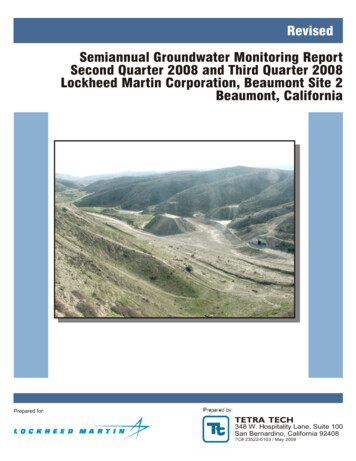
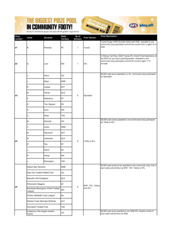
Corangamite CMA. Groundwater monitoring guidelines and review2Groundwater monitoringThe monitoring of groundwater by the CCMA is required to assess the management ofthe catchment resource condition, as stated in the RCS and sub-strategies and plans. Inparticular, the SAP lists resource condition targets which require no net gain in the area ofsecondary saline discharge, no net loss in the areas of primary saline discharge and theestablishment of targets for groundwater dependent ecosystems and other environmentalsites (including refugia). These targets require the monitoring of groundwater levels andsalinity (among other parameters).2.1 Observation bores and piezometersAs the majority of groundwater is not able to be observed, bores and piezometers aretraditionally used for monitoring. Observation bores and piezometers differ in theirconstruction details and are used to measure different things (Figure 2.1).An observation bore can be constructed in a variety of different ways, but essentiallymeasures the rise and fall of the watertable. The watertable, or phreatic surface, is thetop of the saturated zone where the fluid pressure in the pore spaces of the soil or rock isequal to atmospheric pressure. An observation bore typically comprises a hole drilled tothe desired depth and cased with a solid pipe (PVC or steel) to a distance below thewatertable. In fractured rock, the bore may be left open (uncased) beyond this point. Ifthe material surrounding the bore is sandy or subject to collapse, a slotted pipe or woundwire screen is used to keep the borehole open and allow water to enter the borestandpipe. The water rises up the bore to the level of the watertable at that location.A piezometer is constructed to measure the total hydraulic head of water at a particularpoint in the groundwater system. The total head, being the sum of the elevation head andpressure head, may be higher or lower than the watertable, depending on the fluid energyat that point in the system. Piezometers are available in many forms:1. An open or standpipe piezometer is used when the permeability of the rock or soil isusually greater than one mm/day. These are typically constructed by using a shortlength of slotted screen, usually wrapped in a filter cloth and surrounded by poroussand or gravel, which is isolated at a particular depth in the system by sealing the holeabove with an impermeable clay plug (Figure 2.1).2. A Casagrande piezometer is very similar to the above, but has a perforated tipattached to a smaller diameter pipe. Where the permeability of the ground is lessthan one mm/day, the time lag in the response of an open piezometer can be toogreat and a Casagrande piezometer is used. The porous tip (usually 60 µm porediameter or less) and small diameter pipe improve the response time betweenchanges in the water pressure and the level of water in the standpipe.3. Where the permeability of the rock or soil is below about 10 µm/day, the time lag ofopen or Casagrande piezometers becomes too great for some monitoringapplications. For example, approximately 5 days would be required for a typical openpiezometer to reach equilibrium after a change in groundwater pressure in a rock orsoil having a permeability of 1 µm/day. In monitoring applications where the changein pressure is critical (eg. dam walls, landslides, tunnels and mines) more responsiveinstruments are required. These include pneumatic piezometers, vibrating wirepiezometers and vibrating strip piezometers.University of Ballarat. Geology department.3
Corangamite CMA. Groundwater monitoring guidelines and reviewBore capStandpipeConcrete collarPiezometric levelGroundwater levelCement groutBentonite sealSand or gravelSlotted screenSumpEnd capObservation boreStandpipe PiezometerFigure 2.1 Observation bore and piezometer constructionThe total head measured by piezometers constructed at various depths in the samespatial location (termed a piezometer nest) provides information on the direction ofgroundwater flow (Figure 2.2). Like any fluid, water flows from higher to lower pressure,and piezometer nests can be used to determine if water is flowing into (recharge) or out of(discharge) a system.Ground surfaceWatertableDeepest piezometerhas lowest head,indicating rechargeGroundwater flowDeepest piezometerhas highest head,indicating dischargeFigure 2.2 Piezometer nests used to determine recharge and dischargeUniversity of Ballarat. Geology department.4
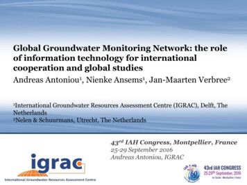
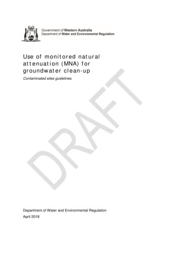
Corangamite CMA. Groundwater monitoring guidelines and review2.2 Interpretation of water levelsGiven that observation bores and piezometers can provide different information on thesame flow system, knowledge of the bore construction details is obviously essential forthe correct interpretation of the groundwater surface. More importantly, the constructiondetails need to be associated with the record of materials encountered at depth duringdrilling the bore (lithological log). Bores of different depth in a regional location may not bemonitoring the same groundwater flow system, depending on the subsurface conditionsand the bore construction (Figure 2.3).Incorrect interpretationof watertable (or head)Potentiometric headof lower aquiferWater table ofupper aquiferBore screenedin upper aquiferUpper aquiferConfining layerBore screenedin lower aquiferBore screenedacross bothaquifersLower aquiferBore screenedin lower aquiferFigure 2.3 Incorrect interpretation of waterlevels.(source: modified from Leonard, 2003)Similarly, any groundwater flow system that leads to total head values in an aquifer thatexceed the surface elevation will produce artesian bores. Therefore, artesian bores andsub-artesian bores can be either geologically controlled (as shown in Figure 2.3 above) ortopographically controlled (as shown in Figure 2.2 on previous page). The correctinterpretation requires knowledge of the geometry of the groundwater flow system in threedimensions.2.3 Measuring groundwater salinitySalinity is a measure of the Total Dissolved Salts (TDS) in water. Since salts in solutiondissociate into ions, the ability of the solution to conduct an electrical current isproportional to the TDS of the solution. Therefore Electrical Conductivity (EC) iscommonly measured as a surrogate for salinity measurement. In Système International(SI) units, EC is reported in siemens per metre (S/m), however decisiemens per metre,millisiemens per centimetre or microsiemens per centimetre are more commonly used inpractice (1 dS/m 1 mS/cm 1000 µS/cm). The conversion of EC readings (µS/cm) toTDS (mg/l) requires multiplying by a factor between 0.55 and 0.75 depending on the ioniccomposition of the solution.Sampling groundwater from a bore usually requires purging a minimum of three times thevolume of water held in the bore to ensure that the water sampled is direct from theaquifer. Water standing in the bore casing for a length period may have changed insalinity due to precipitation of salts, or changes in water chemistry associated with theoxygenation of the water.University of Ballarat. Geology department.5
Corangamite CMA. Groundwater monitoring guidelines and review2.4 Groundwater monitoring protocolsMeasuring groundwater levels and sampling groundwater for analyses is usuallyconducted according to a standard, so that the quality of the data is assured and theresults are comparable.The most basic method of measuring a groundwater level in a bore uses a whistle(usually a ‘fox whistle’) fitted to the upper end of a tube which is attached to a tapemeasure. As the tube is lowered down the bore, the lower end enters the standing waterand the air compressed in the tube makes the whistle work. The distance from thestanding water level to the top of the bore is then measured by the tape. An alternativeand more reliable method uses a weighted probe with electrical contacts that complete acircuit when they come into contact with the water surface. The closed circuit isconnected to a battery which is used to create a sound speaker and/or light to operate,and the distance is measured on the graduated electrical cable. The most sophisticatedmethods use capacitance probes which are permanently installed in the bore below thewatertable and supply a continuous readout of the varying depth of the column of water inthe bore.Sampling water quality is much more difficult as the chemistry of the water can changeaccording to the sampling method and treatment of the sample. Standards forgroundwater sampling are provided by Australian and International standards and EPAVictoria. The two most important are: AS/NZS 5667.11:1998 Water Quality Sampling – Guidance on sampling of groundwatersAS/NZS 5667.1:1998 Water Quality – Sampling – Guidance on the design of samplingprograms, sampling techniques and the preservation and handling of samples.Guidelines for measuring groundwater levels and salinity for the Victoria salinitymanagement programs were developed by the DPI, and are included as Appendix B.Although not as rigorous as international standards, these monitoring protocols are suitedto their purpose and designed for community use.In the USA, approximately 40 groundwater standards have been developed by theAmerican Society for Testing and Materials (ASTM), partly driven by the increasing needfor accountability in a litigious society. These include every aspect of the installation,maintenance and rehabilitation of monitoring wells through to the choice of samplingequipment and treatment of samples and the modelling of groundwater flow systems.Relevant examples include: ASTM D6000-96 (2002) Standard guide for presentation of water-level Information fromground-water sites.ASTM D6089-97 (2003) Standard guide for documenting a ground-water sampling event.ASTM D4448-01 Standard guide for sampling ground-water monitoring wells.The CCMA is also increasingly accountable for the reporting of catchment condition underthe RCS. The investment of public funds is in part dependent on the progress towardsmeeting the targets for catchment condition set by the RCS. Auditing the progresstowards reaching the targets relies on the appropriate and correct monitoring data, andthe implementation of strict protocols is required to ensure that the data is of the highestquality.University of Ballarat. Geology department.6
Corangamite CMA. Groundwater monitoring guidelines and review3Review of Corangamite groundwater databaseA comprehensive groundwater bore database was assembled for the Corangamite regionin 2002 (Nolan-ITU, 2003b). The CGMRD is intended as the dynamic repository ofgroundwater monitoring data for the region, available and accessible to the Corangamitecommunity and stakeholders. Ideally, the database should provide relevant information,including up-to-date waterlevel readings, for any of the monitored bores.3.1 History of groundwater data collection in VictoriaThe first comprehensive groundwater bore database was assembled by the GeologicalSurvey of Victoria (GSV) in the late 1960s, with the introduction of the Groundwater Act1969. A digital database, compiled from the existing records of Government bores (fromthe commencement of the GSV in 1852) and the few records of private bores, wasprogressively assembled on mainframe computers. Historically, the bores were identifiedby Parish and bore number. In each Parish, the Government bores were assignedsequential numbers from 1 to 8000, records of private bores before the introduction of theGroundwater Act 1969 were assigned 8000 – 10000, and private bore records after theAct were sequentially numbered 10000 onwards. Following the introduction of the WaterAct 1988, the private bores in each Parish were sequentially numbered from 15000.From 1969, the legislation required a permit to drill groundwater bores, and theinformation captured by the registration process was added to the database. Thisincluded groundwater investigation or observation bores drilled by other governmentagencies such as the State Rivers and Water Supply Commission (SRWSC) and the SoilConservation Authority (SCA) and subsequent equivalents, although these agencies alsokept a bore database.Following the split of the groundwater group from the GSV in mid 1988 the bore databasewas duplicated. One copy was merged with several Rural Water Corporation (RWC)databases to become the Victorian Groundwater Data Base (VGDB), and the other copywas developed into the Geological Exploration and Development Information System(GEDIS), which included the mineral exploration bores. Data exchange was attemptedfor a few years following the split, but ultimately the databases grew into quite separateentities. Both bore databases converted to using a unique bore identifier rather than thehistorical Parish system.The SCA began to investigate salinity in the late 1970s and developed separatedatabases for salinity monitoring. Since the release of the first Victorian Salinity Strategyin 1988, the salinity bore database has emerged as the Centre for Land ProtectionResearch (CLPR) database, first compiled in 1994 (M. Reid, pers comm.).The current situation is complex. The VGDB is administered by DSE but the datamanagement and monitoring are outsourced to private consultants. The GEDISdatabase is administered and managed by the GSV, within DPI. The CLPR database isadministered by Primary Industries Research Victoria (PIRVic) within DPI and themonitoring is partly outsourced to the community and partly conducted by the DPI, bothPIRVic and the locally-based extension officers.Several other bore databases were developed by public utility agencies that have nowbeen privatised. Although most groundwater data has probably been captured on theVGDB, a vast amount of geotechnical and lithological information has been archived.Similarly a great deal of information stored in independent databases maintained byresearch organisations and consulting companies is not accessible in the public domain.University of Ballarat. Geology department.7
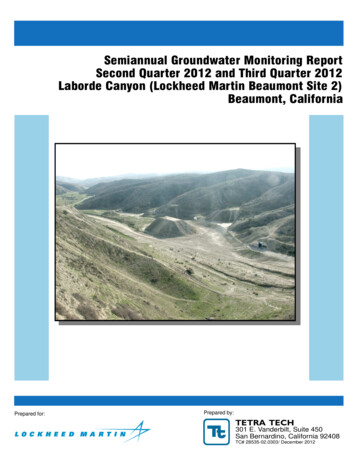
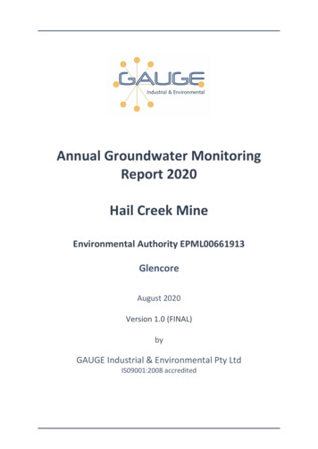
Corangamite CMA. Groundwater monitoring guidelines and review3.2 Assembly of the CGMRDThe 9260 bores in the CGMRD are combined from 8058 VGDB bores, 677 GEDIS boresand 519 CLPR bores (Figure 1).CGMRD 9260 bores4735 GEDIS /VGDB bores8058 VGDB bores17 VGDB /CLPR bores677 GEDIS bores519 CLPR boresFigure 3.1 Sources for CGMRD (
Corangamite CMA. Groundwater monitoring guidelines and review University of Ballarat. Geology department. 1 1 Introduction This groundwater monitoring guidelines and review research project was initiated by the Corangamite Catchment Management Authority (CCMA) and funded by the National Action Plan (NAP) for salinity and water quality.