Transcription
RevisedSemiannual Groundwater Monitoring ReportSecond Quarter 2008 and Third Quarter 2008Lockheed Martin Corporation, Beaumont Site 2Beaumont, CaliforniaPrepared for:Prepared by:TETRA TECH348 W. Hospitality Lane, Suite 100San Bernardino, California 92408TC# 23522-0103 / May 2009
TETRA TECH, INC.MARCH 2009TABLE OF CONTENTS1.0INTRODUCTION .1-11.1SITE BACKGROUND.1-12.0SUMMARY OF MONITORING ACTIVITIES .2-12.1GROUNDWATER LEVEL MEASUREMENTS .2-12.2GROUNDWATER SAMPLING.2-12.3SURFACE WATER SAMPLING.2-82.4ANALYTICAL DATA QA/QC .2-82.5HABITAT CONSERVATION.2-83.0GROUNDWATER MONITORING RESULTS .3-13.1GROUNDWATER ELEVATION.3-13.2GROUNDWATER FLOW.3-13.3GROUNDWATER GRADIENTS.3-93.4ANALYTICAL DATA SUMMARY .3-113.4.1 Data Quality Review.3-113.5CHEMICALS OF POTENTIAL CONCERN .3-163.5.1 Organic Analytes .3-193.5.2 Organic COPCs .3-223.5.3 Inorganic Analytes.3-223.5.4 Inorganic COPCs .3-243.6SURFACE WATER SAMPLING RESULTS.3-243.7GENERAL MINERAL SAMPLING .3-243.8TEMPORAL TRENDS IN GROUNDWATER CHEMICALCONCENTRATIONS .3-303.9HABITAT CONSERVATION.3-354.0SUMMARY AND CONCLUSIONS .4-14.1GROUNDWATER ELEVATION AND FLOW.4-14.1.1 Groundwater Gradients.4-14.2WATER QUALITY MONITORING.4-24.3GROUNDWATER MONITORING PROGRAM AND THE GROUNDWATERQUALITY MONITORING NETWORK .4-55.0REFERENCES .5-16.0ACRONYMS AND ABBREVIATIONS .6-1Semiannual Groundwater Monitoring ReportSecond Quarter 2008 and Third Quarter 2008Beaumont Site 2i
TETRA TECH, INC.MARCH 2009LIST OF FIGURESFigure 1-1 Regional Location Map of Beaumont Site 2 .1-3Figure1-2 Historical Operational Areas and Site Features .1-5Figure 2-1 Site Map .2-3Figure 2-2 Second Quarter 2008 Sample Locations .2-6Figure 2-3 Third Quarter 2008 Sample Locations .2-7Figure 2-4 Surface Water Sampling Locations.2-9Figure 3-1 Second Quarter 2008 Changes in Groundwater Elevations .3-3Figure 3-2 Third Quarter 2008 Changes in Groundwater Elevations .3-4Figure 3-3 Second Quarter 2008 Groundwater Contours for First Groundwater .3-5Figure 3-4 Second Quarter 2008 Groundwater Contours for San Timoteo Formation.3-6Figure 3-5 Third Quarter 2008 Groundwater Contours for First Groundwater .3-7Figure 3-6 Third Quarter 2008 Groundwater Contours for San Timoteo Formation .3-8Figure 3-7 Trichloroethene Isoconcentration Map .3-21Figure 3-8 Perchlorate Isoconcentration Map.3-23Figure 3-9 General Mineral Sampling Locations – Second Quarter (June) 2008.3-26Figure 3-10 Siff Diagrams .3-29Figure 3-11 Perchlorate and TCE Statistical Analysis Summary Results .3-34LIST OF TABLESTable 2-1 Sampling Schedule and Analysis Method - Second Quarter 2008.2-4Table 2-2 Sampling Schedule and Analysis Method - Third Quarter 2008.2-5Table 3-1 Groundwater Elevation Data - Second Quarter 2008 and Third Quarter 2008 .3-2Table 3-2 Summary of Horizontal and Vertical Groundwater Gradient.3-10Table 3-3 Summary of Detected Validated Organic Analytes - Second Quarter 2008 Quarter2008 .3-13Table 3-4 Summary of Detected Validated Organic Analytes - Third Quarter 2008 Quarter 2008 .3-14Table 3-5 Summary of Detected Validated Inorganic Analytes – Second Quarter 2008 and ThirdQuarter 2008 .3-15Table 3-6 Summary Statistics of Validated Organic and Inorganic Analytes Detected SecondQuarter 2008 .3-17Table 3-7 Summary Statistics of Validated Organic and Inorganic Analytes Detected ThirdQuarter 2008 .3-18Table 3-8 Summary of Validated General Minerals Results - Third Quarter 2008 .3-27Table 3-9 Summary of General Minerals Reported in Milliequivalents - Third Quarter 2008 .3-27Table 3-10 Summary of Mann-Kendall and Linear Regression Statistical Analysis.3-33Table 4-1 Historic Maximum and Minimum COPC Concentrations .4-4Table 4-2 Well Classification and Sampling Frequency.4-6Table 4-3 Monitoring Well Sampling Schedule and Frequency.4-8Semiannual Groundwater Monitoring ReportSecond Quarter 2008 and Third Quarter 2008Beaumont Site 2ii
TETRA TECH, INC.MARCH 2009LIST OF APPENDICESAPPENDIX A Recent Environmental Activities and Conceptual Site ModelAPPENDIX B Copies of the Field Data SheetsAPPENDIX C Well Construction TableAPPENDIX D Water Level Hydrographs and Precipitation DataAPPENDIX E Summary of Calculated Horizontal and Vertical Groundwater GradientsAPPENDIX F Validated Sample Results by Analytical MethodAPPENDIX G Laboratory Analytical Data PackagesAPPENDIX H Consolidated Data Summary TableAPPENDIX ICOPC Time-Series GraphsAPPENDIX J Summary of the Mann-Kendall and Linear Regression AnalysesSemiannual Groundwater Monitoring ReportSecond Quarter 2008 and Third Quarter 2008Beaumont Site 2iii
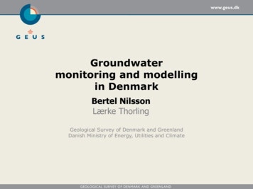
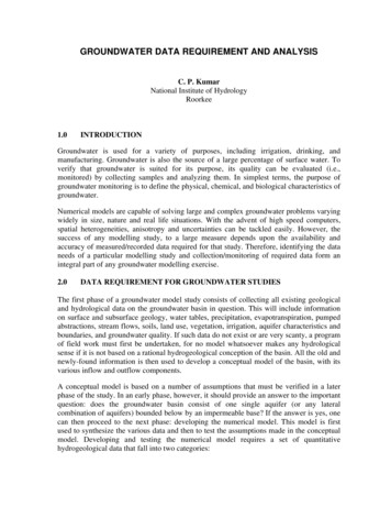
TETRA TECH, INC.1.0MARCH 2009INTRODUCTIONThis Semiannual Groundwater Monitoring Report (Report) prepared by Tetra Tech, Inc. (Tetra Tech), onbehalf of Lockheed Martin Corporation (LMC), presents the results of the Second Quarter 2008 and ThirdQuarter 2008 groundwater quality monitoring activities of the Beaumont Site 2 (Site) GroundwaterMonitoring Program (GMP).Groundwater monitoring is done in accordance with the approvedGroundwater Sampling and Analysis Plan (SAP) (Tetra Tech, 2007b).The Site is located southwest of the City of Beaumont, Riverside County, California (Figure 1-1).Currently, the Site is inactive with the exception of ongoing investigative activities performed underConsent Order (88/89 034) with the Department of Toxic Substances Control (DTSC).The objectives of this Report are to: Briefly summarize the Site history; Document the water quality monitoring procedures and results; Analyze and evaluate the water quality monitoring data generated; and Re-evaluate the current Site GMP.This Report is organized into the following sections: 1) Introduction, 2) Summary of MonitoringActivities, 3) Groundwater Monitoring results, 4) Summary and Conclusions. A summary of recentenvironmental activities and the current conceptual site model (CSM) can be found in Appendix A.1.1SITE BACKGROUNDThe Site is a 2,668 acre parcel located southwest of Beaumont, California. The parcels that comprise theSite were owned by individuals and the United States (U.S.) government prior to 1958. Between 1958and 1960, portions of the Site were purchased by the Grand Central Rocket Company (GCR) and utilizedas a remote test facility for early space and defense program efforts. In 1960, Lockheed AircraftCorporation (LAC) purchased one-half interest in GCR. GCR became a wholly-owned subsidiary ofLAC in 1961. The remaining parcels of land that comprise the Site were purchased from the U.S.government between 1961 and 1964.In 1963, Lockheed Propulsion Company (LPC) became anoperating division of LAC and was responsible for the operation of the Site until its closure in 1974. TheSite was utilized by GCR and LPC from 1958 to 1974 for small rocket motor assembly, testingoperations, propellant incineration, and minor disposal activities. Ogden Labs is known to have leasedportions of the Site in the 1970s (Radian, 1986a).Semiannual Groundwater Monitoring ReportSecond Quarter 2008 and Third Quarter 2008Beaumont Site 21-1
TETRA TECH, INC.MARCH 2009In 1989, the DTSC issued a consent order requiring LMC to cleanup contamination at the Site related topast testing activities (CDHS, 1989). Based on investigative and cleanup activities performed at the Site,the DTSC issued a no further remedial action letter to LMC in 1993.Semiannual Groundwater Monitoring ReportSecond Quarter 2008 and Third Quarter 2008Beaumont Site 21-2
RialtoX:\GIS\Lockheed 23522-0103\Region.mxdLake ElsinoreRiversideColtonLomaLindaSan BernardinoPerrisMoreno ValleyRedlandsHighlandBeaumont Site 2BeaumontHemetSan JacintoCalimesaYucaipaNWS San JacintoNWS BeaumontBanningRiverside CountySan Bernardino County5MilesFigure 1-1Regional Location ofBeaumont Site 2Beaumont Site 2Beaumont Site 2Property BoundaryNational WeatherService StationLEGENDU.S. Census Bureau TIGER line data, 2000.Adapted from:0
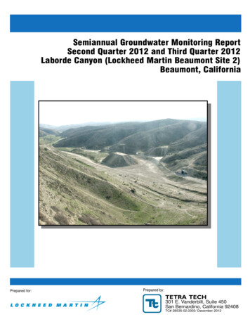
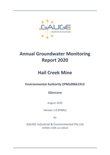
TETRA TECH, INC.MARCH 2009Based on regulatory interest in perchlorate and 1,4-dioxane, a groundwater sample was collected from aninactive groundwater production well (identified as W2-3) at the Site in January 2003. The sample wasanalyzed for volatile organic compounds (VOCs), perchlorate, and 1,4-dioxane to determine the potentialpresence and concentration of those chemicals in groundwater. The analytical results indicated thatVOCs and 1,4-dioxane were not present at or above their respective method detection limits (MDLs).However, perchlorate was reported at a concentration of 4,080 micrograms per liter (µg/L), whichexceeded the California Department of Health Services drinking water notification level (DWNL) whichexisted at that time of 6 µg/L. In October 2007 the DWNL was replaced by the California Department ofHealth Maximum Contaminant Level (MCL) of 6 µg/L. Based on the detection of perchlorate in thegroundwater sample collected, the DTSC reopened the Site for further assessment.Four (4) primary historical operational areas have been identified at the Site (Figure 1-2).Eachoperational area was responsible for various activities associated with rocket motor assembly, testing, andpropellant incineration. A brief description of each operational area follows:Historical Operational Area J (Area J) –Final AssemblyRocket motor casings with solid propellant were transported to Building 250 where final assembly of therocket hardware was conducted. The building was used from 1970 to 1974 for final assembly andshipment of short range attack missile rocket motors.Rocket motor assembly operations includedinstallation of the nozzle and headcap, pressure check of the motor, installation of electrical systems, andpreparations for shipment. During plant closure in 1974, all usable parts of this facility were dismantled,taken off the Site, and sold (Radian, 1986a).Historical Operational Area K (Area K) – Test Bays and Miscellaneous FacilitiesThe primary features included a large earthen structure known as the “Prism,” conditioning chambers, acentrifuge, and four test bays and two associated bunkers.The Prism was reportedly built between 1984 and 1990 and was used to test radar by General Dynamics(Tetra Tech, 2007a). Details concerning construction of the Prism are not available, but it appears to havebeen constructed with soils from near the test bays.The conditioning chambers were used to examine the effects of extreme temperatures on rocket motorsand to meet specification requirements (Radian, 1986a). A centrifuge was located in the northwesternportion of Area K, where rocket motors were tested in order to determine if the solid propellant wouldseparate from its casing under increased gravitational forces.Semiannual Groundwater Monitoring ReportSecond Quarter 2008 and Third Quarter 2008Beaumont Site 21-4
1962 RWQCB PermittedDischarge AreaHistorical Operational Area KTest Bays & Misc. W2-18MW 2-4TT-MW2-7DTT-MW2-7Disposal SiteHistorical Operational Area MGarbage Disposal AreaHistorical Operational Area LPropellant Burn MW2-9DTT-MW2-24TT-MW2-4STT-MW2-4DMW 2-2TT-MW2-11TT-MW2-1TT-MW2-12W 2-3TT-MW2-5W 2-1TT-MW2-21Liquid WasteDisposal PondsSmall BunkerTT-MW2-13TT-MW2-10MW 2-5TT-MW2-3Water Tanksand Pump HouseParking AreaMW 2-6TT-MW2-17S/DPrismLargeBunkerW 2-2Parking AreaTT-MW2-16W 2-5TT-MW2-2TT-MW2-14PropellantBurn SiteT-RevetmentConditioning Chambers"YConditioningChambersofTest BaysCentrifugeConcrete MountBuilding 250Rocket AssemblyBuildingArm of Y""No rth ernHistorical Operational Area JFinal Assemblyrm"Y Ste m Are a"X:\GIS\Lockheed 23522-0103\Op Areas.mxdnAteres"W2,000FeetLEGENDMarch 2007 aerial photograph.1,000Figure 1-2Historical Operational Areasand Site FeaturesRevisedBeaumont Site 2Disposal and Propellent Burn Siteperimeters are estimated (Radian, 1986a).Note: Beaumont Site 2 property boundary fromHillwig-Goodrow survey, May 2004.Liquid Waste Disposal AreaRWQCB PermittedDischarge AreaHistorical OperationalArea BoundaryBeaumont Site 2Property BoundaryReported ProductionWell LocationDestroyed MonitoringWell LocationDestroyed ProductionWell LocationGroundwater MonitoringWell LocationAdapted from:0
TETRA TECH, INC.MARCH 2009Previously, only three test bays were known; however, a former employee reported during a recentinterview that a fourth test bay [located north of the other three bays] was also previously used in Area K.The initial testing activities had a history of explosions that destroyed complete test areas, especiallyduring the period when GCR operated at the Site (Radian, 1986a). While vestiges from three test bays arecurrently visible at the Site, the fourth was reportedly destroyed by such an explosion during testing.Also reportedly, after motor failure, the area was checked to recover unburned propellant.Historical Operational Area L (Area L) – Propellant Burn AreaSolid propellant was reportedly transported to the burn area and set directly on the ground surface forburning (Radian, 1986a). No pits or trenches were dug as part of the burning process. The solidpropellant was saturated with diesel fuel to initiate combustion. Reportedly, the solid propellant wouldburn rapidly. There is no evidence or physical features that identify the precise location of burningactivities. Two production wells were located in this area (W2-1 and W2-3). W2-1 was reported to havebeen part of the agricultural homestead. The origin of W2-3 is unknown. The use of the wells isunknown. A waste discharge permit from 1962 was recently discovered indicating that up to 5,000gallons per year of waste water from rocket testing operations could be discharged into small surfacedepressions located in a small side canyon just south of Area L.Historical Operational Area M (Area M) – Garbage Disposal SiteA garbage disposal area was located adjacent to a small creek at the Site (Radian, 1986a). Scrap metal,paper, wood, and concrete materials were disposed of at the disposal site by LPC. Hazardous materials,including explosives and propellants, were never disposed of at the disposal site by LPC according toemployee interviews. Ogden Labs, a company that tested valves and explosive items, also used thisdisposal site.Reportedly, Ogden Labs disposed hazardous waste at the disposal site.In 1972, aLockheed Safety Technician was exposed to toxic vapors of unsymmetrical dimethyl hydrazine (u-DMH)from a pressurized gas container located within the disposal site. Based on potential exposure risks tooccupants, LPC’s safety group required Ogden Labs to take measures to remove any potentiallyhazardous materials at the disposal site. Shortly thereafter, a disposal company was contracted by OgdenLabs to clean up the disposal site (Radian, 1986a)Semiannual Groundwater Monitoring ReportSecond Quarter 2008 and Third Quarter 2008Beaumont Site 21-6
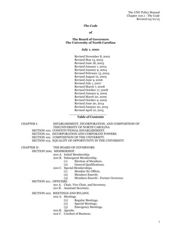
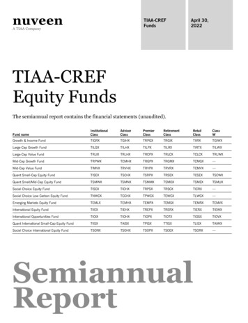
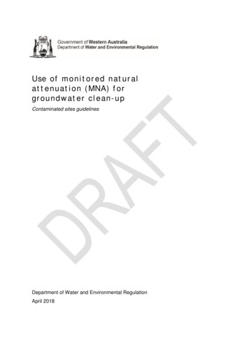
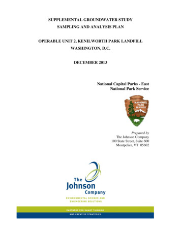
TETRA TECH, INC.2.0MARCH 2009SUMMARY OF MONITORING ACTIVITIESSection 2 summarizes the Second Quarter 2008 and Third Quarter 2008 groundwater monitoring eventsconducted at the Site. The results from these monitoring events are discussed in Section 3.0.2.1GROUNDWATER LEVEL MEASUREMENTSThe Second Quarter 2008 groundwater level measurements were collected from 28 monitoring wells andone (1) piezometer on May 15, 2008. The Third Quarter 2008 groundwater level measurements werecollected from 30 monitoring wells and one (1) piezometer on August 11, 2008. Figure 2-1 presents asite map showing the well locations. Copies of the field data sheets from the water quality monitoringevents are presented in Appendix B. A summary of well construction details is presented in Appendix C.2.2GROUNDWATER SAMPLINGThe GMP has a quarterly, semiannual, and annual frequency. Both groundwater and surface water aresampled as part of the GMP. The annual event is the major monitoring event and the quarterly andsemiannual events are smaller, minor events. All new wells are sampled quarterly for one year afterwhich they are evaluated and reclassified. The semiannual event includes, horizontal extent, verticaldistribution, increasing contaminant, and guard wells, and are sampled during the 2nd and 4th quarter ofeach year. In addition to the quarterly and semi annual wells, the annual event includes background wellsand takes place during the 2nd quarter of each year. The groundwater monitoring schedule is reviewedand modified as necessary annually during the Second Quarter groundwater monitoring event.Modifications are done in accordance with the approved SAP. Second Quarter 2008 and Third Quarter2008 follow the schedule proposed in the Second and Third Quarter 2007 monitoring report (Tetra Tech,2008a) which was presented to the DTSC in March 2008 and approved with no comments. During theSecond Quarter 2008 monitoring event 26 groundwater samples and two (2) surface water samples werecollected between May 20 and May 29, 2008. During the Third Quarter 2008 monitoring event nine (9)groundwater samples and two (2) surface water samples were collected between August 26 andSeptember 2, 2008. Table 2-1 and 2-2 lists the wells monitored for the Second Quarter 2008 and ThirdQuarter 2008 monitoring events, analytical methods, sampling dates, and Quality Assurance/QualityControl (QA/QC) samples collected. Groundwater sampling, analytical, and QA/QC procedures for themonitoring event were described in the Groundwater Monitoring Well Installation Work Plan (TetraTech, 2004a) and the SAP. Figures 2-2 and 2-3 illustrate the well locations sampled.The following water quality field parameters were observed and recorded on field data sheets (AppendixB) during well purging activities: water level, temperature, pH, electrical conductivity (EC), turbidity,dissolved oxygen (DO) and oxidation reduction potential (ORP). Collection of water quality parametersSemiannual Groundwater Monitoring ReportSecond Quarter 2008 and Third Quarter 2008Beaumont Site 22-1
TETRA TECH, INC.MARCH 2009was initiated when at least one (1) discharge hose / pump volume had been removed and purging wasconsidered complete when the above parameters had stabilized, or the well was purged dry (evacuated).Stabilization of water quality parameters was used as an indication that representative formation waterhad entered the well and was being purged. The criteria for stabilization of these parameters are asfollows: water level 0.1 foot, pH 0.1, and EC 3%, turbidity 10 nephelometric turbidity units(NTUs) (if 10 NTUs 10%), DO 0.3 mg/L and ORP 10 mV. Sampling instruments and equipmentwere maintained, calibrated, and operated in accordance with the manufacturer’s specifications,guidelines, and recommendations. Groundwater samples were collected from the monitoring wells bylow-flow purging and sampling through double valve sampling pumps. Dedicated double valve samplingpumps are installed in all of the monitoring wells on the Site with the exception of TT-MW2-3, where aportable bladder pump is used, and TT-MW2-19S which was hand bailed and sampled with a disposablebailer.For the Second Quarter 2008 and Third Quarter 2008 monitoring events, every effort was made to collectgroundwater samples in order of increasing perchlorate and TCE concentration. Samples were placed inappropriate EPA method specified containers. A sample identification label was affixed to each samplecontainer, and sample custody was maintained by a chain-of-custody record. Groundwater samplescollected for the monitoring events were chilled and transported to EMAX Laboratories, Inc., a stateaccredited analytical laboratory, via courier, thus maintaining proper temperatures and sample integrity.Trip blanks (LTBs) were collected for the monitoring events to assess cross-contamination potential ofwater samples while in transit. Equipment blanks (LEBs) were collected when sampling with nondedicated equipment to assess cross-contamination potential of water samples via sampling equipment.Semiannual Groundwater Monitoring ReportSecond Quarter 2008 and Third Quarter 2008Beaumont Site 22-2
1962 RWQCB PermittedDischarge AreaHistorical Operational Area KTest Bays & Misc. FacilitiesTT-MW2-17S/D"W 2-1TT-MW-24TT-MW-22TT-MW-23TT-MW-21W 2-2TT-PZ2-1TT-MW2-5MW 2-4W 2-3Historical Operational Area MGarbage Disposal quid WasteDisposal PondsHistorical Operational Area LPropellant Burn AreaMW 2-2TT-MW2-11TT-MW2-1TT-MW2-18TT-MW2-13MW MW2-10TT-MW2-12MW 2-5TT-MW2-14TT-MW2-3TT-MW2-2"NorthernArm ofY"W 2-5m Area"Historical Operational Area JFinal AssemblyYof"Y SteX:\GIS\Lockheed 23522-0103\Site.mxd"WrmnAteres1,0002,000FeetFigure 2-1Site MapRevisedBeaumont Site 2Note: Beaumont Site 2 property boundary fromHillwig-Goodrow survey, May 2004.Liquid Waste Disposal AreaRWQCB PermittedDischarge AreaHistorical OperationalArea BoundaryBeaumont Site 2Property BoundaryReported ProductionWell LocationDestroyed MonitoringWell LocationDestroyed ProductionWell LocationGroundwater MonitoringWell LocationLEGENDAdapted from: March 2007 aerial photograph.0
TETRA TECH, INC.MARCH 2009Table 2-1 Sampling Schedule and Analysis Method - Second Quarter 2008Monitoring A 314.0)Title 22 MetalsTotal andDissolved(SW6010B/7470)NDMA(EPA 1625B)RDX(SW 1/0805/29/08XXXXXX--Notes:Comments andQA /QC SamplesMS/MSD - DuplicateMS/MSD - DuplicateDuplicateSecond Quarter 2008: Total Sample Locations:28Total Samples Collected:28EPA -QA / QC VOCs NDMARDXMS / MSD-United States Environmental Protection Agency.Quality Assurance / Quality Control.Volatile Organic CompoundsN-nitrosodimethylamineRoyal Demolition ExplosivesMatrix Spike / Matrix Spike Duplicate.Semiannual Groundwater Monitoring ReportSecond Quarter 2008 and Third Quarter 2008Beaumont Site 22-4
TETRA TECH, INC.MARCH 2009Table 2-2 Sampling Schedule and Analysis Method - Third Quarter 2008Monitoring WellLocationSampleDateVOCs(EPA 8260B)Perchlorate(EPA 314.0)General MineralsParameters 08/27/08-X-TT-MW2-2108/26/08XXXComments andQA /QC /08XXXMS/MSDTT-MW2-2408/26/08XXXDuplicateNotes:EPA -QA / QC VOCs MS / MSD-Third Quarter 2008: Total Sample Locations:11Total Samples Collected:United States Environmental Protection Agency.11Quality Assurance / Quality Control.Volatile Organic CompoundsMatrix Spike / Matrix Spike Duplicate.Semiannual Groundwater Monitoring ReportSecond Quarter 2008 and Third Quarter 2008Beaumont Site 22-5
1962 RWQCB PermittedDischarge AreaLiquid WasteDisposal AreaTT-MW2-16Historical Operational Area LPropellant Burn AreaWS-1 TopTT-MW2-20DTT-MW2-20SWS-1 2-11Historical Operational Area MGarbage Disposal -12TT-MW2-4STT-MW2-21TT-MW2-14Historical Operational Area KTest Bays & Misc. FacilitiesTT-MW2-2Historical Operational Area JFinal Assemblyy onLabo rde C anX:\GIS\Lockheed 23522-0103\Samp Points Q208.mxd1,5003,000FeetFigure 2-2Second Quarter 2008Sample LocationsRevisedBeaumont Site 2Note: Beaumont Site 2 property boundary fromHillwig-Goodrow survey, May 2004.Liquid Waste Disposal AreaRWQCB PermittedDischarge AreaBeaumont Site 2Property BoundaryHistorical OperationalArea BoundarySurface WaterSampling LocationGroundwater MonitoringWell LocationLEGENDAdapted from: April 2007 aerial photograph.0
1962 RWQCB PermittedDischarge AreaTT-MW2-23Liquid WasteDisposal AreaHistorical Operational Area KTest Bays & Misc. FacilitiesTT-MW2-22TT-MW2-21Historical Operational Area JFinal Assemblyy onLabo rde C anX:\GIS\Lockheed 23522-0103\Samp Points Q308.mxdWS-1 BottomTT-MW2-7DTT-MW2-24TT-MW2-20S/DWS-1 TopTT-MW2-19S/DHistorical Operational Area LPropellant Burn AreaHistorical Operational Area MGarbage Disposal Area3,000FeetLEGENDApril 2007 aerial photograph.1,500Figure 2-3Third Quarter 2008Sample LocationsRevisedBeaumont Site 2Note: Beaumont Site 2 property boundary fromHillwig-Goodrow survey, May 2004.Liquid Waste Disposal AreaRWQCB PermittedDischarge AreaBeaumont Site 2Property BoundaryHistorical OperationalArea BoundarySurface WaterSampling LocationGroundwater MonitoringWell LocationAdapted from:0
TETRA TECH, INC.2.3MARCH 2009SURFACE WATER SAMPLINGSurface water locations SW-01 through SW-07 are located in the ephemeral creek bed that runs throughLaborde Canyon. Surface water runoff collects in the creek during periods of heavy precipitation andruns south through the Site and the former Wolfskill property, eventually crossing under Gilman HotSprings Road. Water is present in the creek bed only during periods of heavy, prolonged precipitation.W
Quarter 2008 groundwater quality monitoring activities of the Beaumont Site 2 (Site) Groundwater Monitoring Program (GMP). Groundwater monitoring is done in accordance with the approved Groundwater Sampling and Analysis Plan (SAP) (Tetra Tech, 2007b). The Site is located southwest of the City of Beaumont, Riverside County, California (Figure 1-1).