Transcription
A Guide toEpoxy GroutingPreparation, Mixing,Installation and Testingof Epoxy Grouts
This Guide covers the mixing and installation instructions relating to the following Epoxy Resin Grouts:MasterFlow 400MasterFlow 648 - FlowableMasterFlow 648 - FluidIntroductionEpoxy Grouts are precision grouts, used to support and align critical equipment, transferring loads from theequipment baseplate to the foundation.A precision grout must:Grouting materials are selected based on the type of load they will support. Dynamic loads are associated withreciprocating equipment, motors, generators, turbines etc. Static loads are associated with columns or nonmoving equipment.Epoxy grouts offer unique performance advantages in many applications. They achieve strength quickly,allowing fast return to service or commissioning of equipment. Greater bond to the underside of a preppedbaseplate, density and lower modulus of elasticity help to absorb impact and vibration. Low shrinkage andhigh tensile and flexural strengths optimize load transfer ensuring stable, secure alignment and protectingequipment from unnecessary wear and tear. Chemical resistance properties ensure they are durable even inharsh industrial environments.With more than 100 years of experience in precision equipment grouting, Master Builders Solutions is an earlydeveloper and pioneer in both cementitious and epoxy grouts. We understand not only the in-serviceperformance demands that our grouts must meet, but also the inter-relationship between various physicalproperties and application criteria that must be carefully considered. Master Builders Solutions has appliedadvanced chemistry to balance the physical properties of compressive strength, bearing area, chemical andhigh temperature resistance, shrinkage and creep with the sometimes difficult yet also very importantapplication enablers of flow and working time, to provide uncompromised and durable support, protecting the1
equipment investment by improving reliability, operating efficiency and life cycle of machinery.The performance of any epoxy grout, in fact for most all construction materials, depends on the proper fit-forpurpose design, and the proper installation. This Guide to Epoxy Grouting is designed to help equipmentmanufacturers, engineers and specifiers, owners and contractors understand the Proper Preparation, Mixing,Installation & Testing of Epoxy Grouts to enable durable, quality, installations of MasterFlow Grouts.Further information on the engineering properties, design protocols and testing methods related to epoxygrouting can be found on our website, or from any of our dedicated Master Builders Solutions technical expertsacross the -ae/products/masterflowProper Preparation, Mixing, Installation & Testing of EpoxyGroutsFoundation PreparationBefore setting structural elements or machinery, all of the areas of the foundation which will be in contact withthe grout, including anchor bolt holes, must be properly prepared. The concrete foundation surface must bethoroughly cured, and roughened as specified, to expose sound aggregate.A fresh concrete surface may be uniformly roughened before it has set using a nail rake in one directiononly. Use of a bull float, darby, broom, or wood float finish, or scratching at random with a garden rake ortrowel is NOT recommended.For hardened concrete foundations, hand held, pistol grip pneumatic hammers with chisel point heads arerecommended for roughening to remove laitance and loose material. Use of large paving breakers equippedwith bush hammers, spade or chisel bits, are NOT recommended. Where grout will extend horizontally outbeyond the edge of the plate or object to be grouted, the foundation must also be prepared below these areasto help assure bond.All laitance and unsound material must be removed, and the foundation must be free of oil, grease, wax, curingmembranes and other contaminants. Surfaces should be clean and dry before application of the grout.If an anchor bolt sleeve is to be filled, be sure all water is removed. Use a siphon, vacuum pump, or rubberhose and bulb. Remove the residual moisture by either forced air or evaporation. If the anchor bolt sleevewill not be grouted, seal the bolt hole with felt, foam rubber or other means. Cover all shims, anchor boltsand leveling screws to keep the grout from adhering. Use model clay, glazing putty or anything of a puttyconsistency which will stick but not harden, holding down bolts can be provided with a “foam rubber” sleeveto prevent adhesion and allow room for movement without imparting stresses on the surrounding grout.Because the coefficient of thermal expansion of epoxy grout is higher than that of concrete or steel, grout thatextends to the edge of a foundation that has a 90 edge can lift or tear the concrete just below that edge.Never place grout near the edge of a concrete foundation that has a 90 corner or edge. Chamfer the edge ofthe concrete 45 degrees to about a 2" (51 mm) width. Chamfering the foundation edge will spread the upliftload and reduce the potential for edge lifting.2
Protect the foundation and equipment from rain or moisture. Areas not to be grouted must be sealed off. Shadethe foundation from summer sunlight for at least 24 hours before and 48 hours after grouting. Keeping thesurface covered will make the later job of cleaning the surface prior to grouting much easier and less costly.Plate and Equipment PreparationThe bonding surfaces of the base or plate to be grouted should be sandblasted to “white metal” and be freeof coatings, wax, grease or scale. Other mechanical methods such as grinding, or sanding are also effectivebut do not produce as high a bond strength as sandblasting. However, where new plant and equipmenthave been surface finished with high quality coating systems (e.g. polyurethane), these need not beremoved.Primer should be used ONLY when a long delay between cleaning and grouting could allow excessive rusting orcontamination. If the base must be primed, consult your local Master Builders Solutions sales representative for aprimer recommendation. If the primer has been on the surface for more than one month, abrade and solventwipe it so that no residue remainsSince the grout will come up at least 10–15 mm onto the equipment, it may be advisable to mask above thisarea with masking tape. To permit easy clean up, wax or cover all surfaces where the grout may splash.FormingConstruction of forms and grouting should follow as soon as practical after erection and alignment ofbaseplates are completed. The forms should be compatible with (1) the placement method to be used, (2)consistency at which the grout will be placed, and (3) the distance the grout must travel. Forms should be builtto facilitate continuous, quick and complete filling of the space with these factors in mind.Forms must be liquid tight and strong enough to withstand the hydraulic pressure of the grout, withoutleaking. Materials used in building forms include wood (the most common), polystyrene, steel and on rareoccasions such exotic material as plexiglass. Forming materials which are absorbent, such as wood, should becoated with wax, grease, or a plastic coating. These coatings act as bond breakers so that smooth groutsurfaces result after form removal, and the forms are protected for reuse.Seal wood forms to vertical concrete surfaces by applying putty or caulking below top of concrete, then pressform into place. The points to caulk are the interfaces between the form and rough foundation surface wheregrout might leak out during its placement or before setting. Material used for caulking between the form andconcrete surface may be joint sealants or epoxy mortars. Vertical joints in the forms should be caulked,especially if large cracks are evident. Caulking should be done on the outside edge of the form rather than theinside. The use of duct tape or “silver” tape applied on the inside of the form, at corners, is useful for this.Grout is preferably placed from only one direction, so forms should include a placing side, exit side, and sideforms, all of which direct and contain the grout under the object being grouted.Forms should extend vertically a minimum of 1 inch (25 mm) or higher than the underside of the bedplate of the3
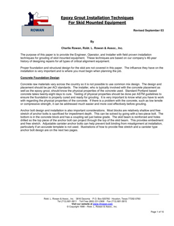
equipment to help ensure complete filling of the space to be grouted and prevent overflowing. The side formsshould not be tight against the plate but should be erected a minimum of 25 mm and a maximum of 100 mmfrom the edge base, rail or sole plate being grouted so that air being displaced is not trapped below the plate.Excessive edges create thermal stress and can result in cracking.A 50 - 75mm clearance is recommended at the area where the grout is to be placed. The vertical form on theexit side (opposite the placing side) should be extended 50 – 100 mm away from the plate so that straps orother placing aids can be inserted to assist movement of the grout should that become necessary. Largenon- supporting grout areas should be eliminated wherever possible.TYPICAL HEADER BOXThe form on the placing side can be constructed to extend 50 –100 mm horizontally from the plate at thefoundation, slanted upward at an approximate 45º angle to facilitate placement. A back board, or splashboard form should be built on top of the plate and at the plate edge, opposite the slanted headboard, toprevent spillage of grout and provide containment of the “head” of grout as it is being placed. This will allowgrout to be placed with a minimum of turbulence (and entrapment of air bubbles) while directing it smoothlyunder the plate. The further the grout must travel horizontally, the higher the slanted head box should be fora given consistency. This is to provide “head” pressure to direct the grout around shims, leveling screws,bolts, keys and other obstructions, to the exit side.Alternatively, moderately sized equipment such as turbines and generators, or other base plates of lengthydimensions, may utilize a portable “head box” which can be moved along the length of the plate as thegrouting proceeds. This portable head box is a way to facilitate continuous flow of the grout and minimizeforming costs. The box should utilize a head form sloped at 45 degrees that rests in part of the form, floor and/or baseplate. This method serves just as well, and often better than a long-sloped form, as the thrust of thegrout flow is better controlled.Edge ChamfersEliminating sharp corners in the grout reduces stress concentration.For Epoxy grouts, the chamfers can’t be trimmed easily (Grinding is an option). Therefore, the chamferededges need to be built into the forms, by 1 – 2 inches (25 – 50 mm) using chamfer strips on the forms. (SeeSection, Causes and Prevention of Edge lifting in Epoxy Grouts later in this grout manual for furtherexplanation).4
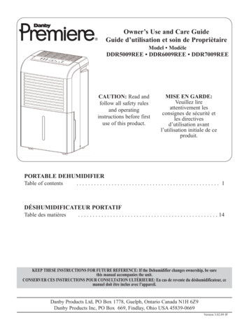
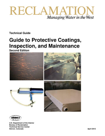
Shoulders of epoxy grouted equipment should be kept as small as practically possible and ideally their width (X)should always be less than their thickness (Y)Deep Pour Recommendations – Reinforcing Bar Installation for MasterFlow 648Epoxy GroutThe use of reinforcement bars is recommended where the total thickness of the MasterFlow 648 grout isgreater than 150 mm to minimize cracking and help draw excessive heat down into the base slab andtransfer stress if cracks do occur.The top tier should be located about 50 mm below the equipment base. A bottom tier should be located about50 mm above the foundation surface. Additional tiers, if required, should be spaced equal distances in thegrout pour with vertical supports as required.A typical rebar layout is shown in Figure 1. Most rebar should run lengthwise in the grout with cross bars andvertical dowels placed at approximately 300 – 600 mm intervals as shown in Figure 1. Rows of rebar shouldbe between 150 – 300 mm apart. Grout pours of 150 mm would require only one layer of horizontal rebar.Pours of 250 mm can benefit from an extra layer as shown in Figure 2.The horizontal rebar should be wired to vertical dowels that are grouted into the concrete base as shown inFigure 2. The horizontal and vertical bars are recommended to be constructed of Ø13 mm rebar and shouldbe embedded to a depth of at least 150 mm in the concrete. The bars should be grouted with a speciallyformulated rebar anchor grout such as MasterFlow 932 AN. None of the rebar should be closer than 50 mm5
to the nearest grout surface (Figure 3).All rust, dirt and grease should be removed from the rebar prior to installation. Grit blasting will provide bestadhesion (if allowed)Epoxy grouts can also be placed in lifts. Silica sand is broadcast onto the first lift to provide an intermediatebondable surface, and the subsequent lift can proceed after about 24 hours when the first lift has hardened andcooled to the ambient temperature.Epoxy Grout Application Thickness (in a single lift)MasterFlow 400 – 25mm up to 100mmMasterFlow 648 Fluid – 50mm up to 150mmMasterFlow 648 Flowable – 100mm up to 300mmThese are recommended maximum thicknesses applied in a single lift and are to a certain degree determined byambient temperatures at the time of mixing and placing.Mixing of Epoxy GroutsTools1.Clean and dry 20 Litre metal or heavy duty plastic buckets2.Plenty of rags for wiping hands and tools.3.A supply of citrus degreaser or solvent for cleaning hands and tools –Optional. MasterFlow 648 can be cleaned with soap and water.4.Rubber Gloves and all other appropriate PPE.Grout Handling1.Aggregate must be completely dry. It should be stored under cover and on pallets.2.In cold weather, store all the components in a warm place for at least 24 hours; 20-25ºC is preferred.3.In hot weather, store in an air-conditioned container for at least 48 hours prior to being needed.MixingDo not add solvent, water or any other material to the grout. Do not alter the Part A to Part B resin proportions –Mix ONLY full kits.Mix the grout as clos
epoxy grouting preparation, mixing, installation and testing of epoxy grouts 7klv *xlgh fryhuv wkh pl[lqj dqg lqvwdoodwlrq lqvwuxfwlrqv uhodwlqj wr wkh iroorzlqj (sr[\ 5hvlq *urxwv 0dvwhu)orz 0dvwhu)orz )orzdeoh 0dvwhu)orz )oxlg ,qwurgxfwlrq (sr[\ *urxwv duh suhflvlrq jurxwv xvhg wr vxssruw dqg doljq fulwlfdo htxlsphqw wudqvihuulqj ordgv iurp wkh htxlsphqw edvhsodwh wr wkh irxqgdwlrq .