Transcription
WHITE PAPERPROPER SELECTION OFCONTROL CIRCUITTRANSFORMERSBULLETIN 1497, 1497A, AND 1497BCONTROL CIRCUIT TRANSFORMERSThe proper selection of the control circuit transformers is importantfor suitable operation and proper function of electromagneticdevices. This paper outlines the importance of proper selection ofcontrol circuit transformers. It discusses both the key considerationsand two methods of selecting transformers.Bulletin 1497ABulletin 1497Bulletin 1497B
Bulletin 1497 Control Circuit Transformers2
Bulletin 1497 Control Circuit TransformersTable ofContentsWhat is a Control Circuit Transformer? . . . . . . . . . . . . . . . . . . . . . . . . . . . . . . . . . . . . . 4Inrush Volt-Ampere and Sealed Volt-Ampere Considerations . . . . . . . . . . . . . . . . . 4Secondary Voltage Considerations . . . . . . . . . . . . . . . . . . . . . . . . . . . . . . . . . . . . . . . . 5600V Primary Device Considerations . . . . . . . . . . . . . . . . . . . . . . . . . . . . . . . . . . . . . . . 5Long Wire Runs Considerations . . . . . . . . . . . . . . . . . . . . . . . . . . . . . . . . . . . . . . . . . . . 6Control Circuit Transformer Selection Methods . . . . . . . . . . . . . . . . . . . . . . . . . . . . . 6Method I: Short and Conservative Means of Selecting Control Circuit Transformers . 6Method II: Detailed Procedure of Selecting Control Circuit Transformers . . . . . . . . . . 7European Common Market Considerations . . . . . . . . . . . . . . . . . . . . . . . . . . . . . . . . 12Summary . . . . . . . . . . . . . . . . . . . . . . . . . . . . . . . . . . . . . . . . . . . . . . . . . . . . . . . . . . . . . . 1333
Bulletin 1497 Control Circuit TransformersWhat is aControl CircuitTransformer?A control circuit transformer is a device designed to provide a reduced control voltage forenergizing the coils of electromagnetic devices such as motor starters, contactors, relays,and timers. These devices make up the majority of the loads supplied by the control circuittransformer. Control circuit transformers are also referred to as Industrial ControlTransformers, Machine Tool Transformers, and Control Power Transformers.InrushVolt-Ampereand SealedVolt-AmpereConsiderationsThe proper size, or the VA rating, of the control circuit transformer is important. It will be adetermining factor in the life of the transformer, which ultimately will reflect on the properoperation of control devices that it supplies. The methods of selecting transformer VAratings addressed in this technical paper are applicable to 50 3000 VA control circuittransformers.The transformers used in this application fall into the dry type insulation category. Typicalprimary voltages in the United States are 600, 480, 240, and 208. Transformers can also bemanufactured with special primary and secondary voltage combinations.There are two VA values to be considered when selecting a transformer. Energizingelectromagnetic components creates a large momentary surge current, commonly referredto as inrush VA. This is the first VA value to be considered. The inrush VA will lastapproximately 5 20 milliseconds and can have a value as high as ten times thetransformer's nameplate rating. Thus, the inrush VA will be high in value and short induration. A properly selected control circuit transformer is designed to handle themomentary inrush VA and at the same time maintain a secondary voltage within a setrange.The second value to be considered is the sealed VA, the amount of volt-amperes requiredto maintain the energized state of an electromagnetic device. This VA requirement will be5 10 times less than the inrush VA.In the United States, compliance with NEMA Standard ICS 2-110 is another importantconsideration. The NEMA Standard requires the alternating current contactor tosuccessfully close at 85% of its coil rated voltage. For example, an alternating currentcontactor with 120 volt rated coil must be able to successfully close at 102 volts which is85% of its rated voltage.4
Bulletin 1497 Control Circuit TransformersWhen a transformer is used with a contactor or starter, the contactor or starter mustsuccessfully pick-up at 90% of the rated line voltage of the transformer. The purpose of thisNEMA Standard requirement is to:1. Establish a standard or policy for the operation of the control device.2. Coordinate values for the control device and the control circuit transformer.3. Set known limits to address the inherent transformer voltage drop due to the inrush currentfrom an unsealed alternating current electromagnet.For example, a transformer with a rated line voltage of 480 volts, a rated secondary voltage of120 volts, and an operating voltage at 90% of the line voltage would have 432 volts on theprimary of the transformer. This would result in a theoretical 108 volts on the secondary, basedon the turns-ratio, assuming no voltage drop through the transformer. Properly selectedtransformers must limit the voltage drop under inrush conditions such that 95% of the ratedsecondary voltage occurs with 100% of the rated line voltage applied. Combining these twoconditions result in a secondary voltage of approximately 102 volts which meets the contactorpick-up requirement.SecondaryVoltageConsiderationsThe secondary voltage that is present when a light load or no load is attached to thetransformer should also be considered. Open circuit secondary voltages (no load) can be 10%higher than nominal with nominal input voltages applied. This means that a 480 120 volttransformer with full 480 volts applied to the primary, can have 132 volts available at thesecondary terminals. When you add the effect of high line input condition (528 volts) to thisoutput, the secondary can reach over 145 volts. This is a worst case condition, but not out ofthe question. This makes it even more important to size the transformer correctly for theapplication and understand that the secondary voltage is designed to be nominal rated voltagewhen loaded to the nameplate VA. Oversizing the transformer only serves to make thiscondition worse.600V PrimaryDeviceConsiderationsThe Allen-Bradley Bulletin 1497, 1497A, and 1497B transformer product line includes primaryvoltage ratings that span from 115 600V AC. Special design attention has been applied to the575 600V AC designs to address the potential failure of 600V units when exposed to lineaberrations or events such as surges and spikes frequently caused by switched capacitor banksor the connection of certain types of electrical equipment, such as welders and platingequipment, to the circuit.In general, standard transformer construction for a 600V AC primary design tends to be moresusceptible to these problems than lower primary designs. Allen-Bradley Bulletin 1497, 1497A,and 1497B 600V units have been strengthened in terms of insulating materials and windingseparation to provide a robust product capable of withstanding all but the most severe of thesefrequently encountered line conditions.55
Bulletin 1497 Control Circuit TransformersLong Wire RunsConsiderationsAnother consideration in the selection of the transformer is long wire runs. These occur ifthe control devices requiring power are located away from the transformer. When a longwire run is present, the resistance and capacitance cause a voltage drop to the controldevice. If the voltage drop is severe enough, the control device may not pick-up. Toaddress this, the transformer must be selected taking this voltage drop into account. Aninterposing relay may also be required. Voltage drop calculators are available fromnumerous internet sites.Control CircuitTransformerSelectionMethodsMethod I: Short and Conservative Means of Selecting ControlCircuit TransformersMethod 1 provides a short and conservative means that will yield a sufficiently sizedtransformer. Assuming that all control devices, including the transformer, are locatedwithin the same unit, the steps are as follows:1. Calculate the total sealed volt-ampere burdens of all the devices that could be sealedat any one time;2. Multiply the value from Step 1 by 1.25;3. Calculate the maximum inrush volt-amperes of the closing device or devices;4. Add the maximum inrush volt-amperes of closing device or devices calculated inStep 3 to the required sealed VA calculated in Step 2;5. Divide the maximum VA calculated in Step 4 by 4.Using the larger of the two values calculated in Steps 2 and 5, select a transformer whoseVA rating is: Closest to, but not lower than, the larger calculated value; and Greater than the total sealed VA requirementThe above method of selecting a transformer is only applicable to Allen-Bradley Bulletin1497, 1497A, and 1497B control circuit transformers. Many standard transformers fromother manufacturers are built to different manufacturing standards and have higher losses(lower output voltage) and thus, would require larger VA ratings than calculated by thismethod.6
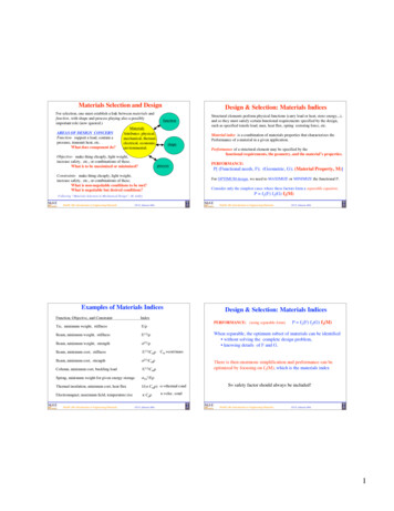
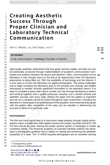
Bulletin 1497 Control Circuit TransformersMethod II: Detailed Procedure of Selecting Control CircuitTransformersMethod 2 is a detailed procedure of selecting a control circuit transformer for a single relay orcontactor and is important when other considerations are required, such as, high operatingtemperatures and long wire runs. When using this method of selection, technical data such asload operating temperature, frequency, impedance, reactance and resistance may be neededfor load devices. However, this type of data is proprietary for many manufacturers. Thespecific transformer application will determine the data actually needed for proper selection ofa control circuit transformer.Transformer regulation curves are required for proper selection of transformers. Eachtransformer has a regulation curve for different power factors. The complete family oftransformer regulation curves, which are available from the manufacturer, may be necessary toselect the proper transformer. Examples of transformer regulation curves are shown in Figure 1.Figure 1. Transformer Regulation CurvesIn order to determine if the size or VA rating of a particular transformer is acceptable, an inrushimpedance load line for the load must be calculated and then plotted on the transformerregulation curves. The power factor of the load must also be determined. The point where theload's power factor curve intersects the impedance load line is needed to determine if thepercent rated secondary voltage of the particular transformer is acceptable. If not, theprocedure is repeated using the regulation curves of a different VA rated transformer.Allen-Bradley Bulletin 1497, 1497A and 1497B transformers properly applied will provide the85% minimum secondary voltage per NEMA standards with 90% of the rated voltage on theprimary. As discussed earlier, this condition is met if under inrush conditions the secondaryvoltage is not allowed to drop below 95% of its rating with 100% of the rated voltage on theprimary.77
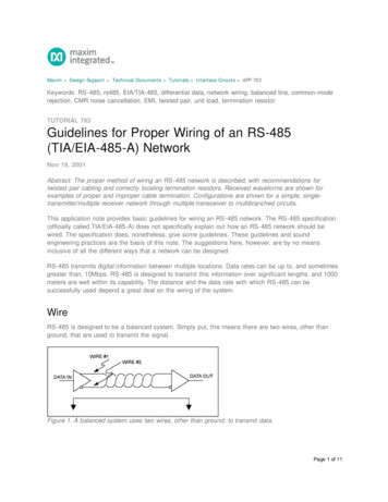
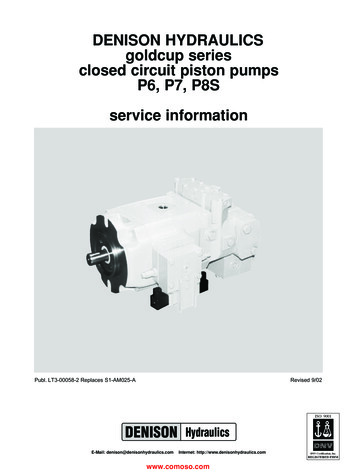
Bulletin 1497 Control Circuit TransformersThe following example (Figure 2) uses the Allen-Bradley Bulletin 1497 75VA transformerregulation curves.Figure 2. Allen-Bradley Bulletin 1497 75VA Transformer Regulation CurvesGiven: Load Allen-Bradley Bulletin 509 Size 1 starterAssume: Cold coil resistance 53.4Ω @ 20 CInrush VA 192Coil rated voltage 120V @ 60 HzCalculations:Starter inrush current @ 100% secondary voltage (II):II VAInrush VSec 192 120 1.6AImpedance of load @ 20 C (Z):Z VSec II 120 1.6 75ΩReactance of load @ 20 C (X):X (Z2 - R2)1/2 ((75)2 - (53.4)2)1/2 52.67Ω8
Bulletin 1497 Control Circuit TransformersPercent power factor of load @ 20 C (PF):PF (R Z) 100 (53.4 75) 100 71.2%The impedance load line, to be calculated, must intersect the 75VA transformer regulationcurve at the calculated power factor of 71.2%, and at 95% of rated secondary voltage in orderto be acceptable. Two points are calculated to establish the impedance load line.Rated secondary current (ISec):ISec VA VSec 75 120 0.625 APercent rated secondary current @ 100% secondary voltage (%ISec):%ISec (II ISec) 100 1.6 0.625 100 256%At 100% rated secondary voltage the percent rated secondary current is equal to 256%. Thisdata locates the upper point of the impedance load line.Starter inrush current @ 70% secondary voltage (II1):II1 II .7 1.6 .7 1.12 APercent rated secondary current @ 70% secondary voltage (%ISec1):ISec1 (II1 ISec) 100 (1.12 0.625) 100 179.2%At 70% rated secondary voltage the percent rated secondary current is equal to 179.2%. Thisdata locates the lower point of the impedance load line.Draw the load line between these points.99
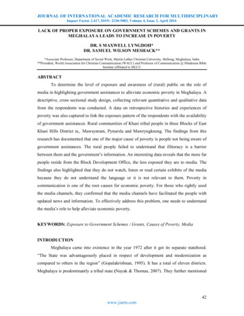
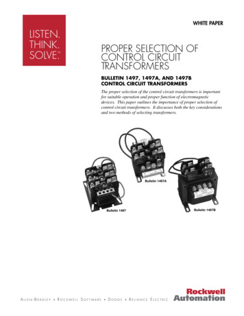
Bulletin 1497 Control Circuit TransformersReferring to Figure 3, locate the 71.2% inrush power factor on the load line, byinterpolating between the regulation curves. This point can be read on the vertical axis, asthe transformer's rated secondary voltage (in %) occurring during inrush. It should be 95%or higher. In this example, it is approximately 95.5 percent, and the application isacceptable.Figure 3.However, if this starter was operated after its coil had reached operating temperature orwas operated in a jogging or plugging application, the calculations would have to take intoconsideration the elevated coil temperature.Using the data from the previous example and the additional data following, thecalculations would be as follows:Assume: Hot coil operating temperature 110 CCalculations:Coil resistance at 110 C (R):R ((234.5 T2) (234.5 T1)) R@20 C (344.5 259.5) 53.4 70.9ΩReactance of load @ 110 C (X):X10 X@20 C 52.67Ω
Bulletin 1497 Control Circuit TransformersImpedance of load @ 110 C (Z):Z (X2 R2)1/2 ((52.67)2 (70.9)2)1/2 88.3ΩStarter inrush current @ 100% secondary voltage @ 110 C (II2):II2 VSec Z 120 88.3 1.36APercent power factor of load @ 110 C (PF):PF (R Z) 100 (70.9 88.3) 100 80.3%The impedance load line, to be calculated, must intersect the 75VA tra
The proper size, or the VA rating, of the control circuit transformer is important. It will be a determining factor in the life of the transformer, which ultimately will reflect on the proper operation of control devices that it supplies. The methods of selecting transformer VA ratings addressed in this technical paper are applicable to 50 3000 VA control circuit transformers. The .