Transcription
1nMODEL 225P/230PULTRASOUNDI /;; I---- -: ----ImPERATmR'S MANUAL INSTALLATION mPERATimN MAINTENANCE PARTSP.N. 73778REV C
table of contentsDescriptionPage.FOREWORD . 2WARRANTY INFORMATION . 2SAFETY INSTRUCTIONS . 3SPECIFICATIONS . 4ULTRASOUND THERAPY INDICATIONS . 5ULTRASOUND THERAPY CONTRAINDICATIONS . 5INTELECT 225P/230P OPERATING CONTROLS . 6OPERATING PROCEDURE . 7DESCRIPTION OF THE UL TRASDUND FIELD . 8PLOT OF ULTRASOUND FIELD SPATIAL DISTRIBUTIONS . 9ABBREVIATIONS . 9TROUBLESHOOTING . 1 0MAINTENANCE AND SERVICE INSTRUCTIONS . 11ULTRASOUND CALIBRATION . 12COMPONENT LOCATION, CIRCUIT BOARD . 17, 19, 21, 23PARTS LIST . 18, 20, 22, 24SCHEMATICS . 25-39
forewordThis manual has been prepared for the owners and operators of the lntelect Model 225P/230P.It contains general instructions on operation. safety practices, maintenance and partsinformation. In order to obtain maximum life and efficiency from your Model 225P/230P and toaid in the safe operation of the unit, read and understand this manual thoroughly and becometotally familiar with the controls on the panel and the applicator that comes with the unit beforeoperating it. The specifications put forth in this manual were in effect at the time of publication.However. owing to Chattanooga Corporation's policy of continuous improvement, changes tothese specifications may be made at any time without obligation on the part of ChattanoogaCorporation.·full one year warrantyChattanooga Corporation ("Company") warrants that lntelect Model 225P/230P ("Product") isfree of defects in material and workmanship.This warranty shall remain in effect for one ( 1 l year from the date of the original consumerpurchase of this Product and extends to any owner of the Product during the warranty period.If this Product fails to function during the one year warranty period because of a defect inmaterial and workmanship, Company or the selling dealer will replace or repair this Productwithout charge within a period of thirty (30J days from the date on which the defective Productis returned to the Company or the dealer. Company or the dealer will ship the replacement orthe repaired Product to the consumer's residence.THIS WARRANTY DOES NOT COVER:1. Replacement parts or labor furnished by anyone other than the Company, the dealer or anapproved Company service agent.2. Defects or damage caused by labor furnished by someone other than the Company, thedealer or an approved Company service agent.3. Any malfunction or failure in the Product while it is in the possession of the owner duringthe warranty period if the malfunction or failure is not caused by a defect in material andworkmanship or if the malfunction or failure is caused by unreasonable use. including thefailure to provide reasonable and necessary maintenance.COMPANY SHALL NOT BE LIABLE FOR INCIDENTAL OR CONSEQUENTIALDAMAGES TO PROPERTY OR BUSINESS.Some states do not allow the exclusion or limitation of incidental or consequential damages. sothe above limitation or exclusion may not apply to you.TO OBTAIN SERVICE from the Company or the selling dealer under this warranty, theowner must do or abide by the following:1.2.A written claim mustdealer. If the claim is4287, 101 MemorialThe Product must be1be made within the warranty period to the Company or the sellingmade to the Company, written claim should be sent to: P.O. BoxDrive, Chattanooga, Tennessee 37405.returned to the Company or the selling dealer by the owner.This warranty gives you specific legal rights, and you may also have other rights which vary fromstate to state.Company does not authorize any person or representative to create for it any other obligationor liability in connection with the sale of this Product. Any representative or agreement notcontained in the warranty shall be void and of no effect.2
safety instructions1 . WARNING: Explosion hazard if used in the presence of flammable anesthetics.2. WARNING: For continued protection against fire hazard replace fuses only with ones of thesame type and rating.3. Read, understand and practice the safety and operating instructions. Know the limitations andhazards associated with the Ultrasound. Observe the safety and operational decals placed on theunit.4. Grounding-Make certain that the unit is electrically grounded by plugging into an electrical outletwith a ground terminal receptacle CU-ground outlet). Follow the National Electric Code.5. The lntelect Model 225P/230P should not be connected to any other device when in use.6. CAUTION: Federal law restricts this device to sale by, or on the order of, a physician or licensedpractitioner.7. The generator should be routinely checked before each use to determine that all controls functionnormally; especially that the INTENSITY control does properly adjust the intensity of theultrasonic power output in a stable manner. Also determine that the TREATMENT TIME controldoes actually terminate ultrasonic output power when the timer reaches zero.8. CAUTION:-Use of controls or adjustments or performance of procedures other than thosespecified herein may result in hazardous exposure to ultrasonic energy.3
specificationsFrequency- 1.0 MHz 5%Duty Cycle - 1 00% (continuous mode)50% 1 0% (pulse model20% 1 0% (pulse modelPulse Duration - 5 msec2 msec 20% (50% duty cycle pulsed mode)20% 20% duty cycle pulsed modelPulse Repitition Rate - 1 00 Hz 20%Ultrasonic Power- variable from 1 watt to 20 watts, lntelect 230Pvariable from 1 watt to 10 watts, lntelect 225POutput Meter Accuracy- 20% (for any output above 1 0% of maximum)Temporal Peak/Average Intensity Ratio-2:1, 20% for 50% Duty Cycle.5:1, 20% for 20% Duty Cycle.Output:1. Continuous- 1 MHz signal that is on as long as the timer is running.2.Timer1.2.3.Pulse- 1 MHz signal modulated 100% by the 100 Hz rectangular wave with the selectedDuty cycle.Accuracy:Less than 0. 5 minutes for settings less than 5 minutes1 0% for settings from 5 minutes to 1 0 minutes1 minute for settings greater than 1 0 minutesApplicator:1. Effective radiating area- . 8. 5 CM2 1. 5CM2, lntelect 230P ( 18%)4.0 CM2 1.0 CM2, lntelect 225P ( 25%)2.Maximum beam non-uniformity ratio- 6.0:13.Beam type - collimatingInput power requirements: Domestic) 120V I 60 Hz 1 0% Export)220V 1 50 Hz 1 0%314 Amps318 AmpsSize - 12" wide x 5" high x 12" deep (not including handle)Weight - 11. 5 lbs.4
indications for ultrasound therapy *Some indications for the use of ultrasound include adhesive capsulitus, bursitis with slightcalcification, myositis, soft tissue injuries, shortened tendons due to past injury, healing scartissue and plantar warts. Ultrasouno is an efficient modality when used for the treatment of alltypes of joint contractures resulting from capsular tightness and scarring. Ultrasound is themodality of choice to obtain therapeutic levels of heating within body structures covered bythick layers of soft tissue. Neither shortwave or microwave diathermy is able to heat theseunderlying structures to produce results comparable to ultrasound.contraindications for ultrasound therapy *Ultrasound SHOULD NOT BE USED over the eyes or the reproductive organs. Also ultrasoundSHOULD NOT BE USED over a pregnant uterus. Other contraindications include acute infection orseptis, deep vein thrombosis, or arterial disease, and over anesthetized areas or conditions thatcause impairment of sensations, such as chemotherapy. Ultrasound IS NOT TO BE USED overcancerous lesions.REF: Lehmann, J.F., Therapeutic Heat and Cold; 13:367-378, 1972.5
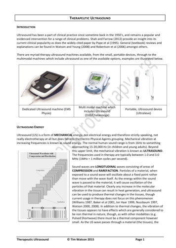
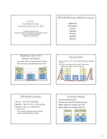
operating controlsULTRASOUND HEADONMTEMPI2TYCY E(O)100%50%20%CONTINUOUS PULSED 100 HzOUTPUT00030 -'···,5'/{ 025 ,,,'''I I20' 10It\'15MINUTES0CHATTAN .i?o !':-------------------1 . TREATMENT TIMER/ POWER SWITCH: This is a 0-29 minute rotary timer. When the timeris on, the green LED labeled Ultrasound On will be lit. When Timer is in the off position, power tothe generator is off.2. INTENSITY: Rotating this control knob clockwise increases the amount of ultrasound powerbeing delivered.3. HEAD MAX TEMP LED:This Red LED comes on when the temperature of the ultrasound head(transducer) reaches approximately 140 degrees F. At the time the LED comes on, the unit willstop producing ultrasound, the Ultrasound On LED will go out, and the Treatment Timer willcontinue to run. When the transducer cools to approximately 1 20 F, the LED will go off and theultrasound power will be restored.4. ULTRASOUND ON LED: This Green LED is on when ultrasound power is being transmitted fromthe transducer (sound head). This LED comes on when the Treatment Timer/Power Switch isfirst turned on.5. 20% PULSED SWITCH:By pressing this switch, the operator can select an ultrasound outputof 1 MHz that is pulsed at 1 00 pulses per second. This produces rectangular pulses of 2milliseconds duration, with an off time of 8 milliseconds between pulses.6. 50% PULSED SWITCH:By pressing this switch, the operator can select an ultrasound outputof 1 MHz that is pulsed at 1 00 pulses per second. This produces rectangular pulses of 5milliseconds duration, with an off time of 5 milliseconds between pulses.7. 100% CONTINUOUS SWITCH:By pressing this switch, the operator can select an ultrasoundoutput that is a continuous sinusodial waveform at a frequency of 1 MHz nominal.8. ULTRASOUND OUTPUT DISPLAY: This display shows the amount of ultrasound power andintensity available at the transducer (sound head). The upper scale is calibrated in Watts and thelower scale in W/CM2. Average power is shown when in continuous (1 00%1 mode. Peak power isshown when in pulsed 50%, 20%1 mode.6
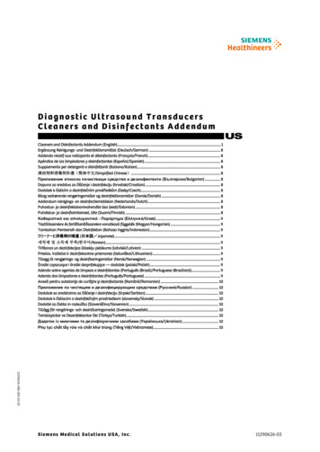
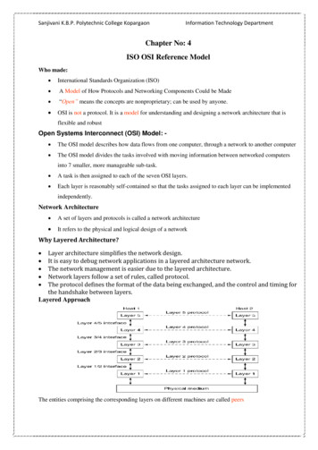
operating procedure1 . Plug the unit into a properly grounded outlet of the proper voltage and line frequency. Refer to the Nameplate on the rear of the unit.2. Operator should adjust the applicator handle to the desired position. Tighten thethumbscrew securely.3. Set the Treatment Timer at the 0 (Qffl position, and the Intensity control at the(fully counter clockwise position).4. At this point you may begin the treatment by applying lntelect Ultrasound Gel to thearea of the patient to be treated.5. Turn the Treatment Timer knob to the desired treatment time by turning the knobbeyond the desired time and then backing up to the desired time.6. Select the operating mode by pressing the appropriate switch. Switch 5 for the20% Pulsed Mode, Switch 6 for the 50% Pulsed Mode, or Switch 7 for the 100%Continuous Mode. The 20% Pulsed Mode is automatically selected upon actuationof the timer.7. You should then place the applicator in contact with the patient's body with a firmuniform pressure. You must keep the applicator moving during the treatment.Failure to keep the applicator moving may result in hazardous exposure to theultrasound energy.8. Adjust the Ultrasound Output by turning the Intensity control (2) until you reach thedesired output. Use the Upper scale for Watts and Lower scale forW/Cm2.9. If you need to interrupt the treatment for any reason, turn the Treatment Timer tothe off position (Bell will ringl. To resume treatment repeat steps 4-8.1 0. At the end of the treatment, the end of treatment bell will sound and the unit willshut off.in 230PINTENSITY TREATMENTTIMERPOWER IN WATTS510IOIN MAXITE(O)MP 30,@·'···.ULTRASOUND HEAD''f'tl 'f' s20o . 'I"'·ii:rlpe::.t;,.2s.1.s 11.52240-OUTPUT00. 2.1INTENSITY IN W/CM20,OUTY CYCLEt00100%10%10%CONnNUOUS PULUO 100 HzIEli El- .s-c · -1 :25":.,50,, 10,·''' ' , ''· UTE;CHATTANOOGAc ,.,.
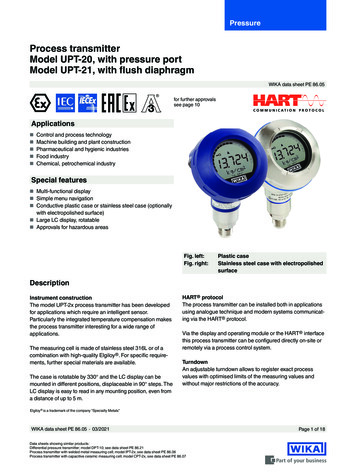
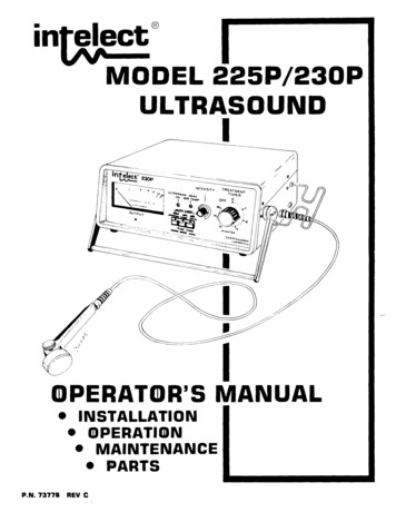
description of ultrasonic fieldThe spatial distribution of the radiated field is essentially a collimated beam of ultrasonic energyhaving a cross-sectional area of 8.5 CM2 for the 10 CM2 sound head when measured at a point 5millimeters from the transducer face.The energy distribution within the radiated field is 2.4 W/CM2 maximum, and takes a generally conicshape having decreasing intensity at progressively increasing distance from the face of thetransducer.This field distribution applies for the radiation emitted into the equivalent of an infinite medium ofdistilled degassed water at 30 deg. C. and with line voltage variations in the range of 1 0 percent ofthe rated line voltage. The ultrasonic field spatial distribution of the 5 CM 2 sound head is essentiallythe same as the field of the 10 CM2 sound head.PLOT OF ULTRASONIC FIELD SPATIAL DISTRIBUTION10 CM2I I1 v""1\90 /o80 /ot \j70 /oI&Oo/o\ 150 /o\' ,. /"80 /oEN40 /o\/'\ .0F20 /o10 /oE201001020RADIAL DISTANCE FROM CENTER OF APPUCATOA HEADMIWMETEAS8Tp030 /o )cSOo/o\J20 /o90 /o60 /o'I30 /o100 /o70 /ou \ .l40 /o10 /o,,vpEAwA
PLOT OF ULTRASONIC FIELD SPATIAL DISTRIBUTION5 CM 2v v ' .,100o/o 90 /o80 /o 70 /o\40 /oI\\I20 /o10 /o0 /o70 /o1\I30 /o80 /o60 {:,Ij50 /o90 /o\'IIfl"&Oo/o100 /o- 20'10010F30 /op010 /oQo/o20The following abbreviations are used on the applicator heads of the lntelect 225P/230P.BNR Beam Non-Uniformity RatioFreq. Frequency9ENT40 /oabbreviationsCall. Collimatingc0RADIAL DISTANCE FROM CENTER OF APPLICATOR HEADMILLIMETERSArea Effective Radiating AreaR50 /o20 /o pEwER
trouble shootingThe following problems and solutions are presented to assist you in solving some of theroblems that could possibly happen to your lntelect 225P o
The specifications put forth in this manual were in effect at the time of publication. However. owing to Chattanooga Corporation's policy of continuous improvement, changes to these specifications may be made at any time without obligation on the part of Chattanooga Corporation. · full one year warranty Chattanooga Corporation ("Company") warrants that lntelect Model 225P/230P ("Product") is .