Transcription
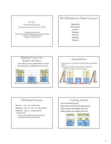
Sanjivani K.B.P. Polytechnic College KopargaonInformation Technology DepartmentChapter No: 4ISO OSI Reference ModelWho made: International Standards Organization (ISO) A Model of How Protocols and Networking Components Could be Made “Open” means the concepts are nonproprietary; can be used by anyone. OSI is not a protocol. It is a model for understanding and designing a network architecture that isflexible and robustOpen Systems Interconnect (OSI) Model: The OSI model describes how data flows from one computer, through a network to another computer The OSI model divides the tasks involved with moving information between networked computersinto 7 smaller, more manageable sub-task. A task is then assigned to each of the seven OSI layers. Each layer is reasonably self-contained so that the tasks assigned to each layer can be implementedindependently.Network Architecture A set of layers and protocols is called a network architecture It refers to the physical and logical design of a networkWhy Layered Architecture? Layer architecture simplifies the network design.It is easy to debug network applications in a layered architecture network.The network management is easier due to the layered architecture.Network layers follow a set of rules, called protocol.The protocol defines the format of the data being exchanged, and the control and timing forthe handshake between layers.Layered ApproachThe entities comprising the corresponding layers on different machines are called peers
Sanjivani K.B.P. Polytechnic College KopargaonInformation Technology Department It is the peers that communicate by using the protocols Actually, data is not transferred from layer n on one machine to layer n on another machine Each layer passes data and control information to the layer immediately below it, until the lowestlayer is reached Actual data communication takes place through the lowest layer – the physical layerDesign Issues for the Layers Addressing Error control Order of messages must be preserved Flow control – fast sender and slow receiver! Disassembling, transmitting, and reassembling large messages Multiplexing / de-multiplexing RoutingConcept of Services and Protocols: A service is a set of operations that a layer provides to the layer above it Service defines what operations the layer is prepared to perform A service relates to the interface between two layers – the lower layer is service provider and theupper layer is service userConcept of Services and Protocols A protocol is a set of rules governing the format and meaning of the packets Protocols relate to packets sent between peer entities on different machines Entities use protocols Protocols can be changed provided the services visible to the user do not change. Thus services andprotocols are completely decoupledServices and Protocols Analogy with programming languages A service is like an object in an object oriented language What operations can be performed on this object is defined How these operations are to be performed is not defined Protocol relates to the implementation of the service – how it is doneThe Layers of the OSI Model
Sanjivani K.B.P. Polytechnic College KopargaonInformation Technology DepartmentUserPhysical layer: Specifications for the physical components of the network.Functions of Physical Layer: Bit representation – encode bits into electrical or optical signalsTransmission rate – The number of bits sent each secondPhysical characteristics of transmission mediaSynchronizing the sender and receiver clocksTransmission mode – simplex, half-duplex, full duplexPhysical Topology – how devices are connected – ring, star, mesh, bus topology
Sanjivani K.B.P. Polytechnic College KopargaonInformation Technology DepartmentData Link Layer Data link layer attempts to provide reliable communication over the physical layer interface.Breaks the outgoing data into frames and re-assemble the received frames.Create and detect frame boundaries.Handle errors by implementing an acknowledgement and retransmission scheme.Implement flow control.The data link layer is responsible for moving frames from one hop (node) to the next.Functions of Data Link Layer Framing Divides the stream of bits into manageable data units called frames. Physical addressing Adds a header to the frame to define the sender and/or receiver of the frame. Flow control Imposes a flow control mechanism to avoid overwhelming the receiver.Synchronization between fast sender and slow receiver. Error control Adds mechanisms to detect and retransmit damaged or lost frames (CRC). Access control Determine which device has control over the link at any given time. Link establishment and termination: Establishes and terminates the logical link between two nodes. Frame sequencing: Transmits/receives frames sequentially. Frame acknowledgment: Provides/expects frame acknowledgments.DLL is divided into two Sub-Layers LLC Sub LayerMAC Sub Layer
Sanjivani K.B.P. Polytechnic College KopargaonInformation Technology DepartmentLogical Link Control Sub Layer It is upper portion of the Data Link layer. Performs Flow control and management of connection errors. LLC supports three types of connections:1. Unacknowledged connectionless service: does not perform reliability checks or maintain a connection, very fast, mostcommonly used2. Connection oriented service: once the connection is established, blocks of data can be transferred betweennodes until one of the node terminates the connection.3. Acknowledged connectionless service: provides a mechanism through which individual frames can be acknowledged.Media Access Control Sub Layer This sub layer contains methods to regulate the timing of data signals and eliminatecollisions. The MAC sub layer determines where one frame of data ends and the next one starts frame synchronization. There are four means of frame synchronization: Time based,Character counting,Byte stuffing andBit stuffing.Network Layer:Main functions of this layer are: Responsible for delivery of packets across multiple networks Routing – Provide mechanisms to transmit data over independent networks that are linked together. Network layer is responsible only for delivery of individual packets and it does not recognize anyrelationship between those packets
Sanjivani K.B.P. Polytechnic College KopargaonInformation Technology DepartmentTransport Layer:Main functions of this layer are: Responsible for source-to destination delivery of the entire message Segmentation and reassembly – divide message into smaller segments, number them and transmit.Reassemble these messages at the receiving end. Error control – make sure that the entire message arrives without errors – else retransmit.Session Layer:Main functions of this layer are: Dialog control – allows two systems to enter into a dialog, keep a track of whose turn it is to transmit Synchronization – adds check points (synchronization points) into stream of data.Presentation Layer:Responsibilities of this layer are: Translation Different computers use different encoding systems (bit order translation) Convert data into a common format before transmitting. Syntax represents info such as character codes - how many bits to represent data – 8 or 7 bits Compression – reduce number of bits to be transmitted Encryption – transform data into anunintelligible format at the sending end for data security Decryption – at the receiving end
Sanjivani K.B.P. Polytechnic College KopargaonInformation Technology DepartmentApplication Layer: Contains protocols that allow the users to access the network (FTP, HTTP, SMTP, etc) Does not include application programs such as email, browsers, word processing applications, etc. Protocols contain utilities and network-based services that support email via SMTP, Internet access viaHTTP, file transfer via FTP, etcData Encapsulation The outgoing information will travel down through the layers to the lowest layer. While moving down on the source machine, it acquires all the control informationwhich is required to reach the destination machine. The control information is in the form of Headers and Trailer which surrounds the datareceived from the layer above. This process of adding headers and trailers to the data is called as data encapsulation.
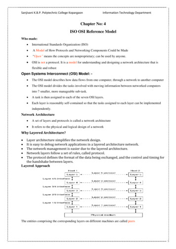
Sanjivani K.B.P. Polytechnic College KopargaonInformation Technology Department The information added by each layer is in the form of headers or trailers. At layer 1 the entire package is converted to a form that can be transferred to thereceiving machine. At the receiving machine, the message is unwrapped layer by layer, with eachprocess receiving and removing the data meant for it. For example, layer 2 removes the data meant for it, then passes the rest to layer 3. Layer 3 then removes the data meant for it and passes the rest to layer 4, and so on. The headers and trailers contain control information. The headers and trailers form theenvelope which carries the message to the desired destination.Figure: Data Encapsulation D7 means the data unit at layer 7, D6 means the data unit at layer 6, and so on. The process starts at layer 7 (the application layer), then moves from layer to layer indescending, sequential order. At each layer, a header, or possibly a trailer, can be added to the data unit. Commonly, the trailer is added only at layer 2. When the formatted data unit passes through the physical layer (layer 1), it is changedinto an electromagnetic signal and transported along a physical link.Example of Data EncapsulationThe figure shows the example of five layer stack for data encapsulation. The fifth layer of sending machine wants to send a message M to the fifth layer ofdestination machine.The message M is produced by layer 5 of machine 1 and given to layer 4 for transmission.Layer 4 adds header H4 in front of the message and pass it to layer 3.
Sanjivani K.B.P. Polytechnic College Kopargaon Information Technology DepartmentLayer 3 breaks up the incoming message into small units as M1 and M2 and pass thesepackets to layer 2.Layer 2 adds the header as well as footer to each packet obtained from layer 3 and pass itto layer 1 for physical transmission.Horizontal communication1. The horizontal communication is the logical connection between the layers, there is nodirect communication between them.2. Information included in each protocol header by the transmitting system is a messagethat will be carried to the same protocol in the destination system.3. For two computers to communicate over a n/w, the protocol used at each layer of theOSI model in the transmitting system must be duplicated at the receiving system.4. The packet travels up through the protocol stack and each successive header is strippedof by the appropriate protocol & processed.5. When the packet arrived at its destination, the process by which the headers areapplied at the source is repeated in server.
Sanjivani K.B.P. Polytechnic College KopargaonInformation Technology DepartmentVertical communication:1. In addition to communicating horizontally with the same protocol in the other system,the header information also enables each layer to communicate with the layer above &below it.Eg. The n/w layer will communicate with the data link layer & transport layer.2. This interlayer communication is called communication vertical.3. When a system receives a packet & passes it up through various layers the data linklayer protocol header includes a field which specifies the name of n/w layer protocol tobe used to process the packet.4. The n/w layer protocol header will specify the name of transport layer protocol to beused to process the packet.5. Due to vertical communication, it becomes protocol at each layer simultaneously.Fig: Vertical communicationError Detection and Correction Networks must be able to transfer data from one device to another with completeaccuracy. Data can be corrupted during transmission. For reliable communication, errors must be detected and corrected. Error detection and correction are implemented either at the data link layer or thetransport layer of the OSI model.Definition of ErrorNetworks must be able to transform data from once device to another with complete accuracy.While the transmission data can be corrupted, for reliable communication errors must bedetected and corrected.
Sanjivani K.B.P. Polytechnic College KopargaonInformation Technology DepartmentTypes of ErrorsSingle-bit errors In a single-bit error, only 1 bit in the data unit has changed from either 0 to 1 or 1 to 0.Single bit errors are the least likely type of errors in serial data transmission becausethe noise must have a very short duration which is very rare. However this kind oferrors can happen in parallel transmission.Example:o If data is sent at 1Mbps then each bit lasts only 1/1,000,000 sec. or 1 μs.o For a single-bit error to occur, the noise must have a duration of only 1 μs, whichis very rare.Multiple-bit errors A multi bit error means that 2 or more bits in the data unit have changedBurst errors A burst error means that 2 or more consecutive bits in the data unit have changed.The term burst error means that two or more bits in the data unit have changed from 1to 0 or from 0 to 1.Burst errors does not necessarily mean that the errors occur in consecutive bits,the length of the burst is measured from the first corrupted bit to the last corrupted bit.Some bits in between may not have been corrupted.
Sanjivani K.B.P. Polytechnic College KopargaonInformation Technology Department Burst error is most likely to happen in serial transmission since the duration of noise isnormally longer than the duration of a bit. The number of bits affected depends on the data rate and duration of noise.Example: If data is sent at rate 1Kbps then a noise of 1/100 sec can affect 10 bits.(1/100*1000) If same data is sent at rate 1Mbps then a noise of 1/100 sec can affect 10,000b
It is a model for understanding and designing a network architecture that is flexible and robust Open Systems Interconnect (OSI) Model: - The OSI model describes how data flows from one computer, through a network to another computer The OSI model divides the tasks involved with moving information between networked computers