Transcription
505 Gillingham LaneSugar Land, TX 77478O: (281) 325-8300F: (281) 325-8399E: aservice@laversab.comMODEL 6600-NGUSER'S MANUALDate: May 12, 2017.Document Number: 125-9110A
6600-NG User’s ManualWARRANTYLaversab Inc., warrants its products to conform to or exceed the specifications as set forth in its catalogs inuse at the time of sale and reserves the right, at its own discretion, without notice and without making similarchanges in articles previously manufactured, to make changes in materials, designs, finish, or specifications.Laversab Inc. warrants products of its own factory against defects of material or workmanship for a period ofone year from date of sale.Liability of Laversab Inc. under this warranty shall be limited to replacing, free of charge (FOB Houston,Texas), any such parts proving defective within the period of this warranty, but Laversab Inc. will not beresponsible for transportation charges, consequential or incidental damages. No liability is assumed byLaversab for damages that are caused by misuse or abuse of the product.The warranty of Laversab Inc. is not made for products manufactured by others which are illustrated anddescribed in Laversab catalogs or incorporated in Laversab products in essentially the same form as suppliedby the original manufacturer. Warranties of the original manufacturers supplant the warranty of LaversabInc., but, in applicable instances, the latter agrees to use its best efforts to have original suppliers make goodtheir warranties.COPYRIGHT NOTICECopyright (c) 2017 by Laversab Inc. All rights reserved. The content of this manual may not be reproducedin any form by any means, in part or in whole, without the prior written permission of Laversab Inc.DISCLAIMERNo representations or warranties are made with respect to the contents of this user's manual. Further,Laversab Inc. reserves the right to revise this manual and to make changes from time to time in the contenthereof without obligation to notify any person of such revision.125-9110APage 2
6600-NG User’s ManualREVISION HISTORYDocument No.Release DateDescription125-9110A05/12/20176600-NG User’s Manual, Rev A125-9110APage 3
6600-NG User’s ManualWARNINGTHE 6600-NG USES LINE VOLTAGES FOR ITS OPERATION WHICH ARE POTENTIALLYDANGEROUS. IMPROPER OPERATION OF THIS EQUIPMENT MAY RESULT IN PERSONAL INJURYOR LOSS OF LIFE. HENCE THE EQUIPMENT DESCRIBED IN THIS MANUAL SHOULD BE OPERATEDONLY BY PERSONNEL TRAINED IN PROCEDURES THAT WILL ASSURE SAFETY TO THEMSELVES,TO OTHERS AND TO THE EQUIPMENT.BEFORE PERFORMING ANY MAINTENANCE, TURN THE POWER OFF AND DISCONNECT THEPOWER CORD FROM THE POWER SOURCE.ALWAYS USE A 3-PIN GROUNDED OUTLET AS YOUR AC POWER SOURCE125-9110APage 4
6600-NG User’s ManualTABLE OF CONTENTSWARRANTY. 2COPYRIGHT NOTICE . 2DISCLAIMER . 2REVISION HISTORY. 3WARNING . 4SECTION 1 : INTRODUCTION . 7SECTION 2 : CONTROLS & CONNECTIONS. 82.1MAIN UNIT, TOP PANEL . 82.2REMOTE UNIT . 13SECTION 3 : OPERATING THE 6600-NG . 163.1START-UP . 163.2MAIN OPERATING SCREEN . 173.3CHANGING UNITS . 273.4CHANGING TARGET VALUES . 313.5CHANGING RATE TARGET VALUES . 363.6CHANGING MODES . 423.6.1MEASURE TO CONTROL TRANSITION . 463.6.2LEAK CHECKS . 463.7SELF-TEST FUNCTION . 523.8GO-TO-GROUND FUNCTION . 533.9HOLD FUNCTION . 543.10OTHER FUNCTIONS . 543.10.1VIEW LIMITS . 553.10.2MODIFY LIMITS . 553.10.3ADJUST DISPLAY BRIGHTNESS . 573.10.4RUN PROFILE . 573.10.5LOAD PROFILE . 613.10.6HEIGHT CORRECTION . 613.10.7SET LEAK TIMERS . 623.10.8CALIBRATION (PRELIMINARY). 633.10.9ENCODER. 643.11INTERNAL-BATTERY OPERATION . 653.12LEAK-CHECKING THE 6600-NG . 66SECTION 4 : PROFILES . 67125-9110APage 5
6600-NG User’s Manual4.1WHAT IS A PROFILE . 674.2CREATING A PROFILE. 694.3SETTING UP HYPERTERMINAL . 714.4LOADING PROFILES . 714.5RUNNING A PROFILE. 72SECTION 5 : TYPICAL USE . 73SECTION 6 : CALIBRATION . 756.1EQUIPMENT. 756.26600-NG TRANSDUCERS . 756.3SETUP OF 6600-NG . 756.4CALIBRATION PROCEDURE. 776.5VERIFICATION PROCEDURE . 80SECTION 7 : MAINTENANCE. 84SECTION 8 : RS232 SERIAL INTERFACE . 858.1COMMUNICATION SETUP. 858.2COMMUNICATION PROTOCOL & COMMANDS . 85APPENDIX A : ERROR CODES . 94APPENDIX B : SPECIFICATIONS . 95APPENDIX C : CONNECTOR PIN-OUTS. 97APPENDIX D : REPAIR & RETURN POLICIES . 98APPENDIX E : WI-FI OPERATION . 99125-9110APage 6
6600-NG User’s ManualSECTION 1 : INTRODUCTIONThe model 6600-NG is a high accuracy automated pressure controller, with three independent pressureoutputs, specifically designed for controlling air data parameters such as altitude, airspeed, Mach and climb.The three independent outputs of Pt, Ps2 and Ps1 makes the 6600-NG ideal for testing aircraft with AOA/AOS probes. This instrument can also be used to control pressures in units of inHg, mbar, psi, mmHg andkpa. The 6600-NG is equipped with internal pressure and vacuum pumps. The Remote unit is used tointerface with the Main unit. The small size of the Remote unit allows it to be used in the cockpit of anaircraft.The 6600-NG has three high accuracy transducers that measure pressure in the range of 1 to 42 inHg absoluteon the Ps1 and Ps2 outputs, and 0 to 30 inHg differential on the Pt output. These transducers are designed toaccurately measure the pressure of dry air over an ambient temperature range of -40oC to 80oC. The highaccuracy of the Ps1 and Ps2 transducers makes the 6600-NG fully RVSM compliant.The 6600-NG allows the user to control altitude in feet or meters, climb in feet per minute or meters persecond. Airspeed can be controlled in knots, mach, km/hr and mph. Airspeed-rate can be also be controlledin these units. The 6600-NG also allows the user to control EPR on the Pt output.The model 6600-NG features programmable limits on altitude, airspeed, airspeed rate, mach number, climbrate and Differential pressure (between Ps2 and Ps1). These limits are checked during data entry and therebyprohibit entry of erroneous target values. These limits are also checked continuously during operation, and ifany of these is exceeded, the unit automatically takes abortive action.The user has the ability to program into the 6600-NG a profile of set-points to be controlled in a sequence.Once such a profile has been setup, the user can command the unit to move from one set-point to the nextsimply by using the Up-arrow key. Up to 50 points can be stored in one profile. The 6600-NG can store up to10 such profiles in non-volatile memory at any one time.Calibration of the unit is required only once a year. This process is the only scheduled maintenance functionrequired on the 6600-NG.The standard version of the model 6600-NG operates on AC power and comes with an RS232 interface.Options include an internal battery which lasts up to 8 hours, internal heaters which allow the unit to operatedown to -40oC, and an altimeter-encoder interface.The 6600-NG has built-in Wi-Fi capability which allows for wireless remote operation using an iPad.125-9110APage 7
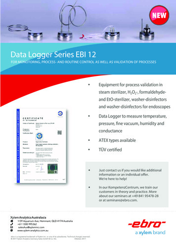
6600-NG User’s ManualSECTION 2 : CONTROLS & CONNECTIONS2.1MAIN UNIT, TOP PANELThe model 6600-NG top panel provides easy access to all the connections. Please refer to Figure 2.1. (shownon next page)[1]AC INPUT connector :This is a 3-pin male circular connector. A power cord is provided with the 6600-NG. The circular connectorend of the power cord needs to be connected here. The power requirement of the 6600-NG is 90-260 VAC,47-440 Hz with a maximum power consumption of 100 VA (200 VA with heaters). The pin-out of thisconnector is provided in Appendix CCaution: Connecting incorrect power to the 6600-NG will cause considerable damage[2]AC Fuse :A 5x20 mm fuse is located inside the fuse holder. This time-delay fuse, with a rating of 2.0 amps, 250 Volts,limits AC power to the unit.[3]AC On/Off switch :This toggle switch connects (or disconnects) AC power between the AC INPUT connector and the 6600-NG.Even when this switch is ON, the 6600-NG becomes fully operational only after the Power key located on thekeypad of the Remote Unit is pressed for a minimum of 3 seconds.When an integrated battery is included, the battery-charging circuits inside the 6600-NG become active whenthe AC On/Off switch is turned ON.When internal heaters are included, the heater-control circuits inside the 6600-NG become active when theAC On/Off switch is turned ON.[4]Battery Fuse :This fuse is installed only if an integrated battery is included. A 5x20 mm fuse is located inside the fuseholder. This time-delay fuse, with a rating of 10 amps, 250 Volts, limits Battery power to the unit.125-9110APage 8
31119196191920141517187813912541610126600-NG User’s ManualFigure 2.1 : 6600-NG Top Panel125-9110APage 9
6600-NG User’s Manual[5]Battery On/Off switch:This switch is installed only if an integrated battery is included. This switch connects (or disconnects) thebattery from other circuits within the 6600-NG. If AC power is not available, turning this switch On allowsthe unit to operate on battery-power.In situations where AC power may be intermittent, it is advisable to keep the Battery On/Off switch in theOn position. This will allow the internal circuits to automatically switch to battery power when AC power islost.Caution: When the unit is not being used, the Battery On/Off switch must be in the Off position.Leaving this switch On will drain the battery since some internal circuits will be active when this switchis On.[6]Remote Unit connection:Using the 30-foot remote cable, connect the Remote unit to the Main unit through this 10-pin circularconnector. It is recommended that this connection be made prior to applying power to the 6600-NG. If thiscable is disconnected, the 6600-NG will stop operating.[7]Emergency Vent Valve, "Pt Cross-bleed" :In the event that the 6600-NG is in-operable due to a malfunction or due to loss of power, it is possible to ventthe Pt system manually. This is done using the metering valve labeled “Pt Cross-bleed”. This valve is apositive shut-off valve. Opening this valve slowly will equalize the pressure between the Pt and Ps1 systems(causing airspeed to be at zero).Since opening this valve transfers pressure from the Pt system into the Ps1 system of the aircraft, whileopening this valve, care must be taken to vent the Ps1 system simultaneously (if necessary), to prevent thealtimeter in the aircraft from going below (minus) -1000 feet. Also, care must be taken not to exceed themaximum value of the Climb indicator in the aircraft.Once airspeed is down to zero, this valve must be opened completely, to ensure that airspeed stays at zerowhile the Ps1 system is vented to ambient (using the “Ps1 Vent” valve).Caution: This valve is for emergency use only and should not be used during normal operation. Whenemergency venting is completed, this valve should be closed immediately.Caution: This valve should not be tightened at all past its stop. It seals before it hits the stop. Evenfinger-tight beyond the stop may damage the seat of the valve, causing it to leak constantly.[8]Emergency Vent Valve, "Ps2 Cross-bleed" :125-9110APage 10
6600-NG User’s ManualIn the event that the 6600-NG is in-operable due to a malfunction or due to loss of power, it is possible to ventthe Ps2 system manually. This is done using the metering valve labeled “Ps2 Cross-bleed”. This valve is apositive shut-off valve. Opening this valve slowly will equalize the pressure between the Ps2 and Ps1systems (causing the differential between Ps1 and Ps2 to be at zero).Since opening this valve transfers pressure from the Ps2 system into the Ps1 system of the aircraft, whileopening this valve, care must be taken to vent the Ps1 system simultaneously (if necessary), to prevent thealtimeter in the aircraft from going below (minus) -1000 feet. Also, care must be taken not to exceed themaximum value of the Climb indicator in the aircraft.Once Ps2 pressure is almost equal to Ps1 pressure, this valve must be opened completely, to ensure that thedifferential stays near zero while the Ps1 system is vented to ambient (using the “Ps1 Vent” valve).Caution: This valve is for emergency use only and should not be used during normal operation. Whenemergency venting is completed, this valve should be closed immediately.Caution: This valve should not be tightened at all past its stop. It seals before it hits the stop. Evenfinger-tight beyond the stop may damage the seat of the valve, causing it to leak constantly.[9]Emergency Vent-Valve, “Ps1 Vent”:In the event that the 6600-NG is in-operable due to a malfunction or due to loss of power, it is possible to ventthe Ps1 system manually. This is done using the metering valve labeled “Ps1 Vent”. This valve is a positiveshut-off valve. Opening this valve slowly will vent the Ps1 output of the 6600-NG to ambient pressure.While venting, care must be taken not to exceed the maximum value of the Climb indicator in the aircraft.Also, before venting the Ps1 system to ambient, the “Pt Cross-bleed” and “Ps2 Cross-bleed” valves must beopened completely to ensure that airspeed is zero and there is no differential pressure on Ps2.Caution: This valve is for emergency use only and should not be used during normal operation. Whenemergency venting is completed, this valve should be closed immediately.Caution: This valve should not be tightened at all past its stop. It seals before it hits the stop. Evenfinger-tight beyond the stop may damage the seat of the valve, causing it to leak constantly.[10]Ps1 port :The Ps1 port of the tester is provided with a #4-AN fitting. This port must be connected through a hose tothe Ps1 port of the aircraft. The hose must be connected after performing the Self Test on the 6600-NG. Thehose, once connected, must not be disconnected while the aircraft Ps1 system is not at “Ground” level.Caution: Do not connect the Ps1 hose to the Ps1 port before performing the Self Test.125-9110APage 11
6600-NG User’s ManualCaution: Do not disconnect the Ps1 hose from the Ps1 port unless the aircraft Ps1 system is at “Ground”level and the tester has been turned Off.[11]Ps2 port :The Ps2 port of the tester is provided with a #4-AN fitting. This port must be connected through a hose tothe Ps2 port of the aircraft. The hose must be connected after performing the Self Test on the 6600-NG. Thehose, once connected, must not be disconnected while the aircraft Ps2 system is not at “Ground” level.Caution: If the Ps2 port is not being used, it must be capped and Ps2 units must be in “Dfin” with the Ps2Target value set to 0.0000 inHg (Dfin) .Caution: Do not connect the Ps2 hose to the Ps2 port before performing the Self Test.Caution: Do not disconnect the Ps2 hose from the Ps2 port unless the aircraft Ps2 system is at “Ground”level and the tester has been turned Off.[12]Pt port :The Pt port of the tester is provided with a #4-AN fitting. This port must be connected through a hose to thePt port of the aircraft. The hose must be connected after performing the Self Test on the 6600-NG. The hose,once connected, must not be disconnected while the aircraft Pt system is not at “Ground” level.Caution: Do not connect the Pt hose to the Pt port before performing the Self Test.Caution: Do not disconnect the Pt hose from the Pt port unless the aircraft Pt system is at “Ground” leveland the the tester has been turned Off.[13]Indicator LED’s :‘Ready’ LED: This green LED provides several indications as described below.a.When the unit is ready for use, the LED is steadily On.b.When the Remote is not connected, the LED blinks two times every 2-secondsc.When the temperature is too low for operation (on units without heaters), the LED blinks once every2-seconds.d. After the unit is ready for use, when the Power key on the Remote is pressed, the LED blinks rapidlywhile the Power key is held down. If the Power key is held down for more than 3 seconds, either aturn-On or Turn-Off condition is ‘detected’ and the LED blinks slowly for 5 more seconds, duringwhich the user must release the Power key.‘Heaters’ LED: On units equipped with internal heaters, this yellow LED will turn On while the heaters areOn. The LED may stay On even after the Ready LED comes On.125-9110APage 12
6600-NG User’s Manual‘Low-Batt’ LED: On units with an internal battery, this yellow LED will turn On when a low-batterycondition is detected. After this LED turns On, the user will typically have 15 to 20 minutes before the unitautomatically turns Off due to total discharge of the battery. The Remote unit also displays a low-batterycondition as a warning message.‘Charging’ LED: On units with an internal battery, this red LED will be On while the battery is beingcharged.[14]RS232 interface connector:This connector is accessed by opening the “Interface Connectors” access panel.The connector is a standardDB-9 female connector used for a serial RS232 interface. It can be connected directly to the “COM” port of astandard PC to allow communication. This port is normally used for downloading “profiles” from acomputer. Other remote communication with the 6600-NG is also possible through this interface.For more details on downloading profiles, please refer to Section 4. For more details on communication withthe 6600-NG, please refer to Section 8. The pin-out of this connector is provided in Appendix C.[15]Encoder interface connector:This connector is accessed by opening the “Interface Connectors” access panel. If the Encoder option isincluded with the tester, this connector will interface to an altimeter encoder and enable the 10-bit Gray codeto be displayed on the Remote unit. For more details, please refer to Section 3.10.9. The pin-out of thisconnector is provided in Appendix C.[16]Earth Ground stud[17]Wi-Fi Antenna[18]Battery connector:If a removable battery is provided with the unit, connect the battery here.Caution:While connecting or disconnecting the integrated battery, make sure that the BatteryOn/Off switch is Off, the AC On/Off switch is Off and there is no AC power connected to the unit.[19]Battery mounting locations:If a removable battery is provided with the unit, the battery case is be mounted to the Top panel of theunit at these mounting points.[20]Remote Unit placement:During transportation, the Remote Unit is placed in this location.125-9110APage 13
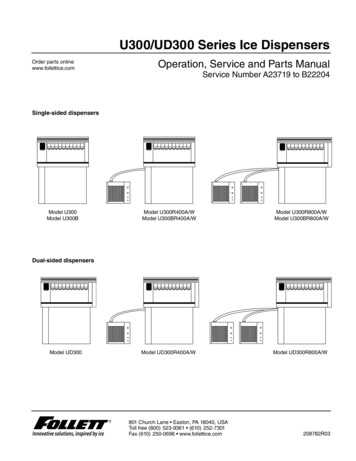
6600-NG User’s Manual2.2REMOTE UNIT123222Figure 2.2 : Remote UnitPlease refer to Figure 2.2 which shows the front-view of the Remote unit.[1]LCD Display:The Remote unit has a 5.8 inch Color TFT display with a resolution of 640 x 480 pixels. The backlight has amaximum brightness of 800 nits which makes the display sunlight-readable. The backlight brightness can beadjusted by the user through a function on the Remote. More details are provided in Section 3.10.3.[2]Keypad:Left section: This section of the keypad includes the following keys:TEST – Used to perform a Self-testFUNC – Allows selection of several functionsGND – Performs the “Go To Ground” operation.HOLD - Stops ramping to a set-point and holds outputs at current values.Up-Arrow – Used to jog a target-value up or move to next profile-point.125-9110APage 14
6600-NG User’s ManualDown-Arrow – Used to jog a target-value down or move to previous profile-point.Further details are provided in Section 3.Center section: This section of the keypad is used for numeric entry. To enter a negative value, enter thevalue and then press the ‘ /-‘ key. Use the ‘000’ key to enter three consecutive zeroes, which is especiallyuseful when entering numbers in thousands.Right section: This section has the ‘GO’ and ‘CANC’ keys which are used to either execute or exit/cancel acommand. The CANC key is also used to acknowledge messages.The Power key, indicated by thesymbol , is used to either turn-On or turn-Off the 6600-NG.When the Remote unit is Off and the Ready LED is On, pressing the Power key for 2 to 3 seconds will turnOn the 6600-NG. The display takes another 2 seconds to come on. The Power key may be held down untilthe display turns On (a total of about 4 seconds), but must be released within 2 to 3 seconds after the displayturns On (to avoid going into the Power-Off cycle).When the Remote unit is On, pressing the Power key for 3 seconds will turn the 6600-NG and the Remoteunit Off. After the unit turns Off, the Power key must be released within 2 to 3 seconds, to avoid going intothe Power-On cycle.[3]Connector:This circular connector is used to connect the Remote unit to the Main unit through the Remote cable. TheRemote unit must not be disconnected from the Main unit while the unit is operating. This will cause theunit to turn Off.[4]Tilt-stand:On the rear of the Remote unit, a tilt-stand has been provided which allows the Remote to be tilted to aconvenient viewing angle.125-9110APage 15
6600-NG User’s ManualSECTION 3 : OPERATING THE 6600-NGThis section provides all the details required to operate the 6600-NG. It is highly recommended that theuser read through this section before operating the 6600-NG. After understanding these details, the usershould refer to the ‘Typical Use’ chart shown in Figure 5.1, which outlines a step-by-step process of usingthe 6600-NG with an aircraft.3.1START-UP Open the Pt, Ps2 and Ps1 ports to ambient by removing the blue caps. Connect the Remote unit to the Main unit using the Remote cable. Connect AC power to the Main unit using the power cable. Turn On the AC On/Off switch on the Top Panel of the Main unit. Wait for the Ready LED to turn On. Press the Power key on the Remote for about 4 seconds until the display turns On. Release the Power key. After the sign-on screen, the display will appear similar to that shown inFigure 3.1 (next page).Note: The pumps will be Off. The pumps turn On only if one of the outputs is in either Control orLeak mode. The pumps also turn On during Self-Test. Perform a Self-Test by pressing the TEST key. The message ‘Open all 3 ports to ambient, then pressGO. Press CANC to exit’ will be displayed in the Lower section of the display. Make sure all 3 portsare open to ambient, then press GO. The Self-Test takes about 2 minutes. Status updates are shown in the lower section of the display.When it is completed, the message ‘Self-Test successful. Press CANC to exit’ will appear on the lastline. Press CANC.The following sub-section provides details of the parameters shown on the main operating screen andhow to modify these parameters.Later sub-sections provide details on how to perform various other functions of the 6600-NG125-9110APage 16
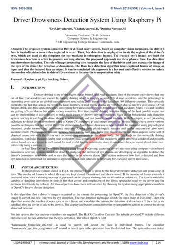
6600-NG User’s 000inHg/mininHg/mininHg/min0.0000.0000.000Pt 000764Measure MeasureMeasure87000 Hide/Show Ps2MessagesAC92%121314Figure 3.1 : Main operating screen (partial details)3.2MAIN OPERATING SCREENPlease refer to Figure 3.1. There are 16 different items (indicated in red) shown on this screen. Numbers1 to 7 on the left side, refer to the Pt-output parameters. Numbers 8 to 14 on the right side, refer to thePs1-output parameters. Numbers 15 and 16 point to a typical symbol indicating a key number (as shown,key # 1 and key # 5). Details of each item follow.[1]Pt unitsThe selected Pt units are displayed here. There are 15 different Pt units available.1.2.3.4.knotsMachkm/hrmph5.6.7.8.Pt inHgQc inHgPt mbarQc mbar9. Pt psi10. Qc psi11. Pt mmHg12. Qc mmHg13. Pt kpa14. Qc kpa15. EPRNote: Qc units display differential pressure with respect to Ps1 pressure. Pt units display absolute Ptpressure.Selecting the desired Pt units is described in Section 3.3.125-9110APage 17
6600-NG User’s Manual[2]Pt Actual valueThe Actual value (actual pressure converted to selected units) being measured or controlled at the Ptoutput is displayed here in the selected Pt units. The displayed resolution of this value depends on theselected units and is shown in the table below. This Actual value is updated every 250 msec.DisplayedResolutionPt unitsknots0.1Mach0.001km/hr0.1mph0.1Pt inHg0.0001Qc inHg0.0001Pt mbar0.01Qc mbar0.01Pt psi0.001Qc psi0.001Pt mmHg0.01Qc mmHg0.01Pt kpa0.001Qc kpa0.001EPR0.001Important Note: When Pt units are knots, km/hr or mph, and both ports are open to ambient, theActual airspeed value could be as high as /-8 knots (instead of the expected 0 knots). This is stillwithin the specified accuracy of /-0.003
505 Gillingham Lane Sugar Land, TX 77478 O: (281) 325-8300 F: (281) 325-8399 E: aservice@laversab.com Document Number: 125-9110A MODEL 6600-NG