Transcription
For U.S. and Canadian InstallationsMODELSRU199i (REU-N3237FF-US)RU180i (REU-N2934FF-US)RU160i (REU-N2530FF-US)RU130i (REU-N2024FF-US)CU199i (REU-N3237FFC-US)CU160i (REU-N2530FFC-US)RUR199i (REU-NP3237FF-US)RUR160i (REU-NP2530FF-US)CUSWARNINGIf the information in these instructions is not followed exactly, a fire or explosion may resultcausing property damage, personal injury or death.— Do not store or use gasoline or other flammable vapors and liquids in the vicinity of this or any other appliance.— WHAT TO DO IF YOU SMELL GAS Do not try to light any appliance. Do not touch any electrical switch; do not use any phone in your building. Immediately call your gas supplier from a neighbor’s phone. Follow the gas supplier’s instructions. If you cannot reach your gas supplier, call the fire department.— Installation and service must be performed by a licensed professional.PVC/CPVC Common Venting Installation InstructionsCopyright 2018 Rinnai America Corporation. All Rights Reserved.1100000625(01) 12/18CERTIFIED TO ANSI Z21.10.3 - CSA 4.3
ContentsWelcome .3Safety.4About the Common Venting System .5Venting Guidelines . 5Schedule 40 PVC/CPVC Common Vent Guidelines . 7High Altitude Installations . 8Common Vent Maximum Equivalent Lengths . 93 in. Common Venting . 103 in. Direct Vent and Room Air . 104 in. Common Venting . 114 in. Direct Vent and Room Air . 116 in. Common Venting . 126 in. Direct Vent and Room Air . 12Common Vent Terminations . 13Sample Horizontal Termination Assembly . 14Sample Vertical Termination Assembly-Room Air . 15Maintenance Clearances . 16Water Heater Clearances. 16Vertical Termination Clearances . 16Horizontal Termination Clearances . 17Combustion Air Requirements . 18Exhaust Vent Termination Clearances . 21Additional Clearances . 23Installation Instructions (Condensate Trap and Drain Pipe) . 24Final Checklist . 24READ AND SAVE THESE INSTRUCTIONSPVC/CPVC Common Venting Installation InstructionsCopyright 2018 Rinnai America Corporation. All Rights Reserved.2
WelcomeThis manual provides installation instructions for PVC/CPVC common venting and is a supplement to the Installationand Operations Manual supplied with the Rinnai Tankless Water Heater.Common venting must satisfy all the requirements of the Installation and Operations Manual, as well as therequirements in this manual.For detailed information on the Rinnai Tankless Water Heater, including installation instructions, refer to the TanklessWater Heater Installation and Operation Manual or view an online version at rinnai.us.To The Installer This manual is intended for the trained and qualified professional and is designed for licensed installers whoshould have skills such as: Gas sizing Connecting gas lines, water lines, valves, and electricity Knowledge of applicable national, state, and local codes Installing venting through a wall or roof Training in installation of tankless water heaters. Training on Rinnai Tankless Water Heaters isaccessible at www.trainingevents.rinnai.us A trained and qualified professional must test the Common Venting System for leaks before use. The installation must conform to the Rinnai Tankless Water Heater Installation and Operation Manual that isshipped with the unit, local codes, or in the absence of local codes, with the National Fuel Gas Code,ANSI Z223.1/NFPA 54. Read all instructions contained in this manual before installing the Common Venting System. Proper installation is the responsibility of the installer. When installation is complete, give all manuals related to the common venting installation (including thismanual and the Rinnai Tankless Water Heater Installation and Operation Manual) directly to theconsumer. The manuals should be stored in a readily accessible location for future reference.To The Consumer Keep this manual for future reference. Be sure your Common Venting System is installed by a trained and qualified professional.PVC/CPVC Common Venting Installation InstructionsCopyright 2018 Rinnai America Corporation. All Rights Reserved.3
SafetyTopics in this section Safety SymbolsREAD ALL INSTRUCTIONS BEFORE INSTALLATIONWARNING If the information in these instructions is not followed exactly, a fire or explosion may result causing propertydamage, personal injury, or death.Do not store or use gasoline or other flammable vapors and liquids in the vicinity of this or any other appliance.WHAT TO DO IF YOU SMELL GAS: Do not try to light any appliance. Do not touch any electrical switch; do not use any phone in your building. Immediately call your gas supplier from a neighbor’s phone. Follow the gas supplier’s instructions. If you cannot reach your gas supplier, call the fire department.Installation and service must be performed by a qualified installer, service agency or the gas supplier.The warning signs in this manual are here to prevent injury to you and others. Please follow them explicitly.Installations must comply with local requirements and with the National Fuel Gas Code, ANSI Z223.1/NFPA 54 forU.S. installations.Use only the materials listed in this manual for vent, air intake pipe, and fittings. Failure to comply with thiswarning could result in property damage.DO NOT slope the combustion air pipe toward unit. Failure to comply with this warning could result in propertydamage, personal injury, or death.DO NOT apply PVC/CPVC glues, solvents, or cleaners to the tankless water heater’s intake or exhaust gasketconnections. Failure to correctly assemble the components according to these instructions and the Rinnai waterheater installation and operation manual may result in property damage, personal injury, or death.Safety SymbolsThis manual contains the following important safety symbols. Always read and obey all safety messages.Safety alert symbol. Alerts you to potentialhazards that can kill or hurt you and others.DANGERIndicates an imminentlyhazardous situation which, ifnot avoided, will result inpersonal injury or death.PVC/CPVC Common Venting Installation InstructionsCopyright 2018 Rinnai America Corporation. All Rights Reserved.WARNINGIndicates a potentially hazardoussituation which, if not avoided, couldresult in personal injury or death.CAUTIONIndicates a potentially hazardoussituation which, if not avoided, couldresult in minor or moderate injury. Itmay also be used to alert againstunsafe practices.4
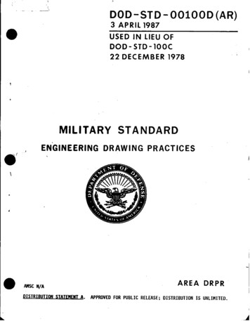
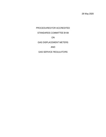
About the Common Venting SystemTopics in this section Venting GuidelinesSchedule 40 PVC/CPVC Common VentGuidelinesHigh Altitude InstallationsCommon Vent Maximum EquivalentVent LengthsCommon venting allows multiple Rinnai Tankless Water Heaters to share the same vent system.Rinnai Tankless Water Heaters can only be common vented with Schedule 40 PVC/CPVC or with a Rinnai certifiedcommon vent system.Example: Rinnai Common VentingExample: Schedule 40 PVC/CPVCCommon VentingVenting Guidelines Use only the materials listed in this manual for vent, air intake pipe, and fittings. Failure to comply with this warning could result in property damage, personal injury, or death.When cutting vent components, ensure that the cuts are straight.Chamfer and deburr all edges before installing the components.Vent joints must not leak. Confirm gas tight connections of every vent joint.Before operating the water heater(s), ensure vent system is clean and free of debris.Vent system must be supported according to the vent manufacturer’s installation instructions.Venting should be as direct as possible with a minimum number of fittings.The common vent system must only be installed by a trained and qualified professional.Common Vent Termination Clearances Vent termination per ANSI Z223.1/NFPA 54. For clearances not specified in ANSI Z223.1/NFPA 54,clearances are in accordance with local installation codes and the requirements of the gas supplier.PVC/CPVC Common Venting Installation InstructionsCopyright 2018 Rinnai America Corporation. All Rights Reserved.5
WARNINGDO NOT slope the combustion air pipe toward unit. Failure to comply with this warning could result in propertydamage, personal injury, or death.DO NOT apply PVC/CPVC glues, solvents, or cleaners to the tankless water heater’s intake or exhaust gasketconnections. Failure to correctly assemble the components according to these instructions may result in propertydamage, personal injury, or death.Do Not Do not exceed the maximum number of units indicated in the Rinnai Tankless Water Heater Installation andOperation Manual. Do not use cellular core PVC/CPVC, Radel, ABS or galvanized material for the exhaust vent. Do not combine vent components from different manufacturers. Do not connect the venting system with an existing vent or chimney. Do not cover vent components with thermal insulation. Do not common vent with the vent pipe of any other type of water heater or appliance. Do not reduce vent diameter to less than 2 in. (51 mm). Do not install the water heater in an area of negative pressure. Do not install the water heater, venting, and vent termination(s) in any areas where the air may containcorrosive compounds.Must Do You must use vent components that are certified and listed with the water heater model. The vent system must vent directly to the outside of the building and use outside air or room air forcombustion. Avoid dips or sags in horizontal vent runs by installing supports per the vent manufacturer’s instructions. Support horizontal vent runs a minimum of every four feet and all vertical vent runs a minimum of every sixfeet. Venting should be as direct as possible with a minimum number of pipe fittings. Vent components connected to the water heater must be secured with one self-tapping screw. Do not useany glues or solvents to connect vent components to the water heater. Set the temperature setting on all water heaters being common vented to the same temperature.PVC/CPVC Common Venting Installation InstructionsCopyright 2018 Rinnai America Corporation. All Rights Reserved.6
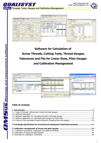
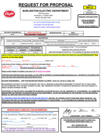
Schedule 40 PVC/CPVC Common Vent GuidelinesWARNING PVC solvents (primer and glue) can be extremely flammable. Vapors may cause a flash fire orexplosion resulting in property damage, personal injury or death.Keep solvents away from heat, sparks, flames and all other sources of ignition.Do not solder, cut or weld until all vapors have dissipated.PVC solvents are heavier than air causing them to settle at low points of the system.Before using PVC solvent: Disconnect power to the water heater. Remove the front cover of the water heater. Ensure areas around the water heater and PVC venting are well ventilated. Allow all vapors to dissipate before applying power to the system or introducing any other source of ignition.When installing PVC/CPVC Common Vent, follow these guidelines: Avoid sharp bends or tees in the vent system.These vent components create additionalrestrictions that could reduce performance ofthe water heaters.VENTHEADERPVC combustion air and exhaust shouldterminate with elbow or tee pointing down.This will stop unwanted moisture fromentering the vent system.Fire rated penetrations shall be firestopped.Contact your vent supplier or local firestopmanufacturer for appropriate firestopmethods.Examine all vent components for damage prior toinstallation.PVC/CPVC vent systems must be free to expand andcontract. Refer to the vent manufacturer’sinstallation instructions for appropriate supportmethods.PVC/CPVC venting must include unrestricted ventmovement through walls, ceilings, and roofpenetrations.Use only PVC/CPVC primer and cement approvedfor use by the vent manufacturer.Refer to vent manufacturer’s installationinstructions for proper joint assembly proceduresand products.PVC/CPVC Common Vent InstallationDO NOTDO NOT mix vent pipe, fittings or joining methodsfrom different vent manufacturers.DO NOT attempt to repair damaged vent. Damagedvent components must be replaced.DO NOT use short radius elbows in the commonvent system.ACCEPTABLEACCEPTABLENOT ACCEPTABLE90 Elbows,Long Sweep90 Elbows,Short Sweep90 Elbows,Close TurnPVC/CPVC common venting should include acondensate drain and trap between the header andvent length. Condensate trap must include a loopthat can hold 6 in. (15 cm) of water. See “PVC/CPVCCommon Vent Installation” illustration on this page.PVC/CPVC Common Venting Installation InstructionsCopyright 2018 Rinnai America Corporation. All Rights Reserved.7
NOTEUnless recovering a tank, Rinnai recommends electronically connecting with commonventing and where water heaters are in a manifold system. Refer to the RinnaiTankless Water Heater Installation and Operation Manual for additional details onelectronically connecting multiple water heaters.High Altitude Installations High altitude installations are certified up to 10,200 ft (3,109 m).Reference the respective Rinnai Tankless Water Heater Installation and Operation Manual to set the waterheater up for the altitude at which they will be operating.High Altitude DerateTankless water heaters using common venting at altitudes over 2,000 ft (610 m) will automatically derate according tothe tables below. Use the tables below for calculating your total BTU for multiple tankless water heaters.NATURAL GASPROPANE (LP GAS)Numberof WaterHeaters2,001 5,200 ft5,201 7,700 ft7,701 10,200 ftNumberof WaterHeaters2,001 5,200 ft5,201 7,700 ft7,701 10,200 001,138,3201,034,160PVC/CPVC Common Venting Installation InstructionsCopyright 2018 Rinnai America Corporation. All Rights Reserved.8
Common Vent Maximum Equivalent Vent LengthsFor the table below: HeaderVent LengthHeader is the main vent pipe into which several ventsconnect.Vent Length is the distance from the end of the header to thevent termination.Maximum vent length starts at the end of the headersystem.Use 10 ft (3 m) as equivalent vent length for 90 elbows.For use with SENSEI internal (indoor) tanklesswater heaters.Common Vent Maximum Equivalent Vent LengthRinnai Common Vent System or Schedule 40 PVC/CPVCHEADER DIAMETER# 000800,000960,00090 ft23360,000540,00065 000390,000520,000650,000780,000Water -US)RU180i(REU-N2934FF-US)RU130i(REU-N2024FF-US)3 in.3 in.Vent DiameterPVC/CPVC Common Venting Installation InstructionsCopyright 2018 Rinnai America Corporation. All Rights Reserved.65 ft4 in.4 in.Vent Diameter6 in.6 in.Vent Diameter6 in.Vent Diameter150 ft65 ft150 ft150 ft70 ft90 ft41 ft150 ft100 ft65 ft150 ft150 ft150 ft65 ft150 ft150 ft70 ft90 ft41 ft90 ft150 ft100 ft65 ft150 ft150 ft9
3 in. Common VentingDirect VentInlineEXHAUSTAIRINTAKERoom Air Refer to the “Combustion Air Requirements” section of this manual for roomair VC Common Venting Installation InstructionsCopyright 2018 Rinnai America Corporation. All Rights Reserved.10
4 in. Common VentingDirect Vent Maximum 4 UnitsInlineBack-to-BackRoom Air Maximum 4 UnitsRefer to the “Combustion Air Requirements” section of this manual for room KEPVC/CPVC Common Venting Installation InstructionsCopyright 2018 Rinnai America Corporation. All Rights Reserved.11
6 in. Common VentingDirect Vent Maximum 12 UnitsInlineBack-to-BackRoom Air Maximum 12 UnitsRefer to the “Combustion Air Requirements” section of this manual for room air requirements.InlinePVC/CPVC Common Venting Installation InstructionsCopyright 2018 Rinnai America Corporation. All Rights Reserved.Back-to-Back12
Common Vent TerminationsEquivalentLength ious 3 in., 4 in., and 6 in. Schedule 40 PVC/CPVC Terminations:Tee1090 Elbow1045 Elbow5PVC/CPVC Common Venting Installation InstructionsCopyright 2018 Rinnai America Corporation. All Rights Reserved.13
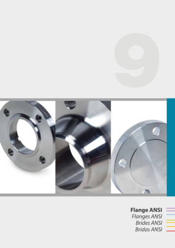
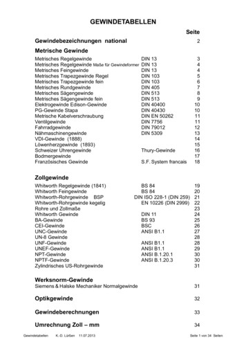
Sample Horizontal Termination AssemblySupport Brackets Required3 ft. (0.91 m)MinimumBetween Brackets3 ft. (0.91 m)MinimumBetween BracketsHeader Tees Should be Schedule 40 Drain Tees.Do Not Use Sharp Turn Tee’s or ElbowsExhaustTermination:Tee or ElbowCombustion AirTermination:Tee or ElbowCondensate Trap6 in (152 mm)MinimumNOTEVent termination per ANSI Z223.1/NFPA 54. Forclearances not specified in ANSI Z223.1/NFPA 54,clearances are in accordance with local installationcodes and the requirements of the gas supplier.PVC/CPVC Common Venting Installation InstructionsCopyright 2018 Rinnai America Corporation. All Rights Reserved.14
Sample Vertical Termination Assembly-Room AirSupport Brackets RequiredExhaustTermination:Elbow3 ft. (0.91 m)MinimumBetween BracketsHeader Tees Should be Schedule 40 Drain Tees.Do Not Use Sharp Turn Tee’s or Elbows3 ft. (0.91 m)MinimumBetween BracketsCondensate Trap6 in (152 mm)MinimumRoom Air applications shouldinclude an elbow and ventscreen or room air filter.PVC/CPVC Common Venting Installation InstructionsCopyright 2018 Rinnai America Corporation. All Rights Reserved.NOTEVent termination per ANSI Z223.1/NFPA 54. Forclearances not specified in ANSI Z223.1/NFPA 54,clearances are in accordance with local installationcodes and the requirements of the gas supplier.15
Maintenance ClearancesTopics in this section Water Heater ClearancesVertical Termination ClearancesHorizontal Termination ClearancesIf the vent system is to be enclosed, it is suggested that the design of the enclosure shall permit inspection of the ventsystem. The design of such an enclosure shall be deemed acceptable by the installer or the local inspector.Water Heater ClearancesRefer to the Rinnai Tankless Water Heater Installation and Operation Manual for minimum clearance requirementsaround the water heater.Vertical Termination Clearances (All System Sizes)There should be a minimum of 12 in. (305 mm) between exhaust and intake terminations.Clearances of Brackets:All supports, such as wall brackets or spacer blocks, must be installed with a maximum distance of 78 in. (2 m) betweeneach support. Additional supports can be installed before and after an elbow if needed.Freestanding Components:Components which are installed freestanding for vertical termination with a length of over 59 in. (1.5 m), must beadditionally secured to the building with guys or braces.Pitched Roof Termination Clearances:12 in. (305 mm) minExhaust VentCombustion Air12 in. (305 mm)above roof oranticipated snowlevel12 in.(305 mm)minNOTEVent termination per ANSI Z223.1/NFPA 54. Forclearances not specified in ANSI Z223.1/NFPA 54,clearances are in accordance with local installationcodes and the requirements of the gas supplier.PVC/CPVC Common Venting Installation InstructionsCopyright 2018 Rinnai America Corporation. All Rights Reserved.16
Horizontal Termination ClearancesThis appliance, along with the Common Vent System, is certified with the 3 in., 4 in., 6 in. wall termination mounted inthe orientation shown below.ExhaustVentCombustionAir VentCombustionAir VentFrom Exhaust Vent to Combustion Air Vent: Minimum 12 in. (305 mm)CombustionAir VentCombustionAir VentCombustionAir VentCOMBUSTION AIR IS NOT ALLOWEDIN THE SHADED AREAMin 12 in. (305 mm) above grade oranticipated snow levelVent Size3 in., 4 in., 6 in.Separation Distance12 in. MinimumThe exhaust and combustion air terminations must follow these clearances: 12 in. minimum vertically from bottom of combustion air termination to ground or anticipated snow line. 12 in. minimum from edge of exhaust termination to edge of combustion air termination.There should be a minimum of 36 in. (91 cm) between exhaust terminations in multiple common vent installations.Refer to the Rinnai Tankless Water Heater Installation and Operation Manual for maximum vent lengths based on thevent diameter installed.ExhaustVentMINIMUM 12 in. (305 mm)CombustionAir VentNOTEDuring colder weather when the exhausttemperature is much hotter than the outsideair, the exhaust fumes will condense, producingwater vapor. As a result, a plume of watervapor may be seen leaving the exhaust.PVC/CPVC Common Venting Installation InstructionsCopyright 2018 Rinnai America Corporation. All Rights Reserved.17
Combustion Air RequirementsCommon Vent Applications Utilizing Room AirCondensate Trap6 in (152 mm)MinimumThis rack system requires adequate combustion air for ventilation and dilution of flue gases. Failure to provideadequate combustion air can result in unit failure, fire, explosion, serious bodily injury or death. Use the followingmethods to ensure adequate combustion air is available for correct and safe operation of this rack system.Important: Combustion air must be free of corrosive chemicals. Do not provide combustion air from corrosiveenvironments. System failure due to corrosive air is not covered by warranty.Combustion air must be free of acid forming chemicals such as sulfur, fluorine and chlorine. These chemicals have beenfound to cause rapid damage and decay and can become toxic when used as combustion air in gas appliances. Suchchemicals can be found in, but not limited to bleach, ammonia, cat litter, aerosol sprays, cleaning solvents, varnish,paint, and air fresheners. Do not store these products or similar products in the vicinity of the water heater system.Unconfined Space:An unconfined space is defined in National Fuel Gas Code, ANSI Z223.1/NFPA 54 as “a space whose volume is not lessthan 50 cubic feet per 1,000 Btu/hr (4.8 m 3 per kW per hour) of the aggregate input rating of all appliances installed inthat space. Rooms communicating directly with the space in which the appliances are installed, through openings notfurnished with doors, are considered a part of the unconfined space.” If the “unconfined space” containing the systemis in a building with tight construction, additional outside air may be required for proper operation. Outside airopenings should be sized the same as for a confined space.Confined Space:(Small Room, Closet, Alcove, Utility Room, Etc.)A confined space is defined in the National Fuel Gas Code, ANSI Z223.1/NFPA 54 as "a space whose volume is less than50 cubic feet per 1,000 Btu/hr (4.8 m3 per kW per hour) of the aggregate input rating of the combined appliancesinstalled in that space." A confined space must have two combustion air openings. Size the combustion air openingsbased on the BTU input for all gas utilization equipment in the space and the method by which combustion air issupplied.PVC/CPVC Common Venting Installation InstructionsCopyright 2018 Rinnai America Corporation. All Rights Reserved.18
Louvers and GrillsWhen sizing the permanent opening, consideration mustbe taken for the design of the louvers or grills to maintainthe free area required for all gas utilizing equipment inthe space. If the free area of the louver or grill design isnot available, assume wood louvers will have 25% freearea and metal louvers or grills will have 75% free area.Under no circumstance should the louver, grill or screenhave openings smaller than 1/4 in.ExhaustExample:Wood: 10 in x 12 in x 0.25 30 in2Metal: 10 in x 12 in x 0.75 90 in212 in. (305 mm)10 in.(254 mm)(Be sure to maintain 12 in. (305 mm) above grade oranticipated snow level)LocationTo maintain proper circulation of combustion air, twopermanent openings (one upper, one lower) must bepositioned in confined spaces. The upper shall be within12 in. (305 mm) of the top of the confined space and thelower opening shall be within 12 in. (305 mm) of thebottom of the confined space. Openings must bepositioned as to never be obstructed.Vent termination per ANSI Z223.1/NFPA 54. Forclearances not specified in ANSI Z223.1/NFPA 54,clearances are in accordance with local installationcodes and the requirements of the gas supplier.Using Outdoor Air For CombustionOutdoor air can be provided to a confined space throughtwo permanent openings, one commencing within 12 in.(305 mm) of the top and one commencing within 12 in.(305 mm) of the bottom of the confined space. Theopenings shall communicate to the outside by one of twoways.PVC/CPVC Common Venting Installation InstructionsCopyright 2018 Rinnai America Corporation. All Rights Reserved.19
Vent termination per ANSI Z223.1/NFPA 54. Forclearances not specified in ANSI Z223.1/NFPA 54,clearances are in accordance with local installation codesand the requirements of the gas supplier.When communicating indirectly with the outdoorsthrough vertical ducts, each opening shall have aminimum free area of 1 in2/4,000 Btu/hr (550 mm2/kW)of total input rating of all appliances in the confinedspace. Combustion air to the appliance can be providedfrom a well ventilated attic or crawl space.ExhaustTO PREVENT POSSIBLEPERSONAL INJURY OR DEATHDUE TO ASPHYXIATION, COMMON VENTING WITHOTHER MANUFACTURER’S INDUCED DRAFT APPLIANCESIS NOT ALLOWED.WARNINGChecklist for Combustion Air andVenting Requirements Verify proper clearances around the vents. Ensure that the “Combustion Air Requirements”(Be sure to maintain 12 in. (305 mm) above grade oranticipated snow level)NOTECombustion air provided to the system shouldnot be taken from any area of the structurethat may produce a negative pressure (such asexhaust fans or powered ventilation fans).Using Indoor Air For CombustionWhen using air from other room(s) in the building, thetotal volume of the room(s) must be of adequate volume(greater than 50 cubic feet per 1,000 Btu/hr). Eachcombustion air opening must have at least one square inchof free area for each 1,000 Btu/hr, but not less than 100square inches each.are followed that will provide sufficientcombustion air for the appliance. Ensure approved venting components have beenused. All horizontal vent runs must be sloped up awayfrom the water heater a minimum of 1/4 in.(6 mm) per foot. Verify that there is adequate combustion air. Installation complies with National Fuel Gas Code,ANSI Z223.1/NFPA 54, as well as local and stateregulations therein.When communicating directly with the outdoors throughhorizontal ducts, each opening shall have a minimum freearea of 1 in2/2,000 Btu/hr (1,100 mm2/kW) of total inputrating of all appliances in the confined space.Note: If ducts are used, the cross sectional area of the ductmust be greater than or equal to the required free area ofthe openings to which they are connected.PVC/CPVC Common Venting Installation InstructionsCopyright 2018 Rinnai America Corporation. All Rights Reserved.20
Exhaust Vent Termination ClearancesDirect Vent for indoor models, you must install terminations to bring in combustion air and expel exhaust.TERMINATIONXAIR SUPPLY INLETVVENT TERMINALClearance inRef. A alsoapplies toanticipatedsnow lineAREA WHERE TERMINALIS NOT PERMITTTEDSNOWRefDescri
Training on Rinnai Tankless Water Heaters is accessible at www.trainingevents.rinnai.us A trained and qualified professional must test the ommon Venting System for leaks before use. The installation must conform to the Rinnai Tankless Water Heater Installation and Operation Manual that is