Transcription
YAESUFT-450FT-450ATUsers Manual18 August 2013
Authors MessageWhen I started this project, I did so thinking that the Yaesu Manual was too confusing and hard to learnfrom. Besides, writing a User’s Manual is a great way to learn any system.Well, I have to say, I was wrong about the first item. It turns out the Yaesu Manual is very good. It is justthat the FT-450 is a very complex machine. I continued with the effort because my second reason is stillvalid. And I wanted a shorter reference manual, structured closer to the way I think, to provide myselfwith a slightly different perspective of this impressive machine.You will find that this is structured to my machine. I do not have the enhanced microphone, a linearamplifier to boost up the power, and as yet I do not have the software in my computer to drive RTTY ,packet, or slow scan video.Where Yaesu’s version of the manual gives explicit instructions on an entire task, I have tried to break itdown to functional procedures and presume that the reader will learn these basic procedures so that I donot have to spell out the specifics of every keystroke over and over again.The only area covered by this document that was not clear in the Yaesu manual is found in section 5.2where I discuss the interaction between M-TUNE, VFO-A, and VFO-B.
YAESU HF/50 mHz Transceiver FT-450 User’s ManualTable of ContentsGeneral . 1Controls . 12.1Power . 33Receiver . 43.1Communications Mode . 43.2Band . 43.3VFO (Variable Frequency Oscillator). 53.3.1 Clarifier . 63.3.2Split Frequency Operation . 63.4Extracting the Signal from the Noise . 73.4.1 RF Attenuation and Intercept Point Optimization (IPO) . 73.4.2 Noise Blanking . 73.4.3 Digital Signal Processor . 73.4.3.1Contour . 8123.4.3.2Notch . 83.4.3.3 Digital Noise Reduction (DNR) . 83.4.3.4Band Pass Width. 83.4.3.5 Filter Shift . 93.4.4CW Reverse . 93.4.4.6 CW Spotting . 93.4.5 Radio Frequency Gain. 93.4.5.7 Automatic Gain Control . 93.4.5.8 Radio Frequency Volume Control. 103.4.6Audio Volume Control. 103.4.7 Signal meter . 104Transmitter. 104.1Transmission . 114.1.1 Microphone Button . 114.1.2 Voice Activated Transmitter Switching (VOX) . 114.1.3 CW Break-In . 114.1.4 Data . 114.2Meter . 114.3Automatic Antenna Tuner . 125Channel Memories . 125.1Memory Content. 125.2Tuning of the VFO Setup Memory . 135.3Band VFO Setup Memory . 145.4Home Memory . 145.5Quick Memory . 145.6Channels Memories . 155.6.1 Recall . 155.6.2 Storage. 155.6.3 Removal . 155.6.4 Labeling . 155.7VFO Memory Scanning . 16-i-
YAESU HF/50 mHz Transceiver FT-450 User’s Manual67895.8Programmable Memory scanning .16System Controls .166.1Display Brightness .166.2Semi-automatic Keyer .166.3Custom Switch .16Adaptation (Menu) .187.1Transceiver function operational parameters .207.2Tranceiver Controls .217.3Computer Aided Transceiver (CAT) Operation .227.4Adaptation of CW communication.227.5Adaptation to exclude bands and modes .247.6Adaptation for microphone .247.7Adaptation of repeater communication.247.8Adaptation of Data communication.257.9Adaptation of RTTY communication .257.10Adaptation of VOX Operation.25Procedural Uses .258.1CW Setup .258.2SSB Setup.268.3Antenna Testing .278.4CW Training .27Acronym Glossary.28Table of TablesTable 1 - Controls.3Table 2 – Communication Modes .4Table 3 – Transceiver Bands .5Table 5 – Base frequency step size for controls .5Table 6 – Band Width Filter Settings .9Table 7 – Memory Channel Number .12Table 8 – Contents of Each Memory Channel.13Table 9 – 20 Unique Assignable Button Functions .17Table 10 – 8 Assignable shortcuts of F followed by an existing buttons .17Table 11 – 22 Duplicate Button Functions.18Table 12 – Miscellaneous redundant or useless function.18Table 13 – Adaptable Parameters .20Table 14 – CTCSS tone frequencies (Hz) .21- ii -
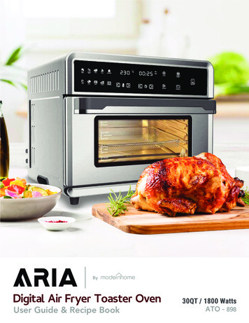
YAESU HF/50 mHz Transceiver FT-450 User’s Manual1GeneralThe Yaesu FT-450 HF/50 MHz Transceiver is designed for Amateur Radio use. It provides ageneral-purpose receiver covering 30 KHz through 56 MHz. The Transceiver range is brokeninto 10 Amateur Radio Bands and 1 general purpose band to cover the remaining high frequencyspectrum. The variable frequency oscillator (VFO) setup for each band is rememberedindividually as you switch bands. The details of what makes up a VFO setup will be describedwhen we get into the section on memory. The transceiver allows communication in using sideband, continuous wave, amplitude modulation, frequency modulation, and (when computerdriven) a number of data modes.2ControlsThe FT-450 front panel contains 24 push buttons, 3 analog rotary dials, 2 rotary digital dials, a lighteddisplay, and three jacks. The small rotary digital dial (“DSP/SEL”) has 24 steps per revolution and alsofunctions as a push button. The large rotary digital dial has 100 steps per revolution. A number of pushbuttons behave differently if held down for one second (adaptable).Since there are literally hundreds of settings possible on the FT-450, a button, knob, or dial may be usedto control more than one function. The less often changed values are set by a sequence of buttons and/ordials. For example, if you press the “F ” button (2nd from right mid height button), the letter F willilluminate on the display. The upper right six buttons have two names on each. If the F is illuminated, thebutton performs the function of the upper name and the F is extinguished. Otherwise those buttonsperform the function of the lower name.Definitions:f-press press a button preceded by the “F ” buttont-press press a button and hold for 1 second (adaptable 0.5, 1.0, 1.5, or 2.0 seconds)-1-
YAESU HF/50 mHz Transceiver FT-450 User’s ManualCONTROLON/OFFDSPATT/IPOBAND AND DE PRESST-PRESSPRESST-PRESSMODE PRESSA trainpower off-menuCWpower off-menuCW-MEMORYPRESSMAIN le system ON/OFFStep DSP contour, notch, digital noise reduc, width, OFFStep through combinations of ATT and IPO off and onVoice tone to compare with CW tone to spot the frequencyToggles noise blankerStep automatic gain control through auto, fast, slowTurn off automatic gain controlSteps forward through enabled bandsSteps forward through bands to enable/disableSteps backward through enabled bandsSteps backward through bands to enable/disableToggle enable/disable of automatic antenna tunerStart tuning to antenna processEnter the “F ” (function) stateGenerates the next group of 5 practice CW charactersEnter or leave the “menu” state (see section 6 adaptation)Reset adaptation to factory default when turn power onStep through power, ALC, standing wave ratio meterStart brightness adjustment via DSP/SQL(end with press)Steps forward through enabled modesSteps forward through modes to enable/disableToggles between USB and LSB receptionDisplay software version (194) when turn power onSteps forward through enabled modesSteps backward through modes to enable/disableToggles between USB and LSB receptionCopy the current VFO settings into the secondary VFOSwap the current and secondary VFO settingsToggle CW keyer on/off (manual vs space assisted keying)Allow offset of receive frequency with “MAIN” dialToggle increase in frequency steps for both dialsLock frequency (see details) to avoid accidental changeShift the intermediate frequency (IF) pass bandSmall kHz steps in frequency (see Table 5)100 KHx steps in frequency (may be adapted to set CWside tone, CW speed, 1 mHz steps, mic gain, or rf power)single channel stepssingle groups stepsStep values for selected filter (shown by “ ”)Step through list of adaptable itemsStep through allowed values fore individual itemsToggle between small and large steps in frequencyToggle between groups and individual memory numbersToggle type of filter on/off, sense, magnitude (see writeup)select menu item (blink menu display) for settingFine setting of frequency (end memory mode)-2-
YAESU HF/50 mHz Transceiver FT-450 User’s ManualCONTROLSQL/RF GAINACTTURNAF SSPRESSSTATEnot squelchsquelchFFpower offFF MWmenu blinkpower onFFF-FUNCTIONAnalog setting of radio frequency gainAnalog setting of squelch levelAnalog setting of audio frequency gainAnnounce the frequency and mode in voice to operator,Customer adapted function ( see Tables 9, 10, 11, 12)Memory write VFO setup to selected channel (1 out of 508)Copy memorized VFO setup into current VFOClear memory channels when power turned onCopy preferred (quick) VFO setup into current VFOCopy quick VFO setup into current VFOCopy current VFO setup into home channelIn most cases, the menu item restored to factory defaultReset adapt, clear memory channels when turn power onActivate or deactivate voice activated transmissionCopy current VFO setup into (preferred (quick) memoryToggle setting frequency step with DSP/SEL knobToggle operation using secondary VFO settings to transmitActivate quick SPLIT operationToggle program memory scan between two frequenciesToggle upward scanning of frequencies or memory channelTable 1 - ControlsThis document was derived from the information in the Yaesu HF/50 MHz Transceiver FT-450 OperationManual.2.1PowerTo toggle the FT-450 transceiver ON or OFF, t-press the ON/OFF button. Some portion ofthe display will show when the unit is on. Needless to say, the 12 volts must already besupplied to the unit.The power switch is also used to reset memory and/or adaptation in the FT-450. Warning: Do not performany of the first three following steps unless you are prepared to lose information:1) Turning the power on while holding the “F ” button will restore adaptationto the factory default settings.2) Turning the power on while holding the “VM/V/M” button will clear all memorychannels except QMB.3) Turning the power on while holding the “HOME/RCL” button will bothrestore adaptation to the factory default settings and clear all memory channelsexcept QMB.-3-
YAESU HF/50 mHz Transceiver FT-450 User’s Manual4) Turning the power on while holding the “MODE ” button will display the current softwareversion. You must then turn the power off and then on to resume normal operation.3ReceiverThe transceiver provides both a multi-band sensitive receiver and transmitter. Most of thecontrols have to do with the operation of the receiver section. However, Mode, Band, and VFOapply to the transmitter section as well.3.1Communications ModeThe FT-450 transceiver is designed to communicate using Lower Side Band(LSB), Upper Side Band (USB), Continuous Wave (CW, i.e. Morse code),Data (DATA), Amplitude Modulation (AM), or Frequency Modulation (FM).Pressing either the “MODE ” or “MODE ” will step through the availablemodes in the forward or reverse direction respectively. These buttons are found to the right of the“DSP/SEL” knob. Any unwanted modes may be turned off in adaptation using the MENU functionsdescribed later.Most user’s will not need all of the communication modes shown in Table 2. When you get to the sectionon adaptation, you will find that you can configure the system to skip any modes that are not needed.MODEDESCRIPTIONUSBUpper side bandLSBLower side bandCWContinuous WaveAMAmplitude ModulationFMFrequency ModulationDATARadio teletype, PacketTable 2 – Communication Modes3.2BandStep through the bands using ”BAND ” and “BAND ” buttons on eitherside of the “MAIN” dial. Only those bands enabled (via the menucommand) will be selected. The available bands are shown in Table 1above. Any unwanted bands may be turned off in adaptation using theMENU functions described later.BANDGEN1.8 MHz3.5 MHz7.0 MHz10 MHz14 MHzRANGE30 KHz 33 MHz30 KHz 33 MHz30 KHz 33 MHz30 KHz 33 MHz30 KHz 33 MHz30 KHz 33 MHz-4-AMATEUR RADIO BANDnone (stores non-ham fqys )1.8 MHz 2.0 MHz3.5 MHz 4.0 MHz7.0 MHz 7.3 MHz10.1 MHz 10.15 MHz14 MHz 14.35 MHz
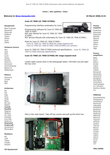
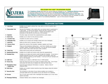
YAESU HF/50 mHz Transceiver FT-450 User’s ManualBAND18 MHz21 MHz24 MHz28 MHz50 MHz3.3RANGEAMATEUR RADIO BAND30 KHz 33 MHz18.068 MHz 18.168 MHz30 KHz 33 MHz21 MHz 21.45 MHz30 KHz 33 MHz24.89 MHz 24.99 MHz30 KHz 33 MHz28 MHz 29.7 MHz33 MHz 56 MHz50 MHz 54 MHzTable 3 – Transceiver BandsVFO (Variable Frequency Oscillator)The display shows the current frequency in 10 Hz increments (left field is MHz, midfield is KHz). The desired frequency is selected by rotating the “DSP/SEL” knob (24steps per revolution). Tabke 5 shows the incremental step size. Factory defaults arehighlighted.Press the “DSP/SEL” knob to blink the left 3 digits ofthe frequency display and the “DSP/SEL” knob nowmoves in 100 kHz increments changing only thosedigits. Pressing the “DSP/SEL” knob again (or pressingany button or moving the “MAIN” dial) stops theblinking and the “DSP/SEL” knob action returns to thesmaller increment size.The “MAIN” (large unlabeled) dial (100 steps perrevolution) allows fine-tuning of the frequency. The“MAIN” dial is, by default, disabled in AM or FMmodes, but may be enabled by adaptation.MODE(S)“DSP/SEL” KNOBCW, LSB, USB, DATA 1.0, 2.5, 5.0 kHzAM2.5, 5.0, 9.0, 10, 12.5, 25 kHzFM5.0, 6.25,10, 12,.5, 15, 20, 25, 50 kHzTable 5 – Base frequency step size for controls“MAIN” DIAL1, 10, 20 Hz100, 200 Hz *100, 200 Hz **Note: By default, “MAIN” dial is inoperative for AM and FM modes unless enabled by adaptation.To change the frequency step size of the “DSP/SEL” knob, f-press the “STEP/SPLIT” (just above “F ”).The current step size will show on the bottom right of the display. Change the step size value by rotatingthe “DSP/SEL” knob. When the correct value is displayed, press the “STEP/SPLIT” button to exit thatstate.Press the “FAST” button (to the left bottom of “MAIN” dial) to increase the speed of frequency selection.The word FAST will be highlighted on the display, the “DSP/SEL” increments will be doubled and the“MAIN” dial increments will be increased by a factor of 10. Pressing “FAST” again to extinguish theFAST highlight and returns both knobs to their set increments.The current frequency may be locked to avoid inadvertently changing it. To toggle the lock function,press the “LOCK” button to the right of the “MAIN” dial. When locked, the word LOCK will appear-5-
YAESU HF/50 mHz Transceiver FT-450 User’s Manualabove the right end of the frequency display. The frequency lock may be released by pressing “LOCK”again.In addition to the display, the FT-450 is able to announce the current frequency throughthe speaker or headset. To hear the frequency, f-press the “VOICE” button (2nd upperbutton from the right).Note: Small changes in the receive frequency (under 10 kHz) my also be achieved by useof the clarifier. See section 4.1.1 of transmission for details.3.3.1ClarifierThe receive frequency can be set up to /-9.99 kHz differentfrom the transmit frequency. This is toggled on and off bypressing the “CLAR” button located near the bottom middleof the front panel. When activated, the word CLAR showson the right side of the display with the offset shown belowit (replacing the M-TUNE, VFO-A, or VFO-B on thedisplay). The offset value may be changed with the “MAIN”dial. Note that the offset control may be re-assigned to the“DSP/SEL” knob in adaptation using the MENU functions as described later.The system will remember the offset value, even when CLAR is turned off. To zero the offset, t-press the“CLAR” button while the clarifier is turned on. The offset will also be set to zero if the “MAIN” dial isinadvertently turned when the CLAR is turned off.3.3.2Split Frequency OperationThe FT-450 Transceiver is capable of operating on two frequencies; onefor transmission and another for reception. Moreover, there is no restrictionthat the two VFOs operate on the same band or even in the same mode.To toggle split frequency operation, press the “STEP/SPLIT” button. Thework SPLIT is highlighted in the display. The current receive VFO setupappears on the display. If you want to keep it, press either the “A B” or “A/ B” button to either put that setup in the transmit VFO or swap setups withthe current transmit VFO. Then enter the transmit frequency and any other parametersassociated with it and press the “A / B“ button to swap it with the receive VFO setup.You are now ready to communicate. Whenever the Transceiver is transmitting, the frequencydisplay will show the transmit frequency. Otherwise it will show the receive frequency.There is also a quick split feature in the system. If you t-press the “STEP/SPLIT” button, thesystem will automatically copy the receive VFO into the transmit VFO and add 5 kHz to thetransmit frequency. You may now communicate as before.Note: see section 5 for a better understanding of the contents of a VFO setup and section 5.5 amore complete description of the “A B” or “A / B” button action.-6-
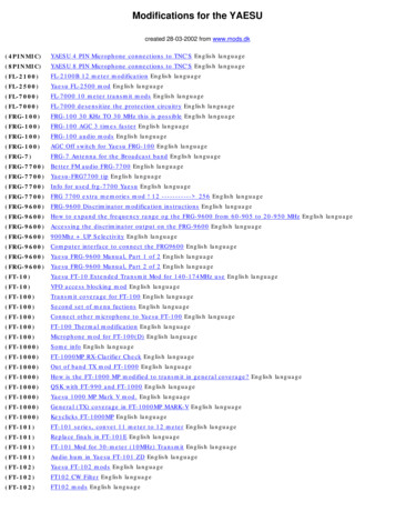
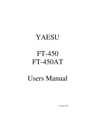
YAESU HF/50 mHz Transceiver FT-450 User’s Manual3.4Extracting the Signal from the NoiseEvery stage of the FT-450 Transceiver contributes to the effort to improve the signal to noiseratio. In order to deal with the wide dynamic range of input signals, the operator may optionallyinsert 20 db of attenuation or disable the radio frequency (RF) amplifier in what is calledintercept point optimization (IPO). The RF amplifier gain is controlled by the automatic gaincontrol (AGC) circuitry.The signal is then mixed with the first local oscillator to produce an intermediate frequency of67.899 mHz, passed through a 10 kHz wide roofing filter and then passed through the firstintermediate frequency (IF) amplifier. The gain of the IF amplifier is also controlled by the AGCcircuitry.The amplified IF signal is mixed to produce a 24 kHz second IF. The second IF signal is thenconverted through an analog to digital converter (ADC). Further filtering is then performed bythe digital signal processor (DSP). The DSP then detects (DET) the signal and provides the AGCcontrol. The detected signal then passes through a digital to analog converter (DAC) to drive thespeaker circuitryThe operator has direct control of ATT, IPO, noise blanker (NB), several DSP filter properties,AGC speed, IF gain (or squelch), and audio frequency (AF) gain.3.4.1RF Attenuation and Intercept Point Optimization (IPO)Filtering is done first by the “ATT/IPO” button. To reducestrong signals, apply these filters. Each time the“ATT/IPO” button is pressed it advances through thesequence:ATT off, IPO offATT on, IPO offATT off, IPO onATT on, IPO on3.4.2no attenuation, input preprocessor active20 db attenuation, input preprocessor activeno attenuation, input processor off20 db attenuation, input processor offNoise BlankingInterference rejection within the bass band follows the IF filtering. This is used to filter noise fromautomobiles or any other electrical sparks. It is toggled on and off by the “NB” button and the display willshow the status of the NB on the second figure top right on the display.3.4.3Digital Signal ProcessorPressing the “DSP” button will cause a “ ” sign toappear in front of the CONTOUR signal processing-7-
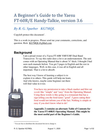
YAESU HF/50 mHz Transceiver FT-450 User’s Manualgraph on the left side of the display. Repeated press of the “DSP” button will move the “ ” sign down tothe NOTCH graph, then to the DNR graph, then to the WIDTH, and finally to remove the “ ” sign. Whilethe “ ” sign is displayed and if M-TUNE, VFO-A, or VFO-B shows on the bottom right of the screen, the“DSP/SEL” knob is used to adjust the digital signal processor parameters.3.4.3.1ContourThe shape of the band pass may be rounded up or downover a small or medium width of the band pass. Thatbulge may be moved over the width of the band pass.The first press of the “DSP” button causes the “ ” signto be positioned next to the CONTOUR graph. Pressingthe “DSP/SEL” knob steps the filter from none tonarrow to medium with bulge. T-press the “DSP/SEL”knob to flip between and upward or downward bulge.Turn the “DSP/SEL” knob to position the bulge over thedifferent parts of the band pass.3.4.3.2NotchIntroducing a sharp notch in the band pass is achieved by the secondpress of the “DSP” button that causes the “ ” sign to be positionednext to the NOTCH graph. Press the “DSP/SEL” knob to toggles thefilter off or on. Turn the “DSP/SEL” knob to position the bulge overthe different parts of the band pass. Note that the knob must be movedseveral steps before the notch will move noticeably.3.4.3.3Digital Noise Reduction (DNR)Application of one of 11 different digital Noise Reduction (DNR) filters in the band pass is achieved bythe third press of the “DSP” button that causes the “ ” sign to be positioned next to the DNR indicator.Press the “DSP/SEL” knob to toggle the DNR off or on. Rotate the “DSP/SEL” to select one of the filterswhich are indicated in the number of segments lighted by listening to which sounds best.3.4.3.4Band Pass WidthWithout any other filtering, the band pass is relativelyflat for its band pass value with relatively steep dropoff above and below that band. The fourth push of the“DSP” button causes the “ ” sign to be positionednext to the WIDTH graph on the display. Turning the“DSP/SEL” knob steps the filter from narrow (left),nominal (mid), to wide (right). The actual band width-8-
YAESU HF/50 mHz Transceiver FT-450 User’s Manualdepends on the communications mode as shown in Table 6.MODECW, DATAUSB, LSBAMFM3.4.3.5NARROWNOMINALWIDE500 Hz1.8 kHz2.4 kHz1.8 kHz2.4 kHz3.0 kHz3.0 kHz6.0 kHz9.0 kHz2.5 kHz5.0 kHz--------Table 6 – Band Width Filter SettingsFilter ShiftThe digital signal processor center frequency canalways be shifted with the “SHIFT” knob. Theposition of that center frequency is shown on thelower left of the display.Note: The shift value is not saved as part of theVFO setup.3.4.4CW ReverseThe default CW reception injects the beat frequency inthe upper sideband of the CW carrier. In some cases, anear signal may be filtered
When I started this project, I did so thinking that the Yaesu Manual was too confusing and hard to learn from. Besides, writing a User's Manual is a great way to learn any system. Well, I have to say, I was wrong about the first item. It turns out the Yaesu Manual is very good. It is just that the FT-450 is a very complex machine.