Transcription
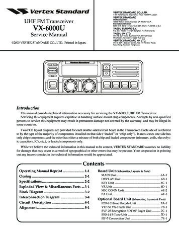
VERTEX STANDARD CO., LTD.4-8-8 Nakameguro, Meguro-Ku, Tokyo 153-8644, JapanVERTEX STANDARDUHF FM TransceiverUS Headquarters10900 Walker Street, Cypress, CA 90630, U.S.A.International Division8350 N.W. 52nd Terrace, Suite 201, Miami, FL 33166, U.S.A.VX-6000UYAESU EUROPE B.V.P.O. Box 75525, 1118 ZN Schiphol, The NetherlandsService ManualYAESU UK LTD.Unit 12, Sun Valley Business Park, Winnall CloseWinchester, Hampshire, SO23 0LB, U.K.VERTEX STANDARD HK LTD. 2003 VERTEX STANDARD CO., LTD. Printed in Japan.Unit 5, 20/F., Seaview Centre, 139-141 Hoi Bun Road,Kwun Tong, Kowloon, Hong KongPOWERIntroductionThis manual provides technical information necessary for servicing the VX-6000U UHF FM Transceiver.Servicing this equipment requires expertise in handling surface-mount chip components. Attempts by non-qualifiedpersons to service this equipment may result in permanent damage not covered by the warranty, and may be illegal insome countries.Two PCB layout diagrams are provided for each double-sided circuit board in the Transceiver. Each side of is referredto by the type of the majority of components installed on that side (“leaded” or “chip-only”). In most cases one side hasonly chip components, and the other has either a mixture of both chip and leaded components (trimmers, coils, electrolytic capacitors, ICs, etc.), or leaded components only.While we believe the technical information in this manual to be correct, VERTEX STANDARD assumes no liabilityfor damage that may occur as a result of typographical or other errors that may be present. Your cooperation in pointingout any inconsistencies in the technical information would be appreciated.ContentsOperating Manual Reprint . 1-1Cloning . 2-1Specifications . 2-2Exploded View & Miscellaneous Parts . 3-1Block Diagram . 3-2Interconnection Diagram . 3-4Circuit Description . 4-1Alignment. 5-1Board Unit (Schematics, Layouts & Parts)MAIN Unit . 6A-1DISPLAY Unit . 6B-1KEY Unit . 6C-1VR Unit . 6D-1MIC CONN Unit . 6E-2PA Unit . 6F-1Optional Board Unit (Schematics, Layouts & Parts)F2D-8 2-Tone Decode Unit . 7A-1VTP-50 VX-Trunk Unit. 7B-1FVP-25 Encryption / DTMF Pager Unit . 7C-1F5D-14 5-Tone Unit . 7D-1FIF-7 Connection Unit . 7E-11
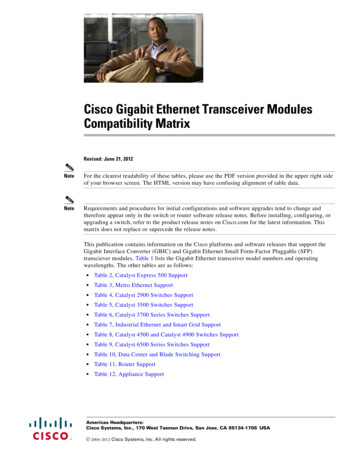
Operating Manual ReprintCONTROLS & CONNECTORSFront Panel‚ƒ †„POWERˆ ‰ Š‡À POWER ButtonPress the button to turn the transceiver ON andOFF.Á TX IndicatorThis lamp glows red when the radio is transmitting. BUSY IndicatorThis lamp glows green when the channel is busy.The display include an 8-character alpha-numericsection showing channel and group names, status and identity information, and error messages.Additional indicators on the display show priority channel assignments and scan include / exclude selection.Å SQC IndicatorThis lamp glows orange when incorrect positionat the setting of CE49.This button can be set up for special applications,such as high/low power selection, monitor, dimmer, talk-around, and call alert function, as determined by your network requirements and programmed by your VERTEX STANDARD dealer.Ç VOLUME KnobÈ EMERGENCY MicrophoneThis channel on “INTERCOM” ListReceiver MonitorThis channel on“SCAN” ListThis channelon “OPTION”ListPressing these buttons changes the current group(and displayed group number or name). Holding this button for more than 1/2 second causesthe function to repeat.This knob sets the volume of the receiver.This channel on“SELECTABLE TONE” ListThis channel on“HORN ALERT” ListÄ p/q ButtonÆ Programmable Function Button (PF button)à Liquid Crystal DisplayThis channel on “PUBLICA DDRESS ” or “S PEAKER ”List Channel GroupNumberThe emergency microphone is located behind thissmall slit. When the emergency feature is activated, this Microphone is enabled.É CHANNEL Selector KnobThis knob select the operating channel.Programmable Function Button (PF button)This button can be set up for special applications,such as high/low power selection, monitor, dimmer, talk-around, and call alert function, as determined by your network requirements and programmed by your VERTEX STANDARD dealer.8 Character Alpha-numeric DisplayThis channel on “AUX A/B/C” List1-1
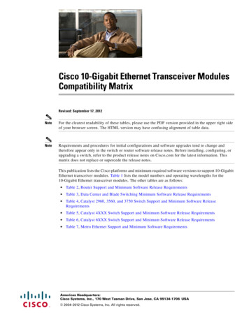
Operating Manual ReprintCONTROLS & CONNECTORSSide PanelMicrophone Jack (It is on both sides.)Connect the microphone plug to this jack.Microphone JackREAR (Heatsink) ‚ ƒ„À Antenna SocketThe 50-ohm coaxial feedline to the antenna mustbe connected here, using a type-M (PL-259) plug.Á External Speaker JackAn external loudspeaker may be connected to this2-contact, 3.5-mm mini-phone jack.Caution: Do not connect this line to ground, and becertain that the speaker has adequate capability to handle the audio output from theVX-6000.1-2 13.4-V DC Power ConnectorThe supplied DC power cable must be connectedto this 4-pin connector. Use only the suppliedfused cable, extended if necessary, for power connection.à DSUB 25-Pin Accessory ConnectorExternal TX audio line input, PTT (Push To Talk),Squelch, and external RX audio line output signal may be obtained from this connector for usewith accessories such as data transmission/reception modems, ets.
Operating Manual ReprintBASIC OPERATION OF THE TRANSCEIVERImportant! - Before turning on the radio the first time,confirm that the power connections have been made correctly and that a proper antenna is connected to the antenna jack.Switching Power ON/OFFPush the POWER switch turn on the radio. Thedisplay will become illuminated. The radio willstart up on the last channel used prior to shutdown during the previous operating session.Turn the CHANNEL selector knob to choose thedesired operating channel. A channel name willappear on the display. If you want to select theoperating channel from a different MemoryChannel Group, press the UP (p) or DOWN (q)button to select the Memory Channel Group youwant before selecting the operating channel.Setting the VolumeTurn the VOLUME knob clockwise to increase thevolume, and counterclockwise to decrease it. Ifno signal is present, press and hold in the MONbutton more than 1/2 seconds; background noisewill now be heard, and you may use this to setthe VOLUME knob for the desired audio level.Press and hold the MON button more than 1/2seconds to quiet the noise and resume normal(quiet) monitoring.TransmittingTo transmit, wait until the “BUSY” indicator isoff (the channel is not in use), and press the PTT(Push-To-Talk) switch on the side of the microphone (the “TX” indicator will appear or the “TX”indicator will glow red). While holding in the PTTswitch, speak across the face of the microphonein a clear, normal voice level, and then releasethe PTT switch to receive.Selecting Groups and Channelsm Press the UP (p) or DOWN (q) button (repeatedly, if necessary) to select a differentgroup of channels.m Turn the CHANNEL selector knob to select adifferent channel within the current group.Automatic Time-Out TimerIf the selected channel has been programmed forautomatic time-out, you must limit the length ofeach transmission. While transmitting, a beep willsound five seconds before time-out. Another beepwill sound just before the deadline; the “TX” indicator will disappear and transmission will ceasesoon thereafter. To resume transmitting, you mustrelease the PTT and wait for the “penalty timer”to expire (if you press the PTT before this timerexpires, the timer restarts, and you will have towait another “penalty” period.)1-3
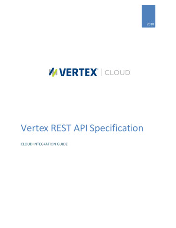
Operating Manual ReprintADVANCED OPERATIONProgrammable Function Button (PF button)The VX-6000 includes the seven ProgrammableFunction Buttons (PF button). The PF buttonfunctions can be customized, via programmingby your VERTEX STANDARD dealer, to meetyour communications/network requirements.Some features may require the purchase and installation of optional internal accessories. Thepossible PF button programming features are il-lustrated at the below, and their functions areexplained on next page.For further details, contact your VERTEX STANDARD dealer. For future reference, check the boxnext to each function that has been assigned tothe PF button on your particular radio, and keepit handy.POWERFunctionsProgrammable Function Button (PF button) 1.5 sec 1.5 sec 1.5 sec 1.5 sec 1.5 sec 1.5 sec 1.5 sec 1.5 sec 1.5 sec 1.5 sec 1.5 sec 1.5 sec 1.5 sec 1.5 secNoneSCAN (SCN)Dual WatchCall/ResetTalk-Around (TA)Alpha Numeric (A/N)DIMMER (DIM)Emergency (EMG)Horn Alert (HA)Home Channel (HOM)Intercom (IC)Low Power (LOW)GRP UPGRP DWNCH UPCH DWNAUX AAUX BAUX CPublic Address (PA)Monitor (MON)RCLSelectable Tone (ST)SP*Squelch Level (SQL)CompanderEncryption** (OPT)* requires RMK-40001-4** requires Encryption Unit
Operating Manual ReprintADVANCED OPERATIONChannel ScanThe Scanning feature is used to monitor multiplesignals programmed into the transceiver. Whilescanning, the transceiver will check each channel for the presence of a signal, and will stop on achannel if a signal is present.To activate scanning:m Press the assigned PF button of the “Scan” momentarily to activate scanning.m The scanner will search the channels, lookingfor active ones; it will pause each time it findsa channel on which someone is speaking.To stop scanningm Press the assigned PF button of the “Scan”.m Operation will revert to the channel to whichthe CHANNEL selector knob is set.Note:Your dealer may have programmed yourradio to stay on one of the following channels if you press the PTT switch duringscanning pause:r Current channel (“Talk Back”)r “Last Busy” channelr “Priority” channelr “Home” channelr Scan Start” channelDual WatchThe Dual Watch feature is similar to the Scan feature, except that only two channels are monitored:r The current operating channel; andr The “Priority” channel.To activate Dual Watch:m Press the assigned PF button of the “DualWatch”.m The scanner will search the two channels; itwill pause each time it finds a channel onwhich someone is speaking.To stop Dual Watch:m Press the assigned PF button of the “DualWatch”.m Operation will revert to the channel to whichthe CHANNEL selector knob is set.ARTS (Auto Range Transpond System)This system is designed to inform you when youand another ARTS-equipped station are withincommunication range.During ARTS operation, your radio automaticallytransmits for about 1 second every 25 (or 55) seconds (the interval is programmed by Dealer) inan attempt to Shake hands with the other station.If you move out of range for more than one minutes, your radio senses that no signal has beenreceived, a ringing beeper will sound. If you subsequently move back into range, as soon as theother station transmits, your beeper will sound.The PF Button FunctionThe PF (Programmable Function) button can beprogrammed by the dealer to provide two of theother functions described below.To activate the primary Accessory function, pressthe PF button momentarily. To access the secondary Accessory function (which may include theAlarm), press and hold the PF button for 1.5 seconds or longer.Call/ResetWhen this feature is programmed and a selective call has been received, momentarily press theassigned PF button of the “Call/Reset” to resetthe flashing indicator and mute the receiver, otherwise press the assigned PF button of the “Call/Reset” to sent your radio’s identification code(ANI) to the dispatcher.Talk-AroundThe feature causes the assigned PF button of the“Talk-Around” to select simplex operation onsemi-duplex channels: the transmit frequencybecomes the same as the receive frequency (regardless of any programmed offset for the channel).Note:This feature has no effect on simplex channels.After pressing the button, “-TAKARD-” is displayedon the LCD.Alpha NumericPress the assigned PF button of the “Alpha Numeric” to switch the display between the Group/Channel number, and the Group/Channel name(alphanumeric). A tone will sound each time youswitch between numerical and alphanumericaldisplay.1-5
Operating Manual ReprintADVANCED OPERATIONDIMCH UP/DWNEMG (Emergency)AUX A/B/CPress the assigned PF button of the “DIM” to adjust the brightness of the display and keybackright.Press the assigned PF button of the “EMG” toinitiate an emergency call (requires ANI board).When an emergency call is made, not tone isemitted and the display does not change. To endthe emergency call, turn the transceiver powerOFF.Press the assigned PF button of the “CH UP” or“CH DWN” to select a different channel withinthe current group.Press the assigned PF button of the “AUX A”,“AUX B”, or “AUX C” to turn the output port (respectively).PA (Public Address)Press the assigned PF button of the “PA” to usethe transceiver as a PA amplifier. When you en” apable this function, a tone sounds and “pears on the display. The public address can beused even while scanning and receiving a call.HA (Horn Alert)Press the assigned PF button of the “HA” to turnthe Horn Alert function ON or OFF. If you receive a call from the base station with 2Tone orDTMF signaling, horn alert will activate.When you turn Horn Alert ON, a tone will sound” appears on the display.and “MONI (Monitor)Press the assigned PF button of the “MONI” momentarily to cancel CTCSS and DCS signalingsquelch; the “MON” icon appears on the display.Press and hold this key for 1/2 seconds to hearbackg
VERTEX STANDARD CO., LTD. 4-8-8 Nakameguro, Meguro-Ku, Tokyo 153-8644, Japan VERTEX STANDARD US Headquarters 10900 Walker Street, Cypress, CA 90630, U.S.A. International Division 8350 N.W. 52nd Terrace, Suite 201, Miami, FL 33166, U.S.A. YAESU EUROPE B.V. P.O. Box 75525, 1118 ZN Schiphol, The Netherlands YAESU UK LTD.