Transcription
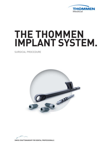
THE THOMMENIMPLANT SYSTEM.SURGICAL PROCEDURE
Content1.Implant specifications55662.Treatment planning778103.EssentialsIndications and contraindicationsClinical useSelection of ideal implant diameter, length and positioningImplant bed preparation13141415154.LabelingColor codingMaterialsSwiss precision to meet the highest expectationsEssentialsPilot drillingImplant bed preparation for the ELEMENT implant lineImplant bed preparation for the CONTACT implant lineUsing the profile drill with implants of varied collar face conditioning with APLIQUIQRemoving the implant from the APLIQUIQ containerRemove the implant from the standard packagingManual implant insertionMechanical implant insertionAlignment of the internal hexagonRemoving the insertion aidPlacement of healing cap (gingiva former)/use of MONO screwdriver24 Healing phase24 Shaping of the gingiva25 Provisional and final restorations2 Thommen Medical
5.Instruments and 1416.Thommen Services42424242427.Surgical cassette for mechanical cleaningGuided SurgeryDrill extensionExtending insertion depth for RC implantsImplant bed preparation in extremely hard boneImplant insertion using a thread tapVECTOdrill twist drill, stainless steel, for single useVECTOdrill twist drill, stainless steel, reusableVECTOdrill twist drill, ceramic, reusableDepth gaugePilot drilling with small diameter drillsMONO torque ratchetMONO insertion device, short, with integrated dental latchMONO screwdriverAdapter for handpiece, one-pieceHealing caps and gingiva formersGingiva former, customizableBone contouring instrument and bone contouring instrument Mucosa punchService set for removal of overly tightened or fractured screwsExplantationomponents of the Thommen Implant SystemLong-term provision of componentsGuaranteeTraining and educationCustomer serviceScientific documentationOverview and appendicess43 Alphabetical index45 Torque values46 NotesBack cover: Drilling protocolss forELEMENT and CONTACT liness (detachable) Thommen Medical3
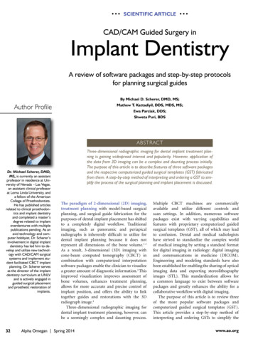
1.Implant specificationsThe clinically relevant characteristics of Thommen implants are definedbelow:PFSLE Core CPF platformRefers to the implant-abutment connection, which constitutes the connection geometry to the abutment. The platform diameter is a key parameter forchoosing the prosthetic components (see next page).C collarCollar height – refers to the absolute height of the machined collar. At0.5 mm in length, the collar of MC implants (Minimized Collar) is shortenedcompared to the Regular Collar (RC). The LC implant (Long Collar) featuresthe longest collar at 2.5 mm.S shoulderRefers to the coronal implant diameter. In the case of MC implants, it is thelevel that is positioned crestally. The shoulder diameter corresponds to theplatform diameter.L endosseous lengthLength of the implant without collar (except in MC implants in which the collarheight is included in the total length L). The length (L) always corresponds tothe endosseous insertion depth (drilling depth) when preparing the implantbed.E endosseous diameterRefers to the largest external diameter of the implant thread (in the cylindrical portion of the implant).Core core diameterRefers to the central diameter of the implant minus the thread, which corresponds to the diameter of the drill hole.4 Thommen Medical
LABELINGThe most important specifications are given on the outer packaging of theproduct for easier orientation:Platform diameterCollar heightImplant lineLength of implantSurface typeReference toinstructions for useAbsolute height ofmachined collarEndosseous diameterIn addition to these important parameters, the label of some products alsoincludes a web address that links to the electronic instructions for use forthe product:Referenceto websiteCOLOR CODINGFor easy identification, each platform diameter of the Thommen Implant System has a specific color:platform 3.5 mm, yellowplatform 4.0 mm, greenplatform 4.5 mm, blueplatform 5.0 mm, greyplatform 6. 0 mm, violetA color-coded label on the implant packaging simplifies logistics and prevents mistakes. If available, all the labels of impression copings and secondary components can also be easily identified by the platform-specific color.Healing caps, gingiva formers and their corresponding impression copingsare also color-coded. Thommen Medical5
MATERIALSAll Thommen implants are manufactured from the proven biocompatiblematerial, pure grade 4 titanium, in accordance with ASTM F 67/ISO 5832-2.SWISS PRECISION TO MEET THE HIGHEST EXPECTATIONSThommen consistently offers our customers and their patients high-qualityproducts. Patient safety has highest priority for Thommen Medical as a developer, manufacturer and distributor of medical devices for dental implantology.To ensure these standards are met, all products are thoroughly quality-checkedby internal and external tests. Thommen Medical is certified in accordancewith: EN ISO 13485:2012 – Directives 93/42/EWG appendix II.3.Thommen Medical is authorized to label every product with the CE marking,which ensures that all Thommen products meet the stringent statutory requirements demanded of medical devices. Thommen Medical quality productsare produced at our own Swiss manufacturing site in Grenchen. All suppliersare chosen very carefully and our collaborations are based on long-standingpersonal relationships. They must meet the strict requirements expected ofmanufacturers of medical technology products. Regular audits enableThommen to monitor a supplier’s performance and to ensure transparencyin quality assurance.Thommen also provides the highest standards of quality to its customers inthe area of research and development, logistics, sales and customer service.This includes regular training and continued education for all employees.6 Thommen Medical
2.Treatment planningESSENTIALSA carefully conducted treatment plan is of utmostimportance for the success of an implant-supportedrestoration.Furthermore, gathering comprehensive patientinformation and the clarification of patients’expectations is crucial.Comprehensive preoperative diagnostics is essential, based on the intended prosthetic solution andbiological conditions. It provides key information forthe surgical procedure, as well as any preparatoryand accompanying measures.It is the responsibility of the implant specialist torefresh and acquire new mandatory medical knowledge through training and continuing education.The creation of optimal bone and soft tissue conditions is an important element of multidisciplinarytreatment planning. It is an effective preventivemeasure for bone preservation after tooth extractions or for bone augmentation. ThommenMedical offers a comprehensive selection of biomaterials for hard and soft tissue regeneration.Thommen Medical offers courses and educationalevents for training in surgery and prosthetics.X-ray templates are available for planning, using2-dimensional X-ray images (see Fo 20d184 andFo 20d185) (see page 10).INDICATIONS AND CONTRAINDICATIONSIf not explicitly stated otherwise, the following indications and contraindicationsapply to both lines of the Thommen Implant System (ELEMENT/CONTACT).More detailed information can be found in the corresponding package leaflets or the electronic instructions for use (see product label).The instructions for use can be viewed at the Thommen website:www.thommenmedical.com. Thommen Medical7
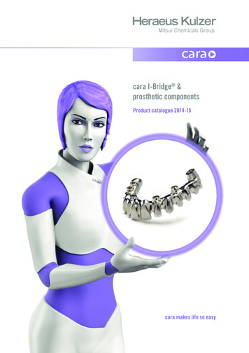
CLINICAL USEImplant linesThommen offers two implant lines: the parallel-walled ELEMENT implant asa universal implant for all indications and the conical-cylindrical implantCONTACT.Due to its conical-cylindrical design, the CONTACT implant is indicated for:· Immediate or delayed placement in extraction sockets.· Special anatomical situations such as converging roots or alveolar ridgeconcavities.In preoperative planning, one should consider that the explantation of aCONTACT implant can be difficult due to its conical-cylindrical design if theapical end of the implant is positioned close to the roots of adjacent teeth.ELEMENT and CONTACT collar heightsELEMENT and CONTACT implant lines are offered with various collarheights.ELEMENT and CONTACT implants with a collar height of 0.5 mm (MC,Minimized Collar) are designed for crestal positioning. Implants with agreater collar height (RC, Regular Collar) should be placed supracrestally.The ELEMENT LC implant (LC, Long Collar) is designed for transgingivalpositioning.Crestal bone level8 Thommen MedicalELEMENT LCCONTACT RCELEMENT RCCONTACT MC0.5 mmELEMENT MC0.5 mm2.5 mm1.5 mm1.0 mm
SurfaceThe surface of the endosseous portion of all implants in the Thommen Implant System is sandblasted and acid-etched.INICELL represents the further development of the sandblasted and thermalacid-etched Thommen surface. The surface chemistry of the microrough implant surface is slightly modified in the conditioning process with APLIQUIQ(see page 18). The superhydrophilic INICELL surface promotes greaterbone-implant contact during the early healing phase and, thus, also definesthe recommended healing times (see page 24).10 μmWith the exception of small-diameter implants (see below), Thommen implants can be subjected immediately to stress loading; however, differenthealing times apply depending on the surface of the implant (see the corresponding package leaflets or electronic instructions for use).Reduced-diameter implantsSmall-diameter implants of the Thommen Implant System are platformⱕ 3.5 mm.Indications, contraindications and requirements for implants of the ThommenImplant System with a diameter less than platform 3.5 mm can be found in thecorresponding instructions for use.In general:· Reduced-diameter implants should only be used where bone volumedoes not permit a larger diameter implant (minimum width of the alveolar ridge 5–6 mm). It is recommended, whenever possible, to block theimplants.Use of small-diameter implants with retentive anchors (such as Dalla Bona ,Tima , Suprasnap or Ecco ) is contraindicated.Small-diameter implants are not suitable for use in areas where pronouncedrotation and translation movements occur and where implants are subjectto large bending moments (e.g. canine region).Short implantsShort implants, such as the 6.5 mm ELEMENT, are only to be used assupplementary and auxiliary implants. Thommen Medical9
SELECTION OF IDEAL IMPLANT DIAMETER, LENGTH ANDPOSITIONINGX-raysX-ray images provide information about vertical bone volume, the relation ofadjacent dental structures to the planned insertion site and the thickness ofsoft tissue. Therefore, they provide important clues in determining the optimal diameter, length and positioning of implants. In order to determine themagnification factor or the scale of the X-ray image, the 5.0 mm X-rayreference sphere (art. no. 3.03.140) can be incorporated into an individual X-ray template.After taking the X-ray images, the respective magnification factor or scalecan be determined in two ways:· By scale comparison of the X-ray reference sphere in the patient’s X-rayimage with the reference sphere in the X-ray template for Thommenimplants (measuring and comparison template with various distortionfactors).· By measuring the size of the X-ray reference sphere in the X-ray imageand calculating the magnification factor.Art. No.ArticleFo 20d184X-ray template for ELEMENT MC,RC and LC implantsFo 20d185X-ray template for CONTACT MCand RC implantsThe X-ray templates for the Thommen Implant System are for guidance purposes only in determining the implant size and positioning. In critical regionsmore extensive examinations (e.g. DVT) may be required.Important: All VECTOdrill twist drills are 0.5 mm longer apically than thespecified length of the respective Thommen implants. In order to avoid complications, this must be taken into account when choosing the dimensionsand the positioning of the implant, particularly in proximity to anatomicalstructures.L0,510 Thommen Medical
DVT or CT-based planningThe Thommen Implant System can be found in various 3D treatment planning system libraries.The current list of partners can be found on the Thommen Medical websiteunder “Planning software”.Thommen supports guided surgery (see page 27).Mesiodistal positionThe gaps between the adjacent natural tooth root and the implant shoulderat bone level should be at least 1.5 mm.The standard equation for mesiodistal position is: distance from the adjacenttooth half the platform diameter (measured from the center of the implant) at least 1.5 mm.The minimum required gap width for inserting an implant can thus be determined as: implant platform diameter 3 mm.The minimum distance between two implants at bone level should be 3 mm. 1,5 mm 3,0 mm 1,5 mmThe standard equation is: distance from the adjacent implant (measuredfrom the center of the implant) half the platform diameter (implant 1) half the platform diameter (implant 2) at least 3 mm.The mesiodistal position of implants can be estimated by using a periodontalprobe placed vestibularly or determined with a gauge.Alveolar ridge width (buccolingual position)To enable a sufficient supply of blood to the peri-implant bone, a minimumvestibular and oral bone lamella of at least 1.0 mm should be ensuredaround the endosseous collar region of the implant, though more is ideal.Strong dimension in the vestibular lamella is a requirement for good bonehealing and an aesthetic restoration, especially in the anterior region.Missing bone width in the vestibular region can be compensated to a certain degree by strong palatal positioning of the implant. However, toostrong palatal positioning should be avoided in the anterior region, otherwise the restoration proves to be very difficult or prone to compromise, especially with thin gingival morphology. Thommen Medical11
Vertical position and soft tissue situationAn important part of preoperative planning is estimating the attachmentheight of adjacent teeth and measuring soft tissue characteristics (in particular the thickness and mobility of soft tissue). The vertical position of theimplant and the length of the machined implant collar can be defined inconjunction with the selected prosthetic restoration and the X-ray diagnostic results.Thommen Medical offers two implant lines with three collar heights in orderto satisfy varying clinical situations.The regular collar heights (RC) allow for the biological situation resultingfrom the supracrestal position in standard situations.The minimal collar height (MC) is suitable for situations in which aestheticdemands dictate that crestal placement is more favorable, such as low softtissue volume, thin gingival biotype, situations after bone augmentationand low vertical jaw relation.In an edentulous jaw an uneven progression of gingival height often necessitates a longer collar height. Long collar height (LC) implants are ideallysuited to transgingival use in restorations with hybrid prosthetics.Important: The conical-cylindrical shape of the CONTACT implant requiresa specific drilling protocol. It must never be inserted deeper than planned,measured and predrilled.12 Thommen Medical
3.Implant bed preparationESSENTIALSThe patented VECTOdrill twist drills reduce to aminimum the number of instruments required forimplant bed preparation. Surgery time can be evenfurther reduced by careful preparation and arrangement of required surgical instruments andsuture material. This reduced time can have positive effects on postoperative healing.Any implant bed preparation for Thommen ImplantSystem implants starts by using the VECTOdrill pilot drill to accurately define the drilling axis anddrilling depth. This is followed by sequential preparation with the VECTOdrill twist drills (see page 3233 for product details). All VECTOdrill twist drillsfeature a tapered tip which has the same diameteras the shaft of the preceding drill. The axis guidance thus obtained prevents slippage of the drilland ensures a precisely shaped implant bed.preparation for the ELEMENT implant line”page 14). When using CONTACT implants profiledrilling is always required (see page 15).All holes must be drilled by exerting slight pressureintermittently while constantly cooling the exteriorwith physiological, sterile, cooled saline solution(approx. 5ºC/41ºF). Recommended rotation speedsmust be adhered to in order to avoid overheatingthe bone tissue and possible instrument fractures.The rotation speeds to be used are subject to therespective drill size: with ascending drill diameterthe rotation speed reduces (see back cover page).Regularly remove the bone chips to ensure idealdrilling performance.Check the drilling depth and drilling axis ofthe implant bed at each drilling step with therespective depth gauge (see page 34).Thommen Implant SystemSecure the products used in the oral cavity againstaspiration.Complete clinical and X-ray documentation is recommended.PFThe operational sequences shown below refer toimplantation in medium to hard bones. See chapter“Implant bed preparation in extremely hard bone”for implantations in very hard bone, page 30.0.5EImportant: Due to function and design requirements, all Thommen Implant System drills are0.5 mm longer than the actual insertion depth ofthe implants.When using ELEMENT implants, a final profile drilling is only required with the crestal placement ofELEMENT MC implants (see chapter “Implant bed Thommen Medical13
PILOT DRILLINGFirst prepare the implantation site with the VECTOdrill 2,0 pilot drill. Thisinitial step has special significance since this step defines the drilling depthand drilling axis. 2.0 mmNot requiredThe fine tip of the pilot drill secures the drilling position and prevents the drillchatter. Center marking with the round burr is not required.Guide the pilot drill at a maximum of 800 rpm while exerting slight axialpressure until the required depth is reached. Pilot drills, unlike other twistdrills, have the attribute of also cutting laterally and thus allow for easy axiscorrections. Always perform lateral drilling corrections with the pilot drillcarefully and with the drill turning. See also page 34 for pilot drilling.IMPLANT BED PREPARATION FOR THE ELEMENTIMPLANT LINEPilot drill 2.0The sequential use of VECTOdrill twist drills is represented in the followingoverview (see also detachable appendix with the ELEMENT and CONTACTdrilling protocols on the back cover). Using the last VECTOdrill twist drillcompletes the implant bed preparation for RC and LC implants and the implant can be placed immediately.Twist drill 2.8 3.5 4.3 5.3The implant shoulder of MC implants must be positioned crestally. When using ELEMENT MC, be certain to use a profile drill when preparing each implant bed so as the implant does not exert any pressure on the crestal boneedge. The chapter “Profile drill” describes the use of the ELEMENT profiledrill (see page 15).Overview of ELEMENT drilling protocolPF 3.5endosseous 3.5PF 4.0endosseous 4.0PF 4.5endosseous 4.2PF 5.0endosseous 5.0PF 6.0endosseous 6.0Rotationalspeed rpm2.0 Pilot drill2.0 Pilot drill2.0 Pilot drill2.0 Pilot drill2.0 Pilot drill8002.8 VECTOdrill2.8 VECTOdrill2.8 VECTOdrill2.8 VECTOdrill2.8 VECTOdrill6003.5 VECTOdrill3.5 VECTOdrill3.5 VECTOdrill3.5 VECTOdrill5004.3 VECTOdrill4.3 VECTOdrill4005.3 VECTOdrill3003.5/3.5ELEMENTProfile drill *4.0/4.0ELEMENTProfile drill *4.2/4.5* only with ELEMENT MC and in extremely hard bone14 Thommen MedicalELEMENTProfile drill *5.0/5.0ELEMENTProfile drill *6.0/6.0ELEMENTProfile drill *250-300
IMPLANT BED PREPARATION FOR THE CONTACTIMPLANT LINEThe sequential use of VECTOdrill twist drills is shown in the followingoverview (see also detachable appendix with the ELEMENT and CONTACTdrilling protocols on the back cover). When using CONTACT implants, theprofile drill step is always required.Overview of CONTACT drilling protocolPF 3.5endosseous 3.5PF 4.0endosseous 4.0PF 4.5endosseous 4.2PF 5.0endosseous 5.0PF 6.0endosseous 6.0Rotationalspeed rpm2.0 Pilot drill2.0 Pilot drill2.0 Pilot drill2.0 Pilot drill2.0 Pilot drill8002.8 VECTOdrill2.8 VECTOdrill2.8 VECTOdrill2.8 VECTOdrill6003.5 VECTOdrill3.5 VECTOdrill5004.3 VECTOdrill4002.7/3.5CONTACTProfile drill3.5/4.0CONTACTProfile drill3.5/4.5CONTACTProfile drill4.2/5.0CONTACTProfile drill5.0/6.0CONTACTProfile drill250-300USING THE PROFILE DRILL WITH IMPLANTS OF VARIEDCOLLAR HEIGHTSDue to the varying implant design of ELEMENT and CONTACT, there is aprofile drill for each implant line.The profile drills feature an integrated guide tip (A) corresponding to thediameter of the preceding drill hole with the VECTOdrill twist drill. This permits the profile drill to be accurately aligned in the pre-drilled hole andthus offers optimum safety to the user while shaping the coronal implant bed.BAAll profile drills feature the same 1.5 mm depth marking (black band “B”).This height matches the depth markings of the VECTOdrill twist drills anddepth gauges.Profile drillELEMENTCONTACTWith ELEMENT MC and CONTACT MC, preparation as far as the top edgeof the depth marking follows the standard protocol.Preparation to the bottom edge of the depth marking follows the standardprotocol for all CONTACT RC implants. Thommen Medical15
The standard protocols for using the profile drill, including the maximumspeed to be used, are shown in the respective overviews (see appendix on theback cover). If the insertion depth of ELEMENT RC or CONTACT RC is increased,the profile drill has to be used in every case. For further special instructionson this procedure, see the chapter “Implant bed preparation in extremelyhard bone”, page 30.Important: The profile drills are for single use and are supplied in sterilepackaging. Sterile instruments for single use may be placed into the designated instrument holders of the surgical cassette only after sterilization.Sterile instruments/prosthetic components must be loaded under sterileconditions (sterile assistant) and care must be taken to ensure that instruments in the cassette are not contaminated duringthrough this process.16 Thommen Medical
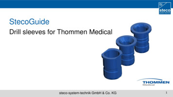
4.ImplantationESSENTIALSEach implant package comes with three patientlabels. These labels are used in order to ensurethe traceability of the implants, as well as torelay the pertinent information of manufacturer,implant type and implant dimensions to therestorative clinician. These labels should beused in the practice for documentation and forthe patient passport.Thommen implants are sterile and are double-packed. Remove the implant in the sterile packagingand protective packaging from the cardboard boxand check for damage. Sterility is not guaranteed ifimplants are removed from damaged packaging orif implants are not used immediately after openingthe packaging.Follow the directions for maintaining an asepticproduct when removing the implant container outof the sterile packaging and the implant from theimplant container.APLIQUIQ – Designed for function.CatridgeThe cartridge contains theconditioning agent and issealed with a foil seal.BodyThe body is the central partof APLIQUIQ and protects the drymounted implant during storageand conditioning.ReservoirThe integrated reservoir catchesthe liquid after the conditioningprocess and prevents spillage.Healing capThe healing cap is safely embedded inthe rotating lid and can be removed onlyin the half-open position of the lid.LidThe rotating lid offers accessto the implant and covers the passage tothe reservoir in its fully open position.ImplantImplants are mounted on the insertionaid.WingletsWhen the winglets are pressed togetherthe clamping force on the insertion aid isreleased and the implant can be removedeasily. Thommen Medical17
SURFACE CONDITIONING WITH APLIQUIQConditioning of the implant is performed immediately before implantationusing the APLIQUIQ conditioning system. Remove the APLIQUIQ containerfrom the sterile packaging and activate by pressing the liquid-filled cartridgeinto the applicator body.Hold the applicator vertically with the cartridge upwards and shake vigorously at least five times. This conditioning process is the only way to producethe superhydrophilic INICELL surface.5 Afterwards hold APLIQUIQ horizontally and allow the conditioning agent toflow into the integrated reservoir.After the conditioning process, the surface properties of INICELL are maintained throughout the patient’s treatment time. The liquid must not be usedany further.REMOVING THE IMPLANT FROM THE APLIQUIQ CONTAINERAfter conditioning, remove the rubber cap on the rear of the applicator in thedirection of the arrow. Place the applicator horizontally on a firm surface.Rotate the lid to an unobstructed view of the implant and the insertion aid.Ensure that the implant is entirely conditioned and wet.Place the MONO insertion device (the adapter for the contra-angle handpiece)on the insertion aid. Apply light pressure to the lateral wings on the applicator to release the clamping force of the implant retainer. Once the retainerhas opened, carefully remove the implant from APLIQUIQ without turning it.The implant can be inserted manually (using the MONO insertion device) ormechanically (with the handpiece adapter) (see page 20–21).For implants that are not packaged in APLIQIQ, proceed similarly and remove using the MONO insertion device or the adapter for the contra-anglehandpiece (see below).18 Thommen Medical
Standard packaging for implantsHealing cap (below lid)Implant containerInsertion aidREMOVE THE IMPLANT FROM THE STANDARD PACKAGINGHold implant container as shown. Swivel the lid until resistance is felt.Place the insertion device on the insertion aid and carefully remove the implant from the implant container without rotating the implant. Thommen Medical19
MANUAL IMPLANT INSERTIONFor manual implant insertion of Thommen implants with the MONO torqueratchet, there are two insertion devices: the MONO insertion device, short,and the MONO insertion device, long.Both instruments feature an internal hexagon for accepting the pre-mountedinsertion aid on the implant.Without the insertion aid (due to being unsterile or loss), work can be donewith the adapter for handpiece, one-piece (see page 37).Insert the implant into the prepared implant bed. Manually screw in the implant with the MONO insertion device to the point where the implant is seatedfirmly in the bone.AScrew inAfterwards continue working with the MONO torque ratchet. Place the torqueratchet in the direction of the arrow as far as the stop on the ratchet body ofthe MONO insertion device.Do not force the ratchet onto the insertion device. The torque ratchet shouldsimply slide over the ratchet body of the MONO instrument. If this is not thecase, the parts are not aligned correctly. Realign accordingly and check fordamage.BUnscrewThe torque ratchet is labeled on one side with “IN” (A), and on the other sidewith “OUT” (B). The arrow on the ratchet indicates the direction for tightening or loosening. For insertion or tightening, the side marked “IN” pointsupward. For removal or loosening, the word “OUT” points upward for unscrewing.See page 35 for further information on using the torque ratchet. To achieveadditional safety when using MONO instruments, the MONO circlip can beoptionally used.20 Thommen Medical
Screw in the implant with slow movements of the ratchet. To screw in, guidethe ratchet on the rigid arm (A) as shown in the picture.352515AThe ratchet can be guided either with the finger on the finger rest (B) or theguide key (C).C3525150BTo display the torque, the flexible section of the ratchet, the bending rod (D),can be used.DMECHANICAL IMPLANT INSERTIONTo mechanically insert the implant, the handpiece adapter comes in twolengths.Important: Only supported handpieces must be used for mechanical insertion under power.Push the handpiece with inserted handpiece adapter over the insertion aiduntil it stops against the APLIQUIQ implant container.While screwing in the implant under power, always exert a slight axialpressure on the handpiece. This ensures that the insertion aid completelyengages with the internal hexagon of the implant and can be removed without any problems after implantation.The maximum rotation speed is 15 rpm. Thommen Medical21
ALIGNMENT OF THE INTERNAL HEXAGONABThe internal hexagon needs to be perfectly aligned if angled abutments(e.g. SPI EASY or SPI VARIO) are to be used in the restoration.The devices for screwing in the implants – MONO insertion device (A),Adapter for handpiece (B) and Adapter for handpiece (one-piece) – aremarked with six dots. These dots are used for the alignment of the implant, marking the position of the corners of the internal hexagon and thesuperstructure.To insure adequate access to the abutment screw channel, we recommendaligning one of the points in a facial/labial direction.For additional information, see the instructions of use for the respectiveabutments.REMOVING THE INSERTION AIDTake the insertion aid (A) out of the implant in an axial direction.A22 Thommen MedicalImportant: If there is high insertion torque after screwing in the implant withthe adapter, make a short counter-movement (counter-clockwise). This facilitatesremoving the insertion aid.
PLACEMENT OF HEALING CAP (GINGIVA FORMER)/USE OF MONO SCREWDRIVERBefore you place the healing cap, the interior of the implant needs to beclean and free of blood.The fit of the implant-abutment connection can be considerably impaired if debris or any material (such as bone substitute material) creates an obstructionbetween the implant and the healing cap, gingiva former or abutment. Thecorrect seating of each prosthetic part must be precisely checked, especiallywhen using very viscous pastes. Ensure that small items are not aspirated.Twist the cover of the APLIQUIQ container to expose the healing cap. Engagethe healing cap with a M
Small-diameter implants of the Thommen Implant System are platform 3.5 mm. Indications, contraindications and requirements for implants of the Thommen Implant System with a diameter less than platform 3.5 mm can be found in the corresponding instructions for use. In general: · Reduced-diameter implants should only be used where bone volume