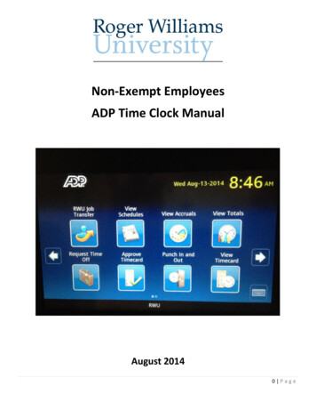
Transcription
Clock Talk LIVE Schedule – Presentation will begin shortlyTuesday, Sept 15thIEEE 1588 Timing Solutions for Non-Telecom ApplicationsTuesday, Sept 29thClock Jitter Demystified and Jitter Requirements for 56/112 SerDesTuesday, Oct 13thDesign Considerations When Selecting a XO/VCXO Clock Referencefor 56G/112G SerDesTuesday, Oct 27thStop Guessing, Use Silicon Labs Timing Tools to Build Your Clock TreeTuesday, Nov 10thOptimize Timing Solutions for High-Speed FPGA and ApplicationProcessor DesignsTuesday, Nov 17thPCIe Gen 4/5/6 Specifications and Jitter Measurement ExplainedTuesday, Dec 1st1Timing Solutions for 5G O-RAN SystemsTuesday, Jan 12thAEC-Q100 Timing Products for Automotive ApplicationsTuesday, Jan 26thTiming Solutions for Open-Compute SystemsRespond to the poll to enter towin a 50 Amazon gift cardRegister for the series and find pastrecorded sessions at:https://www.silabs.com/clock-talk
WELCOMEWELCOMESILICON LABS LIVEInternetInfrastructureandAEC-Q100Timing ProductsIndustrialAutomationTech TalksFor AutomotiveApplicationsKyle BeckmeyerJanuary 12, 20212
Agenda Automotive Trends Driving Larger, More Complex Clock Trees Introduction To Silicon-Based Timing Solutions Health Monitoring, Fault Detection, and Redundancy Overcoming Emissions Challenges, CISPR25 Analysis Product Information and Design Resources3
Agenda Automotive Trends Driving Larger, More Complex Clock Trees Introduction To Silicon-Based Timing Solutions Health Monitoring, Fault Detection, and Redundancy Overcoming Emissions Challenges, CISPR25 Analysis Product Information and Design Resources4
Automotive Trends Driving Larger, More Complex Clock Trees5
Rapid Increase In Technology AdoptionL2 /L3 ADAS and Automated DrivingCentralized In-Vehicle-NetworkingLeaps in Data Aggregation,transfer, and ProcessingECU ConsolidationV2x ConnectivityEnabled Through:ADCULidar System(s)Camera/VisionSystemsNetworking GatewayLong Range RadarArticulatingRadarShort/MidRange RadarADAS ECU6 High BandwidthProcessors/SoCs/FPGAs Automotive Ethernet High Speed PCIe Data Bus Health Monitoring, faultdetection, and Redundancy
Increasingly Complex Clock RequirementsN E T W O R K I N G G AT E W AY S High BW SoC/Processor 100M/1G/2.5G/10GbE PCIe Gen3/4/57A D A S / A U T O M AT E D D R I V I N G High BW CPU/FPGA PCIe Gen3/4/5 and/or NVLink 100M/2.5G/10GbED I G I TA L C O C K P I T / I V I High BW CPU/ProcessorAudio DSPEthernet ConnectivityPCIe Gen3/4
Increasingly Complex Clock Trees PCI-Express Gen3/4/5 reference clocks 100MHz HCSL RMS Phase Jitter 500fs RMS 28G SerDes reference clocks (CPU/SoC/FPGA) 125MHz LVDS RMS Phase Jitter 500fs RMS IEEE 802.3bp, 802.3bw, 802.3ch, 10GbE 25MHz / 50MHz LVCMOS, 1ps RMS 125 / 156.25MHz LVDS, as low as 300fs RMS USB, memory, other system functions 24 / 48MHz LVCMOS 66.66MHz LVCMOS 25MHz LVCMOSDifferential reference clock neededSingle-ended reference clock needed8 27MHz LVCMOS
Negative Side Effects Of Adding More Quartz Quartz crystals and oscillators are susceptible toshock and vibration effects High failure (FIT) rates, low reliability Supply constraints, long lead timesExisting SolutionSilicon LabsCrystal FIT rate7 x 1.43 10.011 x 1.43 1.43Oscillator FIT rate3 x 4.77 14.31IC FIT rate91 x 1.6 1.6 Migrating to a silicon timing solution reduces pointsof failure, decreases DPPM, and provides numerousother features and benefits Clock tree example: 7 crystals1 x 1.6 1.6Total FIT rate25.923.03DPPM/yr22.72.6 3 differential oscillators 1 differential fanout buffer
Silicon-Based Solution AdvantagesLegacy ApproachSilicon Labs SolutionBenefits Over Quartz Integration of up to 12 LVCMOS/Differential clocks Up to 10x increase in reliability/FIT Any-frequency, Any-Output programmability Reduced cost, Improved phase jitter performance Configurable outputs, multi-profile capabilities Hardware pin control functions Health monitoring, fault detection, redundancy Spread spectrum, signal integrity tuning, etc In-system I2C programmability Configurable output format drivers Used on common platform reference designs
AEC-Q100 Timing Portfolio Introduction11
AEC-Q100 Qualified, Automotive Grade 2 Timing Product Family12C L O C K G E N E R ATO R SCLOCK BUFFERSPCIE CLOCKSPCIE BUFFERS6/8/12-Output Options230fs RMS Phase JitterCustom Programmable2/4/8/10-Output Options120fs RMS Additive JitterCustom Programmable4/8-Output OptionsPCIe Gen1/2/3/4/54/8-Output OptionsPCIe Gen1/2/3/4/5Clock Tree ConsolidationSmartClockTM FeaturesLoss of Signal (LOS) MonitorLevel/Format Translation85/100Ω Internal TerminationSpread Spectrum Modulation85/100Ω Internal TerminationLoss of Signal (LOS) Monitor
Si5332-AM Any-Frequency Clock GeneratorsNo. of ClockOutputsInputFrequencyOutputFrequency6 / 8 / 1210 to170 MHz10 to 333MHzPhaseJitter230# ControlPinsPackage5/7/732-QFN40-QFN48-QFN Generates any mix of output frequencies/formats Low phase jitter 190 fs RMS (integer) 60% lower than competing solutions 250 fs RMS (fractional) HCSL, LVDS, LVPECL, LVCMOS formats PCIe Gen1/2/3/4/5 compliant Integrated LDOs for high PSNR, simplifies external power filtering User-configurable HW input pins Frequency select, SSC, OE control, Loss of Signal (LOS) Two independent SSCG domains (down/center) Programmable using ClockBuilder Pro software utility
PCIe Gen1/2/3/4/5 Clock Generators & BuffersDevicePCIe ClockInputOutputPCIeVoltageOutputs Frequency Frequency Gen4 JitterSi5225xClocks4/825 MHz100, 133,200 MHz200 fs1.8-3.3 V32-QFN40-QFNSi5325xBuffers4/8100 MHz100 MHz36 fsAdditive1.8-3.3 V32-QFN40-QFN Fully compliant with PCIe Gen 1/2/3/4/5 Clocks: 200 fs Gen4 RMS phase jitter Buffers: 40 fs Gen4 Additive RMS phase jitter HCSL drivers with integrated termination Selectable 85/100 Ω impedance Spread spectrum for EMI reduction Individual output enable pins Dual input option for redundancy14Package
Si5335x Clock BuffersFamilyTypeSi5335xAFixed# of Clock FrequencyOutputs RangeOutputFormatLVCMOS,10 toLVPECL4 / 8 /10333 MHzLVDSCustomHCSLSi5335xB(CBPro)AdditiveVoltage PackageJitter110 fs32-QFN1.8-3.3 V 40-QFN48-QFN Single-ended and differential input/outputs Ultra-low additive jitter (120 fs RMS) Individual output enable pins Customize through ClockBuilder Pro Voltage translation Individually programmable output drivers (format translation) Output dividers (1-63) Loss of Signal (LOS)15
Health Monitoring, Fault Detection, Redundancy16
New Si5332-AM SmartClockTM Features Helps Meet Functional Safety Goals SmartClockTM features: Primary/secondary redundant input sources Loss of Reference fault monitoring Fast OOF fault monitoring Backup redundant input source Input reference selection AlwaysON mode provides outputs in the event of faults Test mode to ensure health monitoring block isoperating correctly17
New Si5118-AM SmartClock Synthesizer For system designs where reference clocks aregenerated by an SoC/FPGA Health monitoring and fault detection ofreference clocks needed for functional safetyblocks Primary input source and redundant backup localreference of the same frequency 16-50MHz frequency range Programmable output driver formats Frequency health monitoring Fast OOF fault signal output CLK SEL[1:0] input pins to migrate to backup Test mode to ensure health monitoring block isoperating correctly AlwaysON mode provides outputs in the event offaults18
Overcoming Emissions Challenges19
How To Optimize Clock Tree DesignSignal LayerGNDPlanesGND LayerClock (pos) traceClock (neg) traceGND Stitching viaGND LayerGND PlaneStitching ViasClock (pos) traceClock (neg) traceGND Stitching viaGND PlaneClocks routed as impedance controlled100 ohm differential signal20Stripline layerstackup Complementary LVCMOS output drivers 85/100Ω impedance controlled routing Route as a differential pair to endpoint Stripline clock trace techniques Terminate true to endpoint Avoid 90o angles, use 45o angles instead Terminate complement to ground viacapacitor of same value as endpoint Add stitching vias Please reference AN1237 for more details
Si5332 Auto-EVB Developed to fit inside SiLabs radio head unit chassis Performed CISPR-25, Class4, EMI testing at PTI Labs in AustinRear ViewFront ViewSide/Oblique ViewTop/Cover Off ViewSi5332-AM2 Auto-EVBSi5332-AM2 Device21
Si5332 Auto-EVB PCB Layout: Clock LayersStriplineClocks22
Frequency Plans Si5332-AM2 used following clock profiles for EMI testing Commonly used frequencies in automotive Frequency plans consisting of single-ended, and/or differential outputsSi5332 Profile #123Si5332 Profile #2Outputs:OUT0: 20 MHz LVCMOS Single ( ) 3.3 V 50 OhmsOEB INPUT7 (P37)OUT1: 25 MHz LVCMOS Single ( ) 3.3 V 50 OhmsOEB INPUT7 (P37)Delay - 70psOUT2: 38.4 MHz LVCMOS Single ( ) 3.3 V 50 OhmsOEB INPUT7 (P37)OUT3: UnusedOUT4: 40 MHz LVCMOS Single ( ) 3.3 V 50 OhmsOEB INPUT7 (P37)Delay - 140psOUT5: UnusedOUT6: 48 MHz LVCMOS Single ( ) 3.3 V 50 OhmsOEB INPUT7 (P37)Delay - 210psOUT7: UnusedOutputs:OUT0: 20 MHz LVCMOS (comp) 3.3 V 50 OhmsOEB INPUT7 (P37)OUT1: 25 MHz LVCMOS (comp) 3.3 V 50 OhmsOEB INPUT7 (P37)Delay - 70psOUT2: 38.4 MHz LVCMOS (comp) 3.3 V 50 OhmsOEB INPUT7 (P37)OUT3: UnusedOUT4: 40 MHz LVCMOS (comp) 3.3 V 50 OhmsOEB INPUT7 (P37)Delay - 140psOUT5: UnusedOUT6: 48 MHz LVCMOS (comp) 3.3 V 50 OhmsOEB INPUT7 (P37)Delay - 210psOUT7: UnusedFrequency Plan Fpfd 25 MHzFvco 2.4 GHz (4.8 GHz VCO)Frequency Plan Fpfd 25 MHzFvco 2.4 GHz (4.8 GHz VCO)Si5332 Profile #3Outputs:OUT0: 100 MHz LVDS Slow 3.3 VOUT1: 108 MHz LVDS Slow 3.3 VOUT2: 125 MHz LVDS Slow 3.3 VOUT3: UnusedOUT4: 50 MHz LVDS Slow 3.3 VOUT5: 25 MHz LVCMOS (comp) 3.3 V 50 OhmsOUT6: 26 MHz LVCMOS (comp) 3.3 V 50 OhmsOUT7: UnusedFrequency Planner Overrides Fvco Min: 2.5 GHzFrequency Plan Fpfd 25 MHzFvco 2.5 GHz (5.0 GHz VCO)
Si5332 EMI Testing DUT PicsTop Open24Top Closed
CISPR Testing CISPR25-Class4 Tested at PTI in Austin Multiple clock tree configurations tested Positive, passing results Comprehensive testing data available CISPR25-Class5 Tested at Elite Engineering, Chicago Multiple clock tree configurations tested Positive, passing results Comprehensive testing data available25
Band 1, Vertical Antenna Test Results Chassis Top Closed, Profile #3 150kHz to 30MHz26
Band 2, Vertical Antenna Test Results Chassis Top Closed, Profile #3 30MHz to 200MHz27
Band 3, Vertical Antenna Test Results Chassis top closed, profile #3 200 MHz – 1 GHz Band28
Band 4, Vertical Antenna Test Results Chassis top closed, Profile #3 1 GHz – 2.5 GHz (plot from CSV data)29
AN1237: Best Practices for Automotive Clock Tree Design Route all clocks using strip line techniques Use 45 angles, avoid 90 angles Use complementary LVCMOS output drivers for LVCMOS clocks Route the differential pair all the way to the endpoint Route one side into the endpoint Terminate the other side as close to the endpoint as possible usingcapacitor to ground Use impedance controlled routing for all clocks Use stitching vias to connect ground planes along clock path Keep other signals away from clock traces, use isolation grounds ifneeded30
Design Resources and Product Information31
Design ToolsCLOCKBUILDER PRO 32Configuration file development toolOptimizes clock output layoutPerforms design rule checksPower consumption estimatorAssigns orderable part numbersE VA L U AT I O N B O A R D S 6/8/12-Output Si5332-AM EVBsSi52254 PCIe Clock EVBSi53254 PCIe Buffer EVBSi53350 Clock Buffer EVBCBProg-Dongle Field ProgrammerPCIE CLOCK JITTER TOOL Greatly simplifies PCIe clock jittermeasurements Simply upload a waveform file PCIe Gen1/2/3/4/5 Filters Easy-to-read results summary
What’s On The Web Application web pages Design tools Application notes White papers Datasheets Family reference manuals Schematic symbols Technical Support Portal33
Summary Increased adoption of higher-BW platforms More complex clock trees Higher precision performance requirements Silicon-based AEC-Q100 solutions ideally suited to replace quartz consolidation, performance, reliability benefits over quartz Advanced features help simplify your design Health monitoring and fault detection OE, spread spectrum, signal integrity tuning Complementary LVCMOS drivers reduce emissions As a market leader in timing, Silicon Labs is committed to automotive34
Tuesday, Jan 12th AEC-Q100 Timing Products for Automotive Applications. Tuesday, Jan 26th Timing Solutions for Open-Compute Systems. 1. Register for the series and