Transcription
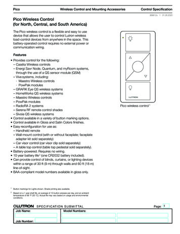
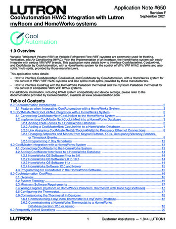
Guestroom Control UnitmyRoomControl Interfaces369708j 1 03.31.21The myRoom Plus Guestroom Control Unit(s) canintegrate with myRoom Vue and third-party systemsvia the onboard Ethernet link with additional licenses.Examples include Property Management Systems(PMS), Central Electronic Locking Systems (CELS) andBuilding Management Systems (BMS).2.0 A / L1, L224 – 36 V-FD/Col250 mAPWRmyRoomGCU-HOSP24 – 36 VIEC PELV / SELV / NECR Class 2www.lutron.com/qslutron.comModel NumbersRJ45Con/ActRJ45FD/ColP2 1COML15 4 3L2Lutron myRoom Plus Guestroom Control Unitscoordinate lighting, shades / draperies, andtemperature control in a hotel guestroom. These canbe automated for guest comfort when the roombecomes occupied and for energy savings when theroom is vacant.Con/ActmyRoom Plus Guestroom Control Unit1.844.LUTRON1 44.(0)20.7680.4481DMUXV MUXCOM1 2 3 4 5DQS L2QS L1L1L1L1 TX /RXL2L2 TX /RXMUX1 Link Control UnitMUXGCU-HOSP-1PWRERRL1V 2 Link Control UnitCOMGCU-HOSP1 2 3 4 5GCU-HOSP shown Job Name:Job Number:S P E C I F I C AT I O N S U B M I T TA LModel Numbers:Page1
Guestroom Control UnitmyRoomControl Interfaces369708j 2 03.31.21SpecificationsRegulatory Approvals RoHS CompliantPower Supply Wire Type 18 AWG (0.75 mm2) Complies with UL508Link Capacities QS Wired Device Link: maximum 50 devices, 50zones, 50 occupancy sensors, and 100 switch legs(ballasts, drivers, and interfaces). Complies with CSA-C22.2 No. 14 Complies with IEC / EN 60669 NOMPower GCU-HOSP- Processor (P): 24 – 36 V- 250 mA- Links (L1/L2): 24 – 36 V- 2 A per link GCU-HOSP-1- Processor (P): 24 – 36 V- 250 mATypical Power Consumption 5 W; 8 Power Draw Units (PDUs)Environment Ambient Temperature Operating Range:32 F to 104 F (0 C to 40 C) Unit generates heat, maximum 24 BTU/hr Relative humidity: 0% to 90% non-condensing For indoor use only.Cooling Method Passive coolingInternal Timeclock 1 minute per yearPower Failure Memory System data stored in non-volatile memory. Systemprogramming retention for 10 years.Miswire Protection All terminal block inputs are over-voltage and miswireprotected against wire reversals and shorts. QS RF Link: maximum 50 devices and 100 zones. 230 V Thermostat Control Link: maximum 32 roomthermostats (LR-HVAC-230-S). Power Panel Link - 16 addresses / 256 zonesConnections GCU-HOSP- Two 5-pin, removable terminal blocks* for Link 1 andLink 2 communications.- One 5-pin, removable terminal block* for PowerInput. GCU-HOSP-1- One 5-pin, removable terminal block* for PowerInput / Link 1 communications.Communication Links Each Lutron myRoom Plus Guestroom Control Unithas up to three communication links:– Link 1 and Link 2 (GCU-HOSP only): Lutron QSwired device link, QS RF link, or thermostat controllink.– Ethernet:º GCU-HOSP — 2 Ethernet jacks for systemstart-up and PMS / BMS / CELS integration. Up to2 GCU-HOSP processors can be daisy chainedfor very large guestrooms.º GCU-HOSP-1 — 1 Ethernet jack for systemstart-up and PMS / BMS / CELS integration. Canonly be daisy chained via Ethernet to oneGCU-HOSP processor.Communications Link Wire Type Two pairs: one pair 18 AWG (0.75 mm2), one pair18 AWG to 22 AWG (0.75 mm2 to 0.34 mm2) twisted,shielded: IEC PELV / NECR Class 2 cable Total wire length for each link must not exceed 500 ft(152.4 m)* Job Name:Job Number:S P E C I F I C AT I O N S U B M I T TA LModel Numbers:Each terminal will accept up to two 18 AWG (0.75 mm2) wires.Page2
Guestroom Control UnitmyRoomControl Interfaces369708j 3 03.31.21Specifications (continued)System Capabilities Lutron QS Link allows control and programming of:– DIN rail power modules– Palladiom and seeTouch QS keypads– Palladiom QS thermostat– Pico wireless controls (through QS sensor module)– Sivoia QS motorized shades / draperies– Interfaces for door sensors, window sensors, roomchimes, and privacy and service controls 230 V thermostat control link allows control ofLutron room thermostat (LR-HVAC-230-S). Keypad buttons can be programmed to toggle lights,select room scenes, or raise and lower lighting orshades / draperies. Conditional logic can be programmed to selectdifferent actions based on inputs (e.g., time of day). Lutron myRoom Plus Guestroom Control Unit caninterface with the hotel Property Management System(PMS) via a wired Ethernet hotel network connection.A software license is required. For example,LMR-OPERA-PR is required to interface with MicrosROperaT PMS. Lutron myRoom Plus Guestroom Control Unit caninterface with the Hotel Service Optimization System(HotSOS) via a wired Ethernet hotel networkconnection. Software license LMR-HOTSOS-PR isrequired for a Newmarket HotSOS interface. Lutron myRoom Plus Guestroom Control Unit caninterface with the hotel Building Management System(BMS) via a wired Ethernet hotel network connection.Software license LMR-BAC-PR required for nativeBACnet interface. BACnet interface allows BMS to monitor and controlroom lighting, shades / draperies, temperature, roomoccupancy and vacancy status, and identify systemfaults. Lighting and HVAC load schedule data can beprogrammed at start-up. This data is used to calculateroom lighting and HVAC power usage, and is availableto the hotel BMS for logging and reporting via thenative BACnet interface. myRoom Vue can provide a powerful softwareinterface to control, configure, monitor, analyze andreport on the myRoom Plus system. This requireslicense LMR-MYRMVUE-PR. Lutron myRoom Plus Guestroom Control Unit caninterface with the hotel Central Electronic Lock System(CELS) via a wired Ethernet hotel network connection.A software license is required. For example,LMR-SAFLOK-PR, LMR-SALTO-PR, orLMR-VINGCARD-PR is required depending on whichCELS vendor is being used (KABAR Saflok, SALTOR,or ASSA ABLOY VingCardR interface). Job Name:Job Number:S P E C I F I C AT I O N S U B M I T TA LModel Numbers:Page3
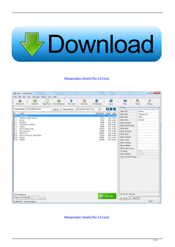
Guestroom Control UnitmyRoomControl Interfaces369708j 4 03.31.21DimensionsDimensions shown as: in (mm)GCU-HOSPTop View2.0 A / L1, L224 – 36 V-RJ45Con/ActFD/ColFD/ColCon/ActRJ45FD/Col2502 mA1RJ45Con/ActFD/ColPCOMRJ45COML1L1L232.05 A /4L1, L224 – 36 VPWR2 1PL25 4 3Side ViewCon/ActFront View250 mAPWRmyRoomGCU-HOSPmyRoom24 – 36 V-GCU-HOSPIECPELV / SELV / NECR Class 224 – 36 V-www.lutron.com/qsIEC PELV / SELV / NECR Class .LUTRON1 44.(0)20.7680.4481lutron.comPWRERRL1L1 PWRERRL1L1 TX L1/RXL2 L1L1TX /RXQS L2 L2L1 TX /RXL21 L22 3 L24 TX5/RXQS1.844.LUTRON1DDMUXMUXV MUXMUXV 1 2 3 4 5COMDMUXMUX4 5DV MUXCOM1 L12 3QSMUXV COMQS L1COM 44.(0)20.7680.44811 2 3 4 54.27(108) Job Name:Job Number:1.06(27)S P E C I F I C AT I O N S U B M I T TA LModel Numbers:Page4
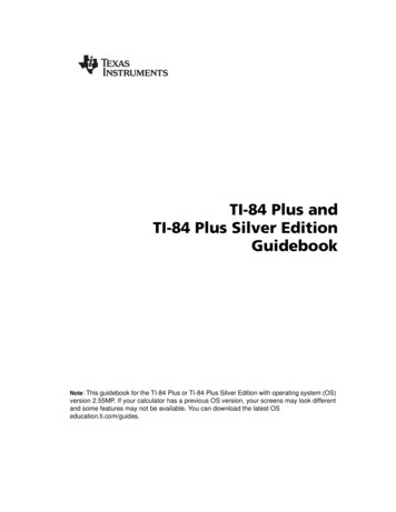
Guestroom Control UnitmyRoomControl Interfaces369708j 5 03.31.21DimensionsDimensions shown as: in (mm)GCU-HOSP-1Top ViewSide ViewFD/ColRJ45Con/ActFront ViewmyRoomGCU-HOSP-124 – 36 VIEC PELV / SELV / NECR Class 4.LUTRON1 44.(0)20.7680.4481PWRERRL1L1L1L1 TX /RXDV MUXMUXCOMQS L11 2 3 4 54.27(108) Job Name:Job Number:1.06(27)S P E C I F I C AT I O N S U B M I T TA LModel Numbers:Page5
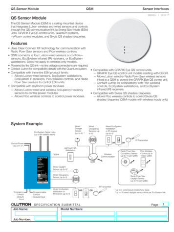
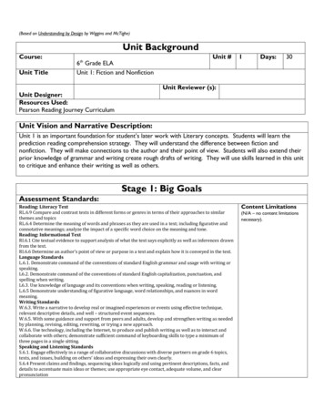
Guestroom Control UnitmyRoomControl Interfaces369708j 6 03.31.21MountingMount the myRoom Plus Guestroom Control Unit (GCU) in an enclosure according to national and local codes.The GCU is typically powered using the QSPS-DH-1-75 or MQSPS-DH-1-30 power supply. The GCU andenclosure must be mounted vertically due to thermal management. The figure below gives examples ofacceptable and unacceptable mounting.Ceiling1 2 3 4 5QS L21.844.LUTRON1 44.(0)20.7680.44811 2 3 4 5lutron.comwww.lutron.com/qsQS L1IEC PELV / SELV / NECR Class 224 – 36 V-GCU-HOSPmyRoomPWR2 15 4 3250 mA2 1RJ45RJ45D5 4 3MUX2.0 A / L1, L224 – 36 V-V PWRMUXL2COM2.0 A / L1, L224 – 36 V-GCU-HOSPmyRoomDPL1MUX250 mA24 – 36 V-MUXPWRERRL1L1L1L1 TX /RXL2L2 TX ron.com/qsIEC PELV / SELV / NECR Class 2COMV V COMMUXL2PL1COMCon/ActFD/ColCon/ActFD/Col1 2 3 4 51 2 3 4 5COM1.844.LUTRON1QS L2QS L1L1L1L1 TX /RXL2L2 TX /RXMUX UTRON1 44.(0)20.7680.4481COMCon/Actlutron.comV PWRERRL1L1L1L1 TX /RXL2L2 TX /RXwww.lutron.com/qsMUXFD/ColIEC PELV / SELV / NECR Class 2MUXQS L224 – 36 V-D1 2 3 4 5QS L1L21 2 3 4 5Con/ActV MUXCOMDGCU-HOSPMUXmyRoomCOMPWRV RJ45250 mAMUXRJ45MUX2.0 A / L1, L224 – 36 V-2 1D5 4 32.0 A / L1, L224 – 36 V-RJ45FD/ColCon/ActRJ45FD/ColP2 1COML1L25 4 3Con/ActFloor250 mAPWRmyRoomGCU-HOSP24 – 36 VIEC PELV / SELV / NECR Class 2www.lutron.com/qslutron.com1.844.LUTRON1 44.(0)20.7680.4481PWRERRL1 Job Name:Job Number:S P E C I F I C AT I O N S U B M I T TA LModel Numbers:DMUXMUXV DMUXV MUXCOM1 2 3 4 5COMQS L2QS L1L1L1L1 TX /RXL2L2 TX /RX1 2 3 4 5Page6
Guestroom Control UnitmyRoomControl Interfaces369708j 7 03.31.21Mounting (continued)LPower Supply 1,2QSPS-DH-1-75 orMQSPS-DH-1-30(up to 2)NL( ) N(-)120 - 240 VInput / Entrada / Entrée24 VOutput / Salida / SortieGuestroom Control Unit 1,2GCU-HOSP orGCU-HOSP-122.5 - 25 V OR2.0 A / L1, L224 – 36 V-System Interfaces /ColPL1L22 1COM5 4 3250 mAPWRmyRoommyRoomGCU-HOSPGCU-HOSP-124 – 36 V-24 – 36 V-IEC PELV / SELV / NECR Class 2IEC PELV / SELV / NECR Class .LUTRON11.844.LUTRON1 44.(0)20.7680.44811 2 3 4 5DCOMV DMUX1 2 3 4 5MUXCOMV QS L1L1L1L11 TX /RX/RXQS L1DMUXMUX1 2 3 4 5COMDMUXMUXV COML1L1L1 TX /RXL2L2 TX /RXQS L2QS L1PWRERRL1V PWRERRL1MUX 44.(0)20.7680.4481MUXlutron.com1 2 3 4 5LV16To AdditionalQS DevicesLocation for mounting QSWire Landing Board. 1QS-WLB(up to 4)CommonFrom Power SupplyV RJ45FD/ColCon/ActRJ45FD/ColPL1L22 1COM5 4 32.0 A / L1, L224 – 36 V-Con/Act(5) Ground(4) Red “L2” Link 2 Power(3) Red “L1” Link 1 Power(2) Red “P” Processor Power(1) Black “COM” Common25050 mAPWRmyRoomwww.lutron.com/qs2.0 A / L1, L21.844.LUTRON1 44.(0)20.7680.4481120 - 240 VInput / Entrada / Entrée3DV Guestroom Control Unit 1GCU-HOSP orGCU-HOSP-1Location for mounting QS Wire Landing Board. 1QS-WLB(up to 2)L-LV1421 2 3 4 5250 mAPower Supply 1QSPS-DH-1-75 orMQSPS-DH-1-30 322.5 - 25 V1MUXMUXDMUXV COM24 VOutput / Salida / SortieCOMQS L21 2 3 4 5MUXIEC PELV / NEC Class 2QS L1L( ) N(-)PWRERRL1L1L1L1 TX /RXL2L2 TX /RX2 1PL2IEC PELV / SELV / NECR Class 2lutron.comL15 4 324 – 36 V-COMGCU-HOSPAll components sold separately.Maximum of 2 Control Units / Interfaces allowed per enclosure.Requires mounting kit MQSPS-BRK. Job Name:Job Number:S P E C I F I C AT I O N S U B M I T TA LModel Numbers:Page7
Guestroom Control UnitmyRoomControl Interfaces369708j 8 03.31.21Adding Interfaces with the Low-Voltage Dual Accessory BracketIf the GCU cannot fit in the panel with other devices, the Low-Voltage Accessory Bracket (DIN-2CD-CGP2948)may be an acceptable option to mount the GCU over another GCU or interface. The DIN-2CD-CGP2948 is ametal bracket designed to stack two Lutron low-voltage devices in a single location. The bracket is installed underthe original device. This allows a second device to be install on top of the GCU. The second device is offset,allowing the LED indicators of the lower device to remain visible. The DIN-2CD-CGP2948 is only compatible withpanels that contain a low-voltage section. Sold separately. Contact Lutron Customer Service for ordering.DIN-2CD-CGP2948 contains the following:Mounting Bracket (1 pc)Instruction Sheet8-32 x 3/8 in screw(2 pcs)8-32 x 1/2 in screw(2 pcs)Mounting:8-32 x 3/8 inscrew (2 pcs)8-32 FlatWasher (4 pcs)8-32 x 1/2 inscrew (2 pcs) Job Name:Job Number:S P E C I F I C AT I O N S U B M I T TA LModel Numbers:Page8
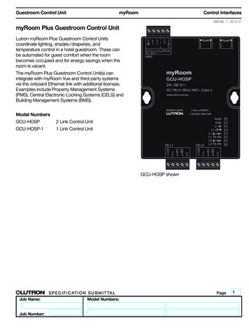
Guestroom Control UnitmyRoomControl Interfaces369708j 9 03.31.21System Diagram ExamplePalladiom QS keypadPalladiom QS keypadTo HVACcontrollerPalladiom QSthermostatPalladiom QSkeypadAlenaQS wireddrapery trackQS SensorModulePalladiom QSkeypadQS wiredconnection2.0 A / L1, L224 – 36 V-RJ45Con/ActRJ45FD/ColP2 1Con/ActL11L22 7 5 5 7 6 1 32 3COM0FD/ColCCO 25 4 3CCO 1CCO 5CCO 4StatusPGMON8 7 6 5 4 3 2 1CCO 3Wirelessoccupancysensor250 mAPWRQSE-IOmyRoom24 - 36 V- 100 mATMGCU-HOSPSELV /PELV /NECR Class 224 – 36 V-www.lutron.com/qsIEC PELV / SELV / NECR Class 2www.lutron.com/qslutron.com 1.800.523.9466 1.610.282.3800lutron.com1.844.LUTRON1 44.(0)20.7680.4481Load controllers(wired)To door contactTo door bellTo third-partycorridor plateTo receptaclecontrollerContactclosureinterfaceDV MUXPWRERRL1L1L1L1 TX /RXL2L2 TX /RXMUXV 1 2 3 4 5COMDMUXMUXCOMCOMCCO 5 NCCCO 5 NOCCO 4 NOCCO 3 NOCCO 4 NC3-4 COMCCO 2 NC5 COMCCI 2CCI 3CCO 2 NOQS L2QS L1CCI 4CCO 3 NCVCCI 5CCO 1 NCCCO 1 NO1-2 COMQSCOMMUXMUXV 4 3 2 1RR1A½ACCI 1V0-36 V0-36 V 1 2 3 4 5Guestroomcontrol unitPalladiomQS keypadProperty Management System(PMS)HotelNetworkBuilding Management System(BMS)Central Electronic Locking System(CELS)Third-Party IntegrationmyRoom Vue DashboardsLutron, Lutron, Palladiom, seeTouch, Pico, Sivoia, myRoom and Alena aare trademarks or registered trademarks of Lutron Electronics Co., Inc. in the USand/or other countries.All other product names, logos, and brands are property of their respective owners. Job Name:Job Number:S P E C I F I C AT I O N S U B M I T TA LModel Numbers:Page9
Mount the myRoom Plus Guestroom Control Unit (GCU) in an enclosure according to national and local codes. The GCU is typically powered using the QSPS-DH-1-75 or MQSPS-DH-1-30 power supply. The GCU and enclosure must be mounted vertically due to thermal management. The figure below gives examples of acceptable and unacceptable mounting. GCU-HOSP .