Transcription
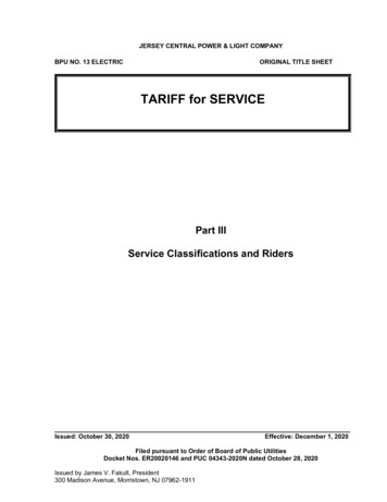
IMPROVING THE BUILT ENVIRONMENTSolar Domestic Water HeatingA Roof-Integrated EvaluationIn 2005, CARB began work with Dawn Solar Systems Inc. on a project to evaluate theperformance of Dawn’s roof-integrated solar water heating system. The key benefit of thesystem is integration and aesthetic appeal; looking at the home evaluated (Figure 1), one doesnot notice any evidence of solar collectors.Figure 1. The home in Litchfield, CT with roof-integrated solar thermal and electric systems.The south-facing roof of the home in Litchfield, CT actually consists of three active solarsystems. The main southern roof of the home (approximately 750 ft2) incorporates a solarthermal system for space and water heating. The southern shed dormer (250 ft2) supports botha thermal system (dedicated for domestic water heating) as well as a roof-integrated PV systemusing amorphous silicon laminates. Beneath the standing-seam metal roofs, the unglazedthermal collectors consist of cross-linked polyethylene (PEX) piping run in metal heat transferplates. A propylene glycol solution is circulated through the collectors and through heatexchangers in storage tanks in the basement.CARB did not participate in the design of the home or the energy systems, but as the home wasnearing completion CARB seized an opportunity to install instrumentation to monitorperformance of the solar systems. Over a 12-month period monitored (after all systems hadbeen commissioned), the solar thermal systems provided 38% of the domestic water heatingload and provided 2.0 MMBtu of space heating load (offsetting approximately 24 gallons ofpropane). The 1.4-kW solar electric system generated 1,809 kWh, providing 31% of the home’stotal electric load.Consor tium for A dvance d Re sidential Buil dingsSteven Winter Associate s, Inc.www.ca rb-swa .co m50 Wa shingt o n St . 6t h F l, No rwa lk , CT 068 54307 7th A ve. Ste. 1701, New York, NY 100011112 16t h St ., N W S t e . 240, Wa sh in gt on , D C 20036tel 203-857-0200 fax 203-857-0200tel 212-564-5800 fax 212-741-8673tel 202-628-6100 fax 202-393-5043
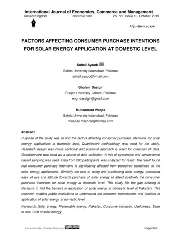
System DescriptionsThe solar systems in this home are designed to be very well integrated into the home’s roofsystem. From the outside, there is no visible evidence that solar thermal collectors exist on thesouth-facing roof, and the solar electric laminates (on the shed dormer) are very low-profile anddifficult to detect.Figure 2. The home during construction. Solar thermal and PV collectors have been installed onthe shed dormer. Metal roofing has not yet been installed over PEX tubing and heat transferpurlins on the main roof area.Above the roof deck and beneath the standing-seam metal roof, cross-linked polyethylene(PEX) tubing is plumbed through metal channels designed to hold the tubing in place whilefacilitating heat transfer. There are two separate solar thermal systems: the collector area forthe small system is the 250-ft2 area above the shed dormer on the southern roof; collection forthe large system is installed in the 750 ft2 of the main roof of the home (surrounding the dormer).The PEX pipes above the roof deck connect to manifolds in the conditioned attic of the home,and larger, insulated PEX pipes run from the attic manifolds to heat exchangers located instorage tanks in the basement.The storage tank for the smaller system is a 120-gallon potable water tank; the larger systemheats an unpressurized 300-gallon tank. Differential controllers sense the temperaturesbeneath the metal roofing as well as in the storage tanks; when the roof is substantially warmer,a 50% propylene glycol solution is circulated to transfer energy from the collectors to the tanks.The smaller solar thermal system provides heat for domestic water heating only; the largesystem can provide heat to domestic water or to the radiant floors. Home occupants usemanual valves to switch between the two uses of the larger system. On a domestic hot waterdraw, cold well water flows into the bottom of the smaller solar storage tank. From the top of thetank, preheated water exits and runs through a heat exchanger in the large solar tank (ifenabled). From the solar tank(s), preheated water enters the auxiliary water heater – an indirecttank heated by a condensing, propane-fired boiler.The roof of the shed dormer also supports UniSolar PV laminates. Each of the 12 standingseam roof panels contains a 116-Watt collector (for a total of 1,392 WattsDC,STC). The collectorsare wired together in series (beneath the ridge cap of the home) and connected to an inverterlocated in the basement.Consor tium for A dvance d Re sidential BuildingsSteven Winter Associate s, Inc.www.ca rb -swa .co m50 Wa sh in gt o n St . 6t h F l, No rwa lk , CT 068 54307 7th A ve. Ste. 1701, New York, NY 100011112 16t h St ., N W St e . 240, Wa sh in gt on , D C 20036tel 203-857-0200 fax 203-857-0200tel 212-564-5800 fax 212-741-8673tel 202-628-6100 fax 202-393-5043
Monitoring ParametersPerformance of the solar thermal system was monitored by measuring several temperaturesand fluid flow rates. CARB installed thermistors to measure the following temperatures: Outdoor air (in an aspirated radiation shield) Twenty collector temperatures (beneath the roof and above the roof deck where solarcollector piping is run) Cold water from the well Preheated DHW leaving the small solar tank Preheated DWH leaving the heat exchanger in large solar tank DHW leaving the auxiliary heater (going to DHW loads) Solar tank temperatures (near the top of tanks) Glycol solution exiting each tank heat exchanger (running to the attic manifolds) Glycol solution at each attic manifold (running out to the roof collectors) Heated glycol solution at each attic manifold (coming in from the collectors) Heated glycol solution entering each tank heat exchanger (coming from attic manifolds)Using turbine meters, three liquid flow rates in this system were measured: Domestic hot water Glycol solution in each solar collection loopTo monitor the electric systems, Watt-hour transducers were installed to measure PVgeneration and net electricity consumption for the home.In addition, a pyranometer was installed on the roof to measure global horizontal radiation. Allsensors were connected to a Campbell Scientific CR10X datalogger, and the datalogger wasconnected to a modem that allowed data to be collected remotely.System PerformanceBecause the plumbing systems and controls were fairly complicated, the system was notoperating as designed until approximately 18 months after installation. The integration of spaceheating performance was especially complicated. Before the controls were repaired and thesystem was fully commissioned, it was rare for there to be any solar contribution to spaceheating. The system was fully operational in April of 2007, so data from the first twelve monthsof full operation are presented here (May 2007 – April 2008).Domestic Water HeatingOver this 12-month period, the solar thermal systems provided 38% of domestic water heatingenergy (with an average consumption of 35.7 gallons of hot water per day). The total energycontributed to water heating over this period was 2.95 MMBtu. Using a simple effectiveefficiency of the indirect water heater of 80% (CARB did not measure performance of theindirect water heater), the solar system offset approximately 40 gallons of propane. Figure 3shows that the solar contribution is much greater in the summer months than in winter months –as expected. It’s also worth noting that the smaller solar system (250 ft2 vs. 750 ft2) provides85% of the total solar contribution.Consor tium for A dvance d Re sidential BuildingsSteven Winter Associate s, Inc.www.ca rb -swa .co m50 Wa sh in gt o n St . 6t h F l, No rwa lk , CT 068 54307 7th A ve. Ste. 1701, New York, NY 100011112 16t h St ., N W St e . 240, Wa sh in gt on , D C 20036tel 203-857-0200 fax 203-857-0200tel 212-564-5800 fax 212-741-8673tel 202-628-6100 fax 202-393-5043
Figure 3. Average daily domestic water heating energy by month for the first full year monitoredwhere all systems were operational.Space HeatingThe primary function of the larger solar thermal system (the steeper, main part of the home’sroof covering approximately 750 ft2) is to provide space heating through the radiant floor heatingsystem. The system is designed and installed so that the home owner must manually adjustvalves to direct heat either to the domestic water stream or to the radiant floor. Since April of2007 – when the system became fully operational – it appears that the owner has made theappropriate changes (near the equinoxes) to the valves. Figure 4 shows the monthly solarcontributions to space heating.Monthly Heat to Radiant Floor [kBtu]Solar Energy toRadiant Floor [kBtu]700600500400300200100May-0Ju 7n07Jul-0Au 7g0Se 7p0O 7ct-0N 7ov-0D 7ec-0Ja 7n0Fe 8b0M 8ar-0Ap 8r- 0M 8ay-0Ju 8n08Jul-0Au 8g0Se 8p0O 8ct-080MonthFigure 4. Summary of monthly solar contributions to radiant floor heating. Effective heating onlyoccurs during swing seasons – there is no solar space heating from December - February.Consor tium for A dvance d Re sidential BuildingsSteven Winter Associate s, Inc.www.ca rb -swa .co m50 Wa sh in gt o n St . 6t h F l, No rwa lk , CT 068 54307 7th A ve. Ste. 1701, New York, NY 100011112 16t h St ., N W St e . 240, Wa sh in gt on , D C 20036tel 203-857-0200 fax 203-857-0200tel 212-564-5800 fax 212-741-8673tel 202-628-6100 fax 202-393-5043
PV GenerationThe solar electric system on the home worked quite well. The roof faces within 10 of duesouth, and there is virtually no shading of the collectors. Over the twelve months from May2007 through April 2008, the system generated 1,809 kWh. This equates to normalized annualgeneration of 1,299 kWhAC/kWDC,STC. This is excellent performance for New England. FromSWA’s experience monitoring and evaluating PV systems in the northeast, generation above1,100 kWhAC/kWDC,STC is above the average for typical residential PV systems. Figure 5 showsthe average daily generation of the system by month.PV GenerationAverage Daily PVGeneration 08Feb08Mar-08Apr-0807n-JuMay-070Figure 5. Average daily PV generation by month of the 1.4-kW PV system.System BenefitsFrom CARB’s monitoring and research, a “typical” solar domestic water heating system (e.g. 80ft2 of flat-plate collector with 110 gallons of storage) will provide solar fractions of 60-80% in aresidence with average hot water consumption. This system provided only 38% of the domesticwater heating load. This is discussed more in the “Gaps and Lessons Learned” section below.Aside from energy savings, the key whole-building benefit of the system was the integration.Aesthetics is always subjective, but this system truly is integrated. There is no outward, visibleevidence that the home contains a solar thermal system.Cost AdvantageThe costs of these solar thermal systems were not made public. One estimate from themanufacturer, however, is that a “typical” roof-integrated solar thermal system used for domesticwater heating only will cost 50% more than a “conventional” solar thermal system. In thiscomparison, a “typical” Dawn Solar system would include approximately 400 ft2 of collector and110 gallons of storage; a “conventional” solar thermal system would feature approximately 80 ft2of flat plate collector with 110 gallons of storage.As the system evaluated here contained two solar thermal systems as well as complex controlsand plumbing for integration with both domestic water and space heating systems, this 50%incremental cost estimate does not apply.Consor tium for A dvance d Re sidential BuildingsSteven Winter Associate s, Inc.www.ca rb -swa .co m50 Wa sh in gt o n St . 6t h F l, No rwa lk , CT 068 54307 7th A ve. Ste. 1701, New York, NY 100011112 16t h St ., N W St e . 240, Wa sh in gt on , D C 20036tel 203-857-0200 fax 203-857-0200tel 212-564-5800 fax 212-741-8673tel 202-628-6100 fax 202-393-5043
In return for the cost premium, purchasers of these systems get integration and aestheticbenefits. In situations where conventional solar thermal collectors are not acceptable foraesthetic reasons – and at least some solar thermal contributions are desired – this integratedsystem can certainly be appropriate.Reliability AdvantageBecause these roof-integrated collectors are unglazed, they always operate at much lowertemperatures than flat-plate or evacuated tube collectors. As a result of this, the highest glycoltemperature recorded in the solar collector loop was 131 F (55 C). The solar tanks reached120 F (49 C) only once during the twelve months monitored. While this obviously limits howsolar heat can be used effectively, there is a silver lining with respect to maintenance anddurability.With the maximum antifreeze temperature recorded at 131 F, there is no need for hightemperature protection for these solar systems during summer months. In addition, thepropylene glycol in this system will probably last substantially longer than glycol in highertemperature systems. System reliability may improve, and operation and maintenance costsmay be substantially reduced when compared to flat-plate and evacuated tube systems.Gaps and Lessons LearnedTemperature and Available HeatBecause of the low temperatures generated by this unglazed thermal system, it can onlyprovide DHW preheating; i.e. temperatures in the solar tank are rarely sufficient to meetdomestic temperature requirements without supplemental heating (DHW was delivered to loadsbetween 120 F and 130 F). During July, the month with the highest solar fraction, the watertemperature at the top of the small solar storage tank never fell below 75 F and reached amaximum of 121 F. In January, by contrast, tank temperatures ranged from 57 F to amaximum of only 73 F.These low tank temperatures are a result of the relatively low collector temperatures (i.e.,relative to temperatures reached in glazed collectors). The effectiveness of the system is trulylimited by the low operating temperatures; when collectors cannot generate temperaturesnecessary to heat domestic water, the system can only function as a pre-heating system. Evenmuch larger areas and storage volume will not significantly improve the solar fraction if highertemperatures are not achieved.One lesson from this finding is that large areas are not necessarily warranted. It’s noteworthy inlooking at Figure 3 that the small solar thermal system on this home (approximately 250 ft2 ofcollector) provided 32% of the water heating load. The large system (approximately 750 ft2)provided only an additional 6%. While it’s true that the large system was used to provide somespace heating during the swing seasons, the additional contribution to domestic water heatingwould have been trivial. From these results, it appears that a small, roof-integrated solar waterheating system may be nearly as effective, and certainly much less costly, than larger systems.While more investigation is needed, it’s possible that installation costs of such a small systemwould be similar to costs of flat-plate or evacuated tube systems, though the total energysavings would be less.Consor tium for A dvance d Re sidential BuildingsSteven Winter Associate s, Inc.www.ca rb -swa .co m50 Wa sh in gt o n St . 6t h F l, No rwa lk , CT 068 54307 7th A ve. Ste. 1701, New York, NY 100011112 16t h St ., N W St e . 240, Wa sh in gt on , D C 20036tel 203-857-0200 fax 203-857-0200tel 212-564-5800 fax 212-741-8673tel 202-628-6100 fax 202-393-5043
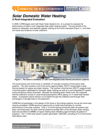
Performance in Warmer ClimatesAs the solar collectors are so closely tied to ambient temperatures, it’s logical that performanceduring warmer weather is dramatically better than performance in colder weather (certainly theamount of sunlight contributes to this as well).This effect is demonstrated by examining the two equinox months. In September 2007, forexample, average daytime temperatures were 69 F, and the solar thermal systems provided75% of the water heating load. In March of 2007, average daytime temperatures were 39 F,and the solar systems provided only 19% of the water heating load. Other weather factors(especially snow) certainly came into play, but all the data show that effect of ambienttemperature on system performance is consistently pronounced. CARB believes that thisunglazed, roof-integrated solar system may provide much higher, more consistent, year-roundbenefits in warmer climates. CARB has not had the opportunity to evaluate any systems inwarmer climates.Operation and MaintenanceWith indirect, glycol-based solar water heating systems, high-temperature protection andensuring proper maintenance are consistent challenges. Propylene glycol breaks down at hightemperatures, and the antifreeze needs to be checked periodically and replaced whennecessary. As discussed above, these roof-integrated systems, with much lower operatingtemperatures, do not require high-temperature protection and glycol will likely last much longerthan in higher-temperature systems. Because of this, maintenance costs, durability, andreliability of these roof-integrated systems may be greatly improved when compared to glazedcollector systems. It is impossible to predict without investigating performance over muchlonger periods of time.Integration of Solar Space HeatingCARB does not generally advocate active solar space heating. The primary challenge with thetechnology is the obvious one: solar energy is least when space heating loads are greatest. Inaddition to this, however, CARB has consistently encountered challenges with the integration ofsolar and auxiliary heating systems.To reach zero energy goals, addressing space heating loads is critical, especially in coldclimates. CARB currently recommends that if solar thermal space heating is used, heat shouldbe delivered to the space through a small, simple system separate from the auxiliary distributionsystem. This may present a controls challenge, but CARB feels that this will be more easilysolved than challenges of integrating the two heat sources with one delivery system.Piping Heat LossIn several recent projects where CARB has monitored performance of solar thermal systems,CARB has expanded monitoring to include the heat loss from piping between the collectors andstorage. In this system, as with others, CARB found that a large amount of energy was lostfrom pipes running between the solar tank (in the basement) and the collector manifolds (in theattic). The pipe runs are rather long (approximately 50-70 feet each way). CARB was informedby the installers that each PEX pipe was insulated with ½” closed-cell foam. In addition, allpipes were run together in an insulated flexible duct (typically used for forced-air distribution).Over the 12-month period, 21.3 MMBtu were collected from the two collector areas on the roof(measured using the temperature differentials at the attic manifolds). Only 8.2 MMBtu, or 38%,Consor tium for A dvance d Re sidential BuildingsSteven Winter Associate s, Inc.www.ca rb -swa .co m50 Wa sh in gt o n St . 6t h F l, No rwa lk , CT 068 54307 7th A ve. Ste. 1701, New York, NY 100011112 16t h St ., N W St e . 240, Wa sh in gt on , D C 20036tel 203-857-0200 fax 203-857-0200tel 212-564-5800 fax 212-741-8673tel 202-628-6100 fax 202-393-5043
were transferred to the solar tanks. The balance was lost through convection and conductionfrom fluid in the piping.When heated glycol reached temperatures of 100 F or more (as measured in the atticmanifolds), the fluid was between 5 F and 10 F cooler when it reached the solar tanks in thebasement. In a low-temperature system, this results in a significant overall energy loss. Thisproblem is not at all specific to this system, however, though it is rather pronounced because ofthe long piping runs and low operating temperatures. CARB now recommends at least R-5ft2hr F/Btu pipe insulation (typically Armaflex or equivalent closed-cell foam with thicknesses ofat least 1-1/4”).Pipe Heat LossesMonthly Energy [kBtu]4,0003,500Pipe Heat Loss3,000Energy Delivered to e 6. Chart showing total solar energy collected divided between useful energy delivered tosolar tanks and heat lost in piping between the attic manifolds and the solar tanks.For more information or comments, contact Robb Aldrich at raldrich@swinter.com.Limits of Liability and Disclaimer of Warranty:Steven Winter Associates, Inc. makes no representations about the suitability of this document for allsituations. The accuracy and completeness of the information provided by the author and the opinionsstated herein are not guaranteed or warranted to produce any particular results and the advice andstrategies contained herein may not be suitable for all applications. This document is provided “as is”'without express or implied warranty. Steven Winter Associates, Inc. shall not be liable in any event forincidental or consequential damages in connection with, or arising out of, the furnishing, performance,or use of this documentation. The information presented in this article is for use with care byprofessionals.Consor tium for A dvance d Re sidential BuildingsSteven Winter Associate s, Inc.www.ca rb -swa .co m50 Wa sh in gt o n St . 6t h F l, No rwa lk , CT 068 54307 7th A ve. Ste. 1701, New York, NY 100011112 16t h St ., N W St e . 240, Wa sh in gt on , D C 20036tel 203-857-0200 fax 203-857-0200tel 212-564-5800 fax 212-741-8673tel 202-628-6100 fax 202-393-5043
The smaller solar thermal system provides heat for domestic water heating only; the large system can provide heat to domestic water or to the radiant floors. Home occupants use manual valves to switch between the two uses of the larger system. On a domestic hot water draw, cold well water flows into the bottom of the smaller solar storage tank.