Transcription
Intelligent controller series for solar water heating control systemContentⅠGeneral information 1ⅡProduct description 2ⅢSystem description 3ⅣFault message 5ⅤPacking list 5
Intelligent controller series for solar water heating control systemⅠ General information1 About this manualThis manual book describes the installation, functions and operation rules of our intelligentcontroller series for solar water heating control system. When install with other applications onthis system, such as solar collector, pump station, and storage, please follow the instruction ofcorrelative suppliers. The installation, electrical connection, adjustment and maintenance shouldbe carried out by a qualified specialist.2 Safety rules- The controller can’t be installed in the room where easily inflammable and explosive mixtures (e.g.gas or oil) are present or may occur.- The controller can’t be installed in the location which exceeds its allowable environment condition.- All operations which require opening the controller are only to be taken without the powersupply. And the operation should be carried out by a qualified specialist.- Before connecting the electrical wire, make sure that the power supply matches the requiredparameter. All devices connected to the controller must match the technical parameter of it.- Once the controller is damaged or failure to work, please take it out of system and inform the supplier.3 Liability waivers- Improper installation or operation can cause damages to material and persons. The manufacturercannot monitor the compliance with these instructions or the circumstances and methods usedfor installation, operation, utilization and maintenance of this device. Damage by mishandling orimproper installation on costumer site is immediately leading to warranty exclusion.- As faults can never be excluded, we don’t offer a guarantee for the completeness of the drawingsand texts of this manual, they only represent some examples. They can only be used on own risk.No liability is assumed for incorrect, incomplete or false information and the resulting damages.- The manufacturer preserves the right to put changes to product, technical date or installation andoperation instructions without prior notice.4 About Sensors- Only original equipped PT1000 temperature sensors can be matched the solar collector. It is equippedwith 1.5m silicone wire and suitable for all kinds of weather conditions. They can resist thetemperature up to 280 . There is no need to distinguish the positive and negative charges whenconnect them to the controller.- Only original equipped NTC10K temperature sensors can be matched the storage and pipeline. It isequipped with 1.5m PVC wire. They can resist the temperature up to 105 . There is no need todistinguish the positive and negative charges when connect them to the controller.- All sensor wires can carry low voltage. In order to avoid inductive effects, the wires must not be laidclose to 230 V or 400 V cables (The min. distance should be 100mm).- If external inductive effects exist, e.g. heavy current cables, overhead train cables, transformersubstations, radio and television devices, amateur radio stations or microwave devices, then thewires for the sensors must be adequately shielded.- Sensor wires can be extended to a maximum length of 100m. When it is extended to 50m, use0.75mm 2 wire. When it is extended to 100m, use1.5 mm 2 wire.1
Intelligent controller series for solar water heating control systemⅡ Product description1 Main technical data- Dimension: 120 120 18mm (Display part), 186 140 41mm (Main part)- Input voltage: 220V 240V AC or 100V 120V AC- Power: 3W- Accuracy of temperature measuring: 1 - Range of temperature measuring: PT1000: 0 199 NTC 10K: 0 99 - Input signals: 1 x PT1000 sensor temperature probe 500 , silicon cable 280 ;2 x NTC10K sensor temperature probe 135 , PVC cable 105 - Output signals: 1 x Auxiliary heating output (Max. load current: 12A)2 x Relay output (Max. load current: 3A)- LCD-display- Range of environment temperature: -10 50 - Water protection grade: IP402 Operation regulations- When connect to power, the default mode is system working mode.- Press “SET” button to start the system data set mode. Every choice is corresponding to differentsignal displays. Please see the description of signals in the following instructions.Press “ ” and “-“ buttons to adjust the set value, press “CONFIRM” button to switch oncorrelative function or confirm the current set value.Press “CANCEL” button to cancel correlative function or cancel the current set value, start thesystem working mode.- On the system data set mode, if not press any button within 15 seconds, the system will cancelthe current set value, and start the system working mode.- On the system working mode, press “CONFIRM” button to switch on the auxiliary heating output.Press “CANCEL” button to switch off the auxiliary heating output.- On the system working mode, press “CONFIRM” button for 2 seconds to switch on or switch offthe R1 output handily. Press “CANCEL” button for 2 seconds to switch on or switch off the R2output handily.- On the system working mode, press “DEFAULT” button to recover all the set value to default value.3 Wire connection2
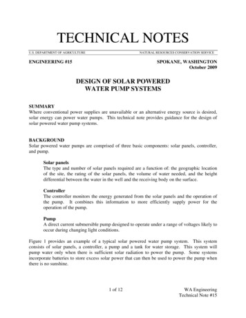
Intelligent controller series for solar water heating control systemⅢ System descriptionSystem 1The standard split pressurized solar water heating system with 1 collector array and 1 storage.Use electrical heater as auxiliary heating device.Relay outputNoteElec. HeatingElec. heaterR1Pump 1R2Pump 2Sensor inputSignalFunctionSystem choiceFactory settingValue arrange11-2Time displayThree time periods onauxiliary heatingThree time periods on hotwater output circulationNoteT1Temp. of CollectorT2Temp. of Storage baseT3Temp. of Storage topDescriptionSystem 1Display the current :00-08:0010:00-10:0000:00-23:5019:00-21:00Adjust the auto. working time periods ofauxiliary heatingAdjust the auto. working time periods of hotwater output circulationAdjust the referenced temp. of auxiliaryStorage keeping temp.60 45-75 Switch-on temp. difference8 5-20 Adjust the desired switch-on temp. differenceSwitch-off temp. difference4 2-12 Adjust the desired switch-off temp. differenceOverheating protection ofstorageheatingWhen the storage reaches the desired80 50-95 overheating protection temp., temp. differencecirculation will be switched off.When the collector temp. is lower than theSystem frost protection3 2-8 desired frost protection temp., this functionwill be activated.This function will be activated when a holidayHoliday functionis planed or when there is no need to use hotwater for a long time.System overheatingprotectionAnti-bacteria protectionWhen the collector is overheating, the130 system stops working, which to avoid theaccessories to be destroyed.To avoid the bacteria occur, the system takesthe bacteria-killing process periodically.3
Intelligent controller series for solar water heating control systemSystem 2The standard split pressurized solar water heating system with 1 collector array and 1 storage.Use gas boiler as auxiliary heating device.Relay outputNoteR1Pump 1R2Pump 2Elec. heatingGas boilerSensor inputSignalFunctionSystem choiceFactory settingValue arrange11-2Time displayThree time periods onauxiliary heatingThree time periods on hotwater output circulationNoteT1Temp. of CollectorT2Temp. of Storage baseT3Temp. of Storage topDescriptionSystem 1Display the current :00-08:0010:00-10:0000:00-23:5019:00-21:00Adjust the auto. working time periods ofauxiliary heatingAdjust the auto. working time periods of hotwater output circulationAdjust the referenced temp. of auxiliaryStorage keeping temp.60 45-75 Switch-on temp. difference8 5-20 Adjust the desired switch-on temp. differenceSwitch-off temp. difference4 2-12 Adjust the desired switch-off temp. differenceOverheating protection ofstorageheatingWhen the storage reaches the desired80 50-95 overheating protection temp., temp. differencecirculation will be switched off.When the collector temp. is lower than theSystem frost protection3 2-8 desired frost protection temp., this functionwill be activated.This function will be activated when a holidayHoliday functionis planed or when there is no need to use hotwater for a long time.System overheatingprotectionAnti-bacteria protectionWhen the collector is overheating, the130 system stops working, which to avoid theaccessories to be destroyed.To avoid the bacteria occur, the system takesthe bacteria-killing process periodically.4
Intelligent controller series for solar water heating control systemⅣ Fault messageNote 1:If there are faults on the controller, please do not repair it by yourself. It should be taken by thequalified specialist.If there is a problem with the controller or temperature sensor, the fault signals will be displayed onthe screen as the following:Fault signal FF FE PossiblecauseThe inside of sensor or the connectionwire between sensor and controller isopen circuit.The inside of sensor or the connectionwire between sensor and controller isshort circuit.SolutionCheck the connection or resistance value of the sensor, replace it on necessary.Note 2:Use Ohmmeter to check the resistance value of sensors. According to the comparative with thestandard value, the fault sensor can be checked out. When check the resistance value, the sensorshould be cut off from the system. Small error can be allowed when compare the test value with thestandard value.PT1000 Resistance value: 11941232127013091347138514221460NTC 10K B 3950 Resistance value: 3013588248617591270933697529407Ⅴ Packing listNo.ItemSpecificationQuantity1Main part170 130 42mm1 pc2Display part120 120 18mm1 pc3Power line4PT1000 sensor1.5m1 pc5NTC sensor1.5m2 pcs6Fixed screw1 bag7Manual1 pc1 pc5
Intelligent controller series for solar water heating control system 3 Ⅲ System description System 1 The standard split pressurized solar water heating system with 1 collector array and 1 storage. Use electrical heater as auxiliary heating device. Relay output Note Elec. Heating Elec. heater R1 Pump 1 R2 Pump 2 Sensor input Note