Transcription
Laboratory ManualRefrigeration & AirConditioning LabBachelor of TechnologyVIth SemesterMechanical Engineering1
B.TechSem- 6 MESub Code- 7P.353Refrigeration & Air Conditioning Lab.L0T0P2C1List of Experiments:1. Study on refrigeration Test Rig.2. To study function and working of different parts of an Air Conditioning equipment.3.Study on Heat Exchanger.4.Study on compression system.5.Visit report on Ice Plant.2
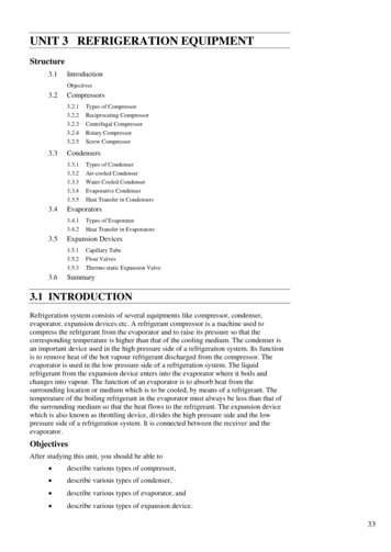
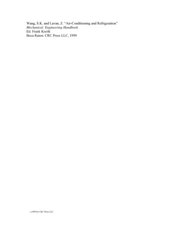
EXPERIMENT No: 1AIM:Study on refrigeration Test Rig.THEORY:Theory of Vapour compression refrigeration cycle is explained.Figure 1: Vapor Compression Test RigA vapour compression refrigeration system is an improved type of air refrigeration system in which asuitable working substance, termed as refrigerant is used. It condenses and evaporates at temperaturesand pressures close to the atmospheric conditions.The refrigerant used does not leave the system but is circulated throughout the system alternatelycondensing and evaporating. The vapour compression refrigeration system is now days used for allpurpose refrigeration. It is used for all industrial purpose from a small domestic refrigerator to a big airconditioning plant.The vapour compression refrigeration cycle is based on the following factor:1. Refrigerant flow rate.2. Type of refrigerant used.3. Kind of application viz air-conditioning, refrigeration, dehumidification etc.4. The operation design parameters.5. The system equipments/ components proposed to be used in the system.3
The vapour compression refrigeration cycle is based on a circulating fluid media, viz, a refrigerant havingspecial properties of vaporizing at temperatures lower than the ambient and condensing back to theliquid form, at slightly higher than ambient conditions by controlling the saturation temperature andpressure. Thus, when the refrigerant evaporates or boils at temperatures lower than ambient, it extractsor removes heat from the load and lower the temperature consequently providing cooling.The super-heated vapour pressure is increased to a level by the compressor to reach a saturationpressure so that heat added to vapour is dissipated/ rejected into the atmosphere, using operationalambient conditions, with cooling medias the liquid from and recycled again to form the refrigerationcycle.The components used are:1. Evaporator2. Compressor3. Condenser and receiver4. Throttling deviceThe refrigeration cycle can be explained schematically in the two diagrams i.e. Pressure enthalpydiagram Temperature entropy diagram.The working of vapour compression refrigeration cycle and function of each above component is givenbelow.Figure 2: Components of vapour refrigeration system4
Evaporator:The liquid refrigerant from the condenser at high pressure is fed through a throttling device to anevaporator at a low pressure. On absorbing the heat to be extracted from Media to be cooled, the liquidrefrigerant boils actively in the evaporator and changes state. The refrigerant gains latent heat tovaporize at saturation temperature/ pressure and further absorbs sensible heat from media to becooled and gets fully vaporized and super heated.Compressor:The low temperature, pressure, superheated vapour from the evaporator is conveyed through suctionline and compressed by the compressor to a high pressure, without any change of gaseous state and thesame is discharge into condenser. During this process heat is added to the refrigerant and known asheat of compression ratio to raise the pressure of refrigerant to such a level that the saturationtemperature of the discharge refrigerant is higher than the temperature of the available coolingmedium, to enable the super heated refrigerant to condense at normal ambient condition. Differenttypes of compressors are reciprocating, rotary and centrifugal and are used for different applications.Condenser:The heat added in the evaporator and compressor to the refrigerant is rejected in condenser at hightemperature/ high pressure. This super heated refrigerant vapour enters the condenser to dissipate itsheat in three stages. First on entry the refrigerant loses its super heat, it then loses its latent heat atwhich the refrigerant is liquefied at saturation temperature pressure. This liquid loses its sensible heat,further and the refrigerant leaves the condenser as a sub cooled liquid. The heat transfer fromrefrigerant to cooling medium (air or water) takes place in the condenser. The sub-cooled liquid fromcondenser is collected in a receiver (wherever provided) and is then fed through the throttling device byliquid line to the evaporator.There are several methods of dissipating the rejected heat into the atmosphere by condenser. These arewater-cooled, air cooled or evaporative cooled condensers.In the water-cooled condenser there are several types viz. Shell and tube, shell and coil, tube in tube etc.In Evaporative cooled condenser, both air and water are used. Air-cooled condensers are prime surfacetype, finned type or plate type. The selecting of the type depends upon the application and availabilityof soft water.Throttling device:The high-pressure liquid from the condenser is fed to evaporator through device, which should bedesigned to pass maximum possible liquid refrigerant to obtain a good refrigeration effect. The liquidline should be properly sized to have minimum pressure drop.The throttling device is a pressure-reducing device and a regulator for controlling the refrigerant flow. Italso reduces the pressure from the discharge pressure to the evaporator pressure without any change ofstate of the pressure refrigerant.5
The types of throttling devices are:1.Capillary tubes 2. Hand expansion valves 3. Thermostatic expansion valveThe most commonly used throttling device is the capillary tube for application upto approx. 10refrigeration tons. The capillary is a copper tube having a small dia-orifice and is selected, based on thesystem design, the refrigerant flow rate, the operating parameters (such as suction and dischargepressures), type of refrigerant, capable of compensating any variations/ fluctuations in load by allowingonly liquid refrigerant to flow to the evaporator.CONCLUSION:Various components of the vapour compression system have been studied.6
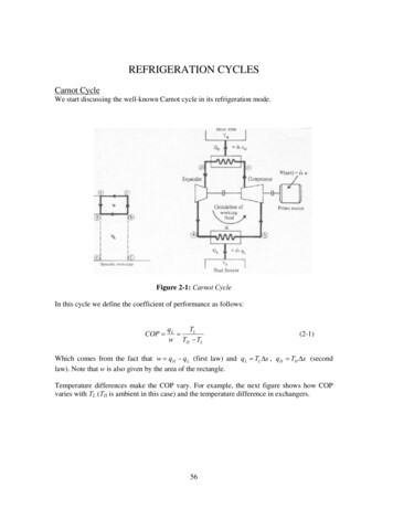
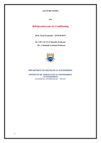
EXPERIMENT No:2AIM:To study function and working of different parts of an Air Conditioning equipment.APPARATUS:A model of window room air conditioner.THEORY:A room air conditioner is a compact air conditioner unit which can be placed in a particular room for itsair conditioning. The room may be an office, a residential room such as bed room, living room etc. Thewindow type units are air cooled and are mounted in a window or wall of room to be air conditioned.They do not need any ductwork. It has a complete refrigeration plane, i. e. compressor, condenser,refrigerant, valves and evaporator coilsThe units are also provided with thermostat control and filtering equipment.A window room air conditioner is shown in Fig.A window type air conditioner consists of following sub-assembles:Sub assemblyParts1. System assemblya. Evaporatorb. Capillaryc. Condenserd. Strainere. Compressor2. Motor, fan and blower assemblya. Fanb. Blower motorc. Motor mounting brackets3. Cabinet and grill assemblya. Cabinetb. Grill4. Switch board panela.b.c.d.Selector switchRelayThermostatFan motor capacitorWORKING:The cool and low pressure vapour refrigerant is drawn from the evaporator to the compressor and it iscompressed to high pressure and temperature. Generally, in this refrigerant is Freon gas i.e. R-12 or R22 and a hermetic compressor is used. The high pressure and temperature gas runs through a set ofcoils so it can dissipate its heat and it condenses into liquid. The liquid is passed through the capillaryand then flows into the evaporator. As refrigerant comes out of capillary, its temperature and pressurefalls. This low temperature and pressure gas runs through a set of coils that allow the gas to absorb heatand cool down the air inside the building. The compressor draws this low pressure vapour and cycle is7
repeated. Most air conditioner also functions as dehumidifiers. They take excess water or moisture fromthe air and exit to atmosphere through the pipe.Some factors should be kept in mind while selecting an air conditioner for a room:1.2.3.4.Size of the roomWall construction, whether light or heavyHeat gain through ceiling and proportion of outside wall area which is covered with glassWhether the room is to be used in the day time or at night only. The exposure to the sun of thewalls of the room to be air conditioned and Room Ceiling height5. Number of persons likely to use the room6. Miscellaneous heat loads such as wattage of lamps, radio, television, computer, etc.Fig. 1Fig. 2CONCLUSION:The model of Air conditioner was demonstrated and its working was studied.8
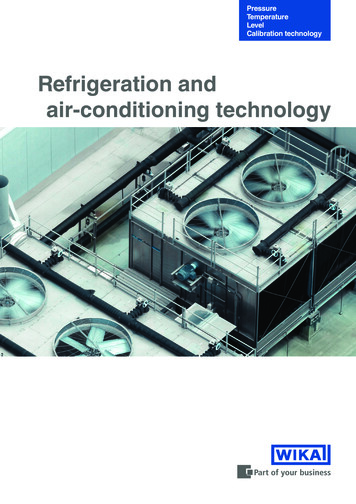
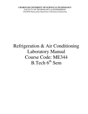
EXPERIMENT No: 3AIM:Study on heat exchangerTHEORY:A heat exchanger is a device used to transfer heat between a solid object and a fluid, or between two ormore fluids. The fluids may be separated by a solid wall to prevent mixing or they may be in directcontact.They are widely used in space heating, refrigeration, air conditioning, power stations, chemical plants,petrochemical plants, petroleum refineries, natural-gas processing, and sewage treatment.The classic example of a heat exchanger is found in an internal combustion engine in which a circulatingfluid known as engine coolant flows through radiator coils and air flows past the coils, which cools thecoolant and heats the incoming air. Another example is the heat sink, which is a passive heat exchangerthat transfers the heat generated by an electronic or a mechanical device to a fluid medium, often air ora liquid coolant.Types of Heat Exchanger:1. Double pipe heat exchanger:Double pipe heat exchangers are the simplest exchangers used in industries. On one hand, these heatexchangers are cheap for both design and maintenance, making them a good choice for small industries.On the other hand, their low efficiency coupled with the high space occupied in large scales, has ledmodern industries to use more efficient heat exchangers like shell and tube or plate. However, sincedouble pipe heat exchangers are simple, they are used to teach heat exchanger design basics tostudents as the fundamental rules for all heat exchangers are the same.9
2. Shell and tube heat exchanger:Shell and tube heat exchangers consist of series of tubes. One set of these tubes contains the fluid thatmust be either heated or cooled. The second fluid runs over the tubes that are being heated or cooledso that it can either provide the heat or absorb the heat required. A set of tubes is called the tubebundle and can be made up of several types of tubes: plain, longitudinally finned, etc. Shell and tubeheat exchangers are typically used for high-pressure applications (with pressures greater than 30 barand temperatures greater than 260 C).This is because the shell and tube heat exchangers are robustdue to their shape.3. Plate heat exchanger:Another type of heat exchanger is the plate heat exchanger. These exchangers are composed of manythin, slightly separated plates that have very large surface areas and small fluid flow passages for heattransfer. Advances in gasket and brazing technology have made the plate-type heat exchangerincreasingly practical.When compared to shell and tube exchangers, the stacked-plate arrangement typically has lowervolume and cost. Another difference between the two is that plate exchangers typically serve low tomedium pressure fluids, compared to medium and high pressures of shell and tube. A third andimportant difference is that plate exchangers employ more countercurrent flow rather than crosscurrent flow, which allows lower approach temperature differences, high temperature changes, andincreased efficiencies.10
4. Helical-coil heat exchanger:The main advantage of the HCHE, like that for the SHE, is its highly efficient use of space, especiallywhen it’s limited and not enough straight pipe can be laid. Under conditions of low flow rates (orlaminar flow), such that the typical shell-and-tube exchangers have low heat-transfer coefficients andbecoming uneconomical. When there is low pressure in one of the fluids, usually from accumulatedpressure drops in other process equipment.When one of the fluids has components in multiple phases(solids, liquids, and gases), which tends to create mechanical problems during operations, such asplugging of small-diameter tubes. Cleaning of helical coils for these multiple-phase fluids can prove to bemore difficult than its shell and tube counterpart; however the helical coil unit would require cleaningless often.These have been used in the nuclear industry as a method for exchanging heat in a sodiumsystem for large liquid metal fast breeder reactors since the early 1970s.5. Spiral Heat Exchanger:A modification to the perpendicular flow of the typical HCHE involves the replacement of shell withanother coiled tube, allowing the two fluids to flow parallel to one another, and which requires the useof different design calculations. These are the Spiral Heat Exchangers (SHE), which may refer to a helical(coiled) tube configuration, more generally, the term refers to a pair of flat surfaces that are coiled toform the two channels in a counter-flow arrangement. Each of the two channels has one long curvedpath. The main advantage of the SHE is its highly efficient use of space. This attribute is often leveragedand partially reallocated to gain other improvements in performance, according to well known tradeoffsin heat exchanger design. (A notable tradeoff is capital cost vs operating cost.) A compact SHE may beused to have a smaller footprint and thus lower all-around capital costs, or an oversized SHE may beused to have less pressure drop, less pumping energy, higher thermal efficiency, and lower energy costs.CONCLUSION:Different types of heat exchangers were studied.11
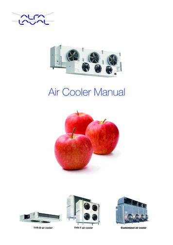
EXPERIMENT No: 4AIM:Study on compression system.APPARATUS USED:Model of Reciprocating, Centrifugal and Rotary compressorTHEORY:1. Reciprocating compressor:The compressors in which the vapour refrigerant is compressed by reciprocating motion of the pistonare called reciprocating compressors. These compressors are used for refrigerant which havecomparatively low volume per Kg and a large differential press. Such as NH 3(R-717), R-12, R-22. Thereciprocating compressors are available in sizes as small as ½ KW which are used in small domesticrefrigeration and up to about 150 KW for large capacity.The single acting compressors usually have their cylinder arranged vertically radially or in ‘V’ or ‘W’form. The double acting compressors usually have their cylinder arranged horizontal.When the piston moves downwards, the refrigerant left in the clearance space expands. Thus, thevolume of the cylinder increase and the pressure inside the cylinder decreases. When the pressurebecome slightly less then the valve gets opened and the vapour refrigerant flows into the cylinder. Thisflow continuous until the piston reaches the bottom of the stroke. At bottom of the stroke, the suctionvalve closes because of spring action. Now, when the piston moves upwards, the volume of the pistonmoves upwards, the volume of the cylinder decreases and the pressure inside the cylinder increases.When the pressure inside the cylinder becomes greater than that on the top of the discharge valve, thedischarge valve gets opened & the vapour refrigerant is discharged into the condenser and the cycle isrepeated.12
2. Rotary compressor:In rotary compressor, the vapour refrigerant from the evaporator is compressed due to movement ofblades. The rotary compressors are positive displacement type compressor. Since, the clearance inrotary compressors is negligible; therefore, they have high ηvol. These may be used for refrigerants likeR-12, R-22, and R-144 & NH3.The two types of rotary compressors are: a. Single stationary blade typeb. Rotating blade typeSingle stationary blade type consists of a stationary cylinder, a roller and a shaft. The shaft has aneccentric on which the roller is mounted. A blade is set into the slot of a cylinder in such a manner thatit always maintains contacts with a sloter by means of a spring. The blade moves in and out of the slot tofollow the rotor when it rotates. Since the blade separates the suction and discharge parts, therefore itis often called a sealing blade. When the shaft rotates, the roller also rotates the roller rotates so that italways touches the cylinder wall.Rotating Blade type consists of a cylinder and a slotted rotor containing a number of blades. The centreof the rotor is eccentric with the centre of the cylinder. The blades are forced against the cylinder wallby the centrifugal action during the rotation of the motor. The low pressure and temperature vapourrefrigerant from the evaporator is drawn through the suction port. As the rotor turns, the suctionvapour refrigerant entrapped between the two adjacent blades is compressed. The compressedrefrigerant at high pressure and temp is discharged through the discharge port to the condenser.13
3. Centrifugal CompressorThe centrifugal compressor increases the pressure of low pressure vapour refrigerant to a high pressureby centrifugal force. The centrifugal compressor is generally used for refrigerants that require largedisplacement and low condensing pressure, such as R-12. However, the refrigerant R-12 is alsoemployed for large capacity applications and low-temperature applications.A single stage centrifugal compressor, in its simplest form, consists of an impeller to which a number ofcurved vanes are fitted symmetrically. The impeller rotates in an air volute casing with inlet and outletpoints. The impeller draws in low pressure vapour refrigerant from the evaporator. When the impellerrotates, it pushes the vapour refrigerant from the centre of the impeller to its periphery by centrifugalforce. The high speed of the impeller leaves the vapour refrigerant at a high velocity at the vane tips ofthe impeller. The kinetic energy thus attained at the impeller outlet is converted into pressure energywhen the high velocity vapour refrigerant passes over the diffuser. The diffuser is normally a vane lesstype as it permits more efficient part load operation which is quite and it further converts the kineticenergy into pressure energy before it leaves the refrigerant to the evaporator.CONCLUSION:Various compression systems were studied.14
A room air conditioner is a compact air conditioner unit which ca n be placed in a particular room for its air conditioning. The room may be an office, a residential room such as bed room, living room etc. The window type units are air cooled and are mounted in a window or wall of room to be air conditioned. They do not need any ductwork.