Transcription
FAARFIELD 1.4Implementing NewCompaction ProvisionsPresented to:XI ALACPA Seminar on Airport Pavements andIX FAA Workshop, Santiago de ChileBy: David R. Brill. P.E., Ph.D.Date: 3 September, 2014Federal AviationAdministration
Compaction Requirements FAA design procedures (AC 150/5320-6E)assume that minimum compactionrequirements are met. Subgrade compaction requirements areexpressed as a minimum percentage of themaximum dry density by:– ASTM D 1557 (Modified Proctor) for pavementsserving airplanes 27,216 kg (60,000 lbs.) GW.– ASTM D 698 (Standard Proctor) for light loadpavements (serving airplanes 27, 216 kg).03 September 2014XI ALACPA Seminar / IX FAAWorkshop, Santiago de ChileFederal AviationAdministration2
Why Compaction Requirements? Minimum density requirements for soils areintended to prevent additional densificationunder in-service aircraft traffic. Curves of minimum required density versusCBR (Compaction Index, CI) were developedfrom observed field data in the 1950’s.* Established separate relationships forcohesive and non-cohesive soil types.*See Ahlvin, Compaction Requirements for Soil Components ofFlexible Airfield Pavements, US Army WES, TR 3-529, 1959.03 September 2014XI ALACPA Seminar / IX FAAWorkshop, Santiago de ChileFederal AviationAdministration3
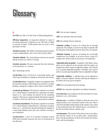
Compaction Index (CI) CI is defined as:“the CBR required at a givendepth for a particular wheelconfiguration, assembly loadand tire pressure.” CI is computed for depthmeasured from surface. Proposed criteria developedby Richard Ahlvin werenever implemented by theFAA and are not consistentwith the current standards inAC 150/5320-6E.03 September 2014Suggested criteria for percentmodified maximum density as afunction of CI, based on Ahlvin (1989)% Maximum DensityXI ALACPA Seminar / IX FAAWorkshop, Santiago de Chile a be c (CI )dFederal AviationAdministration4
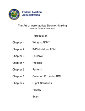
Current Compaction RequirementsAC 150/5320-6E, Table 3-4 Compaction requirementsare given in a table,independent of FAARFIELDthickness design. Control points arereferenced to the top ofsubgrade, regardless ofpavement thickness orsubgrade CBR. This istheoretically incorrect. Extrapolation to new largeaircraft types (B777 andA380) is not reliable.03 September 2014XI ALACPA Seminar / IX FAAWorkshop, Santiago de ChileFederal AviationAdministration5
FAARFIELD 1.4Automated Compaction Requirements Implements rational compaction criteriabased on the CI. Fully integrated with FAARFIELD 1.4thickness design.– Compaction criteria are computed at design timebased on the design traffic mix.– Output in tabular form as part of the design report. Displays compaction control points withrespect to both pavement surface and top ofsubgrade.03 September 2014XI ALACPA Seminar / IX FAAWorkshop, Santiago de ChileFederal AviationAdministration6
7 Steps to Compute the CompactionRequirement Automatically1.2.3.For 6000 annual departures of a given aircraft, use FAARFIELD tocompute vertical stress (layered elastic) and the pass-to-coverageratio (P/C) at each depth of interest.At each depth z of interest, compute coverages C 6000 / (P/C).At each depth z of interest, compute the stress ratiou 12 r uu 1 and r is the radius of one wheel.whereS 3:2 ( z ) z u 14.5.6.7.The equivalent stress for computing CI is the product of thevertical stress in step 1 and the ratio in step 3.1.7782 0.2397 log(C )Compute β from log(β ) 1 0.5031 log(C ) (Gonzalez, 2012).σ z(n 2 ) πCompute CI .βDetermine the compaction requirement from the appropriate curve.03 September 2014XI ALACPA Seminar / IX FAAWorkshop, Santiago de ChileFederal AviationAdministration7
Example – Flexible DesignConsider theprevious flexiblepavement designexample: 10-aircraft mixincluding A380,B777-300 ER,B787, etc. Stabilizedpavement designconsistent withFAA standards.03 September 2014XI ALACPA Seminar / IX FAAWorkshop, Santiago de ChileFederal AviationAdministration8
Compute Compaction Hit Alt-O to bringup the Optionsscreen. Check the boxlabeled“ComputeCompactionRequirements” Click OK03 September 2014XI ALACPA Seminar / IX FAAWorkshop, Santiago de ChileFederal AviationAdministration9
Compute CompactionClick the “Life”Button.03 September 2014XI ALACPA Seminar / IX FAAWorkshop, Santiago de ChileFederal AviationAdministration10
Compute CompactionClick “Back” toreturn to the mainscreen.03 September 2014XI ALACPA Seminar / IX FAAWorkshop, Santiago de ChileFederal AviationAdministration11
Compute CompactionSelect “Notes” todisplay the designreport.03 September 2014XI ALACPA Seminar / IX FAAWorkshop, Santiago de ChileFederal AviationAdministration12
Compute CompactionScroll down untilthe heading“SubgradeCompactionRequirements”is displayed.Two tables displaythe compactionrequirements fornon-cohesive andcohesive soils,respectively.Compaction depthshere given in mm.03 September 2014XI ALACPA Seminar / IX FAAWorkshop, Santiago de ChileFederal AviationAdministration13
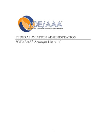
Compaction TablesPercent of Max.Dry DensityDepth fromSurfaceDepth from Topof SubgradeCritical Airplanefor CompactionModified Proctor (Heavy Load)03 September 2014XI ALACPA Seminar / IX FAAWorkshop, Santiago de ChileFederal AviationAdministration14
Compaction ExampleFor the flexible design example above, assume: Top of subgrade will be approximately 250 mm (10 inches) below theexisting ground surface. In-place soils have PI 20 (cohesive). Investigation shows the following in-place soil densities in this area:Depth BelowExisting GradeDepth BelowDepth BelowTop of Subgrade Finish GradeIn-Place Density0.3 m (1 ft.)0.05 m0.85 m70%0.6 m (2 ft.)0.350 m1.15 m84%0.9 m (3 ft.)0.650 m1.45 m86%1.2 m (4 ft.)0.950 m1.75 m90%1.5 m (5 ft.)1.250 m2.05 m93%03 September 2014XI ALACPA Seminar / IX FAAWorkshop, Santiago de ChileFederal AviationAdministration15
Compaction Example Use the FAARFIELD 1.4generated table forcohesive soils. In-place density issatisfactory at a depthof 1.75 m below finishgrade (.95 m below topof subgrade). Compact the top 16 cmto 95% and 16-95 cm to90% max. density.03 September 2014XI ALACPA Seminar / IX FAAWorkshop, Santiago de ChileFederal AviationAdministration16
Richard G. Ahlvin 1919-2014Dick Ahlvin, who retiredfrom the US ArmyWaterways ExperimentStation in 1983, passedaway on August 26, 2014.He will be rememberedfor his deep knowledgeand many contributionsto the field of airportpavement engineering.03 September 2014XI ALACPA Seminar / IX FAAWorkshop, Santiago de ChileFederal AviationAdministration17
Thank You! ¡Muchas ill@faa.govAcknowledgments:FAA Airport Technology R&D Branch:Dr. Michel Hovan, Branch Manager;Jeff Gagnon, Airport Pavement Section Manager;Dr. Navneet Garg; Al Larkin; Dr. Charles Ishee; Murphy Flynn; Ryan Rutter; Quinn Jia, Wilfredo VillafaneFAA Airport Engineering Division:Doug Johnson; Greg ClineSRA International:Jerry Connelly; Dr. Izydor Kawa; Dr. Qiang Wang; Dr. Yuanguo Chen; Dr. Kairat Tuleubekov, Jeff SteinGemini:Dr. Hao YinConsultants:Dr. Edward Guo; Dr. Maria Lopez; Roy McQueen; Dr. Shelley Stoffels03 September 2014XI ALACPA Seminar / IX FAAWorkshop, Santiago de ChileFederal AviationAdministration18
– ASTM D 1557 (Modified Proctor) for pavements serving airplanes 27,216 kg (60,000 lbs.) GW. – ASTM D 698 (Standard Proctor) for light load pavements (serving airplanes 27, 216 kg). 03 September 2014 XI ALACPA Seminar / IX FAA Workshop, Santiago de Chile 2