Transcription
GlidePath Operator’s HandBookw w w.tti.com.auManufacturer of “The Safest Tanks in Motion”
GlidePath Product HandBookContentsSafety4General Safety Instructions4General Information5Specifications5Description6Machine Limitations8Driving Stability8Spray Boom Calibration8Calibration Procedure9GlidePath Operating Instructions11Before First Use11Filling the GlidePath Tank12Operating Instructions13Clean-up and Decontamination19Cleaning Procedure19Cleaning Procedure using Flush Tank20Maintenance21Periodic Checks21Maintenance Schedule21Maintenance Tasks24Trouble Shooting25Pump25Risk Assessment26Warranty27Warranty Policy27What this Warranty Does Not Cover?27How to Obtain Service Under this Warranty?27Warranty Limitations27w w w.tti.com. au21800 816 277
GlidePath Product HandBookDisclaimerAll information, illustrations, and specifications contained in this manual are based on the latest productinformation available at the time of this publication’s printing. TransTank International (TTi) reserves the rightto alter and substitute specifications and methods at any time, in line with our commitment to continuousimprovement.No patent liability is assumed with respect to the use of information contained within this manual. Whileevery precaution has been taken in the preparation of this manual, TTi assumes no responsibility for errors oromissions.Thank you for purchasing a TTi GlidePath Spray Trailer with Folding Boom(GlidePath), which will provide many years of reliable service when operatedand maintained in accordance with this manual.TTi manufacture two GlidePath capacities, 1,000 and 1,200 litre tanks. The GlidePath is supplied completewith a Bertolini pump powered by a genuine Honda GX200 engine, all mounted on a robust, heavy dutygalvanised steel trailer. Both braked (road registerable) and unbraked versions of the trailer are available.Standard inclusions are a 20 litre handwash/flush tank with tap and a 3-way pressure regulator and gaugefor accurate spraying. The GlidePath is available with a range of options, including spray booms, 30m or50m hose reels, a foam marker kit, GPS system, electric start for the pump engine and remote electricalcontrol switches.This manual describes the operation, driving stability and maintenance procedures applicable to all units,noting additional requirements to options where necessary.All TTi GlidePath tanks are rotationally moulded from quality polyethylene, purpose designed andmanufactured to high standards. The GlidePath is specifically designed to be towed by your vehicle andused for everything from herbicide to pesticide spraying.The GlidePath unit is supplied complete, tested and ready to hitch to your vehicle or tractor. TTi warrantsthat the GlidePath has been designed and built for its intended purpose as a pesticide/herbicide spray unit.The owner is responsible to ensure that the equipment is operated in accordance with this manual, withAustralian WorkSafe requirements, applicable road rules and local council regulations. TTi is not liable forany loss, injury or death resulting from the failure to observe all safe working regulations as required by law.Included with your GlidePath unit are the following documents: Operator’s Handbook (this manual, which includes the Warranty Registration Card) Honda petrol engine handbook Bertolini pump data sheet (includes link to download pump manual). TTi recommends that you download thismanual. Tank Quality Check Form. This is your verification that the unit has been quality checked, and verifiesthe serial number affixed to the unit.w w w.tti.com. au31800 816 277
GlidePath Product HandBookSafetyThis manual is intended for use by personnel experienced in the use of this and similar equipment. Readand understand this manual before attempting to operate or perform routine maintenance on this equipment.Your safety is of prime priority.A WARNING highlights an essential operating or maintenance procedure,practice, condition or statement, which, if not strictly observed, could resultin injury or death of personnel, or long-term health hazards.A CAUTION highlights an essential operating or maintenance procedure,practice, condition or statement, which, if not observed, could result indamage or destruction of equipment.A NOTE highlights or clarifies an essential systems description, operating ormaintenance procedure, condition or statement.General Safety Instructions1.This unit is designed and manufactured solely for the purpose of carrying and spraying herbicides andpesticides. Under no circumstances should it be used for any other purpose. It must never be used fortransporting fuel.2. Only authorised and trained personnel are to operate this equipment. Operators must have read and fullyunderstood this manual before operating the GlidePath unit.3. Do not operate the GlidePath anywhere near bystanders, livestock, watercourses or any non-targetedvegetation that may be in danger from spray drift contamination.4. Wind direction and speed must be taken into account, as windy conditions may endanger the operator ordamage to adjacent non-target vegetation. Avoid spraying on hot and sunny days or when wind speedexceeds 6.5km/h.5. Do not operate this equipment while under the influence of alcohol or any drugs that could impair yourcapabilities in any way.6. PPE appropriate to the chemicals being used must be worn at all times when operating the GlidePath.As a minimum, the PPE should include coveralls, gloves and boots. A face shield and PVC apron arerecommended depending on the task. It is recommended that the following documents should be readand understood by the operator: Australian Standard for Chemical protective clothing AS3765 Australian Standard for Respiratory protection devices AS17157. Ensure the capacity of the tow vehicle is suitable for the loaded mass of the GlidePath. Refer to thevehicle’s operator manual for safe working loads, correct securing points and relevant safety instructions.Do not exceed the carrying and braking capacity as specified by the vehicle manufacturer. As a guide, onelitre of water weights one kilogram (kg), therefore a full 1,000 litre GlidePath will weigh in excess of 1,200kgwithout options.8. Care should be taken at all times, particularly when operating on rough or steep terrain. Drivers should beaware of fluid surge affecting the vehicle’s centre of gravity.w w w.tti.com. au41800 816 277
GlidePath Product HandBook9. The GlidePath must never be left unattended while being filled with fluids.10. Do not operate the pump when there is no fluid in the tank.11. Do not disconnect any hoses, nozzles or filters while the equipment is operating. Disconnecting anycomponents while under pressure may result in uncontrolled fluid discharge which may be hazardous.12. Ensure any electrical connections are properly configured, to prevent damage such as shorting or reversepolarity.13. At completion of operation, turn the pump off and relieve any residual pressure by squeezing the optionallyfitted spray gun trigger or opening a spray boom valve.14. At completion of the operation, decontaminate the GlidePath tank and spray lines. Drain any residuechemicals and store in a sealed container. Dispose of any unwanted chemicals and tank rinse residue inaccordance with current environmental and workplace health and safety regulations.15. The GlidePath has safety labels affixed to various locations on the unit. These labels should be kept cleanand legible, and replaced if damaged.16. Any unauthorised modifications to this equipment may affect its function and create a serious safety risk.Any unauthorised modifications will void any warranty on the unit.General InformationSpecificationsTankUV stabilised, chemical resistant polyethylene tank complete –1,000 and 1,200litre capacities, fully drainable. A 20L handwash/flush tank with tapTrailerFully welded and galvanised heavy duty steel frame, single axle with 15” Sunraysiawheels with 6-stud pattern and adjustable boom height settings.Standard EquipmentHonda GX200 engine coupled to Bertolini pump delivering 75L/min3-way pressure regulator and gaugeOptionsPinnacle Self-leveling steel booms, with 8m, 10m and 12m spray swath30m hose on hose reel with spray gun50m SuperReel with auto-rewind with spray gunDouble-sided foam marker kit with solenoid controlTeeJet Matrix 430 GPS Guidance SystemRemote control solenoid operated ON-OFF switch unitRemote control solenoid operated 3-way pressure regulator and ON-OFF switchunitElectric start for Honda GX200 engineTank level gaugew w w.tti.com. au51800 816 277
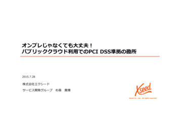
GlidePath Product HandBookDescriptionThe TTi GlidePath Spray Trailer is designed to carry and distribute herbicides or pesticides using an integralpump and various fluid dispensing systems. The GlidePath is available with the following options 8m, 10m or 12m Pinnacle Self-leveling Boom: 30m hose on hose reel with spray gun 50m auto-rewind SuperReel with spray gun Electric start for the Honda engine Double-sided foam marker kit with solenoid control TeeJet Matrix 430 GPS Guidance System Remote control solenoid operated ON-OFF switch unit Remote control solenoid operated 3-way regulator and ON-OFF switch unitThe GlidePath has the following features, refer to Figure 1.Figure 1 – Component Identification – GlidePath with hose reel, boom and foam marker kit optionsPumpThe GlidePath is fitted with a Bertolini 75L/min pump driven directly by a Honda GX200 petrol engine. If theoptional spray boom or spray gun is not in operation when the pump is running, the fluid bypasses back intothe tank.8m, 10m and 12m Pinnacle Self-leveling BoomsThe Pinnacle galvanised boom has steel plate protected non-drip nozzles fitted with TeeJet AIXR Air Inductionspray tips. The boom incorporates a break-away feature to prevent damage if the unit hits an obstacle, andeasily folds for transportation and storage. The boom structure incorporates a self-leveling mechanism totake into account uneven terrain. From the driver’s seat, the operator can start and stop spray operationsusing the optional electrically operated solenoid valve on the 3-way regulator.w w w.tti.com. au61800 816 277
GlidePath Product HandBookFoam Marker KitAn optional Foam Marker Kit is available for the GlidePath and includes a 20L container with a spray nozzlemounted on each end of the boom. With the container filled with a rich soapy water solution, the electricallyactuated solenoid valve operates at factory-set intervals to discharge a short burst of foam onto the ground.This provides a visual indication of the spray swath run, enabling accurate coverage for the next, adjacentpass.Power for the solenoid valve is provided by the tow vehicle’s electrical system via the supplied cable andcontroller.30m Hose Reel and Spray GunThe GlidePath has an optional manually operated hose reel containing 30m of 10mm diameter hose connectedto a trigger actuated PowerJet spray gun with adjustable brass nozzle. The hose is pulled out manually fromthe reel and retracted using the handle on the side. The spray gun is stowed in a holder incorporated in thegalvanised steel frame.The nozzle adjusts from jet through to mist sprays by rotating the nozzle head. When the trigger is squeezed,the fluid is discharged; when the trigger is released, the fluid bypasses back into the tank.50m SuperReel and Spray GunThe electrically operated SuperReel hose reel contains 50m of FrictionFreeTM hose connected to a triggeractuated Turbo spray gun with adjustable nozzle. The hose is pulled out manually from the SuperReel andelectrically retracted using the supplied remote control. An Anderson plug is fitted to the rear of the SuperReel,ready for connection to a 12-volt power supply.The spray gun nozzle adjusts from jet through to mist sprays by adjustment of the lever adjacent to the trigger.When the trigger is squeezed, the fluid is discharged; when the trigger is released, the fluid bypasses backinto the tank.Pressure RegulatorA pressure regulator and pressure gauge are mounted to the trailer’s galvanised steel frame to control linepressure and prevent pump cavitation. The regulator is adjustable depending on the operation requirements– for boom spraying, the regulator is to be set to approximately 3 bar; with spot spraying via the optional hosethe regulator is set to approximately 5 bar.Manually Operated ValvesManually operated 3-way valves are incorporated into the pressure regulator manifold, enabling individualadjustment of boom spray operation and the optional hose reel.Solenoid Operated ValveAn optional electrically operated solenoid valve can be mounted on the pressure regulator manifold and turnsthe entire manifold either ON or OFF via a remote control single switch unit.The pressure regulator manifold can be optionally fully equipped with solenoid operated valve controllers,enabling the 3-way valves to be operated individually, as well as the entire manifold via the remote control4-switch unit.Suction FilterA filter is installed on the suction line below the tank and protected by a guard incorporated into the steelframe. The filter has a removeable filter element for easy cleaning.w w w.tti.com. au71800 816 277
GlidePath Product HandBookPump Engine BatteryWith the optioned electric pump start upgrade, a separate, dedicated 12-volt battery is installed on the trailerbehind the pump unit.TrailerThe trailer frame is an all steel, fully welded construction and hot dip galvanised for corrosion resistance. Theframe has additional welded gussets for added strength and filled-in chequer plate mudguards to protect thetank. The single solid axle is fitted with 6-stud 15-inch Sunraysia wheels and available as unbraked or braked(registerable) with hydraulic brakes.The boom mount incorporates vertical slots, enabling the boom to be easily adjusted in height.TankAll TTi tanks are constructed from UV stabilised, chemical resistant, virgin material polyethylene. The tank isfully drainable and has an internal basket strainer under the filling cap.Tank Level IndicatorAn optional level sight tube is fitted to the side of the tank and provides an accurate level indication of fluidwithin the tank.Flush TankThe 20-litre flush tank is mounted in front of the GlidePath tank. A 3-way control valve draws water from theflush tank through the lines and optional hose reel. The main tank can be then flushed with clean water byremoving the suction line from the sump.Machine LimitationsThe GlidePath units are subject to operating limitations. It is the operator’s responsibility to ensure that thisequipment is being operated safely and within these limitations.Driving StabilityThe GlidePath unit is heavy when filled with fluid. To maintain stability while operating this unit: Ensure the trailer tyres are inflated to their correct pressure at all times. Underinflated tyres cancause excessive lateral motion of the tyre, which may cause a rollover. Allow extra room for braking and turning when the tank is full. Ensure any side gradient (slope) is accounted for, especially when the GlidePath tank is full, as thetrailer may have a higher centre of gravity.Spray Boom CalibrationAccurate calibration is an essential element of any spraying function as it ensures that the chemical is appliedat the rate specified on the product label. Application in excess of the recommended rate may be dangerous,can damage crops and is uneconomical.Calibration must be carried out: When spraying for the first time with new spray equipment At the beginning of each season After changes of nozzle tips, spraying pressure or vehicle speed After every 100 hectares of sprayingw w w.tti.com. au81800 816 277
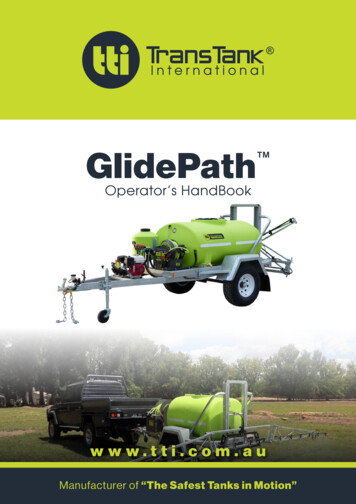
GlidePath Product HandBookPPE appropriate to the chemicals being used must be worn at all times when calibrating the GlidePath. As aminimum, the PPE should include coveralls, gloves and boots. A face shield and PVC apron are recommended.Calibration ProcedureCheck the label on the chemical container for the application rate and recommended spray nozzle type, referto Figure 2, which shows the TeeJet AIXR nozzle application chart. To apply a specific rate of chemical to thetarget surface, work out the: total sprayer output, travel speed, and the swath width.Using these parameters, the application rate is calculated as follows.Measure Total sprayer output [L/min]Set the pressure at the correct level for spraying determined by the type of nozzles. All nozzles used forspraying should be left on. For initial trials, set the pressure regulator at approximately 2 bar and adjust asneeded. Fill the spray tank with clean water, refer to Filling the GlidePath Tank procedure below. Run the sprayer atthe correct pressure with all nozzles operating. Place a measuring jug under first nozzle for one minute, then measure how much water is in the jug. Repeat for all nozzles. Nozzle output should not vary by more than 10%. If it does, the nozzle could beworn or damaged and should be replaced. Add all the jug measurements to find the total sprayer output in litres per minute.Measure the travel speed [km/h]The normal speed for spraying with small boom sprayers is 4–10 km/h. The slower the travel, the higher theapplication rate. Adjust travel speed to suit ground conditions. Measure how many seconds it takes to travel 100 metres with the sprayer attached and half full. Calculate your travel speed by inserting the time in seconds into the following formula: Travel speed (km/h) distance travelled in metres (say 100m) x3.6 / Time taken (in seconds)Calculate spray application rate [L/Ha]First, measure the swath width in metres. For general broadcast spraying, the swath width is equal to thenumber of nozzles multiplied by the nozzle spacing. For band spraying, the swath width is equal to the total ofall the band widths. Calculate the application rate using the following formula:Application rate (L/ha) (600 x total sprayer output (L/min)) / (swath width (m) x travel speed (km/h))Example: If total sprayer output is 5 L/min, speed is 8 km/h, and swath width is 4m, the application rate (600x 5 62.5 L/ha)/(4 x 8)If the application rate is less than specified, increase the pressure and repeat calibration to achieve the correctrate. Once the required rate is achieved, note the following parameters for future reference when using thisparticular chemical: Nozzle FittedType (Drop Size)Application RateSpray PressureForward Speed.w w w.tti.com. au91800 816 277
GlidePath Product HandBookFigure 2 – AIXR Application Chartw w w.tti.com. au101800 816 277
GlidePath Product HandBookGlidePath Operating InstructionsBefore First UseYour GlidePath Spray Trailer is delivered assembled and ready to be connected to your tow vehicle ortractor. Before use, it needs to be set up using the following instructions: Complete the warranty registration online at www.tti.com.au/warranty-registration, or use the WarrantyRegistration Card at the back of this handbook. Store this handbook, along with the Tank Quality Check Form and pump unit’s manual in a safe and easilyaccessible place for future reference.WARNING! The operator must fully understand all aspects of this handbook. Do notoperate the GlidePath unit if you are unfamiliar with its operation until you have readthis handbook. Read and thoroughly understand this handbook, paying particular attention to all safety requirements,before using the GlidePath for the first time. Check that all fittings, valves, hoses and electrical leads are secure following transit, and are notdamaged in any way. Inspect the tank for any damage or abrasions that may occur during transit.CAUTION! The GlidePath unit must be securely attached to the tow vehicle. Failureto do so may result in the unit breaking away from the moving vehicle. Warranty isconditional on the unit being correctly coupled. Connect the GlidePath to the tow vehicle, ensuring the tow hitch engages correctly and locks in place.Connect the safety chains using rated D-shackles. Connect the 7-pin trailer plug to the tow vehicle, ensuring it locks firmly. Check lights and indicatorsoperate correctly.CAUTION! Ensure any electrical connections are configured correctly to preventshorting or reverse polarity. Warranty is conditional on the electrical systems beingcorrectly connected. If optioned, install the remote control solenoid switch unit (Figure 3) at a suitable location near thedriver’s seat, then connect the cable to the vehicle’s power supply. Connect the other end to the solenoidswitch(es) at the regulator manifold.w w w.tti.com. au111800 816 277
GlidePath Product HandBookFigure 3 – Optional Remote Control Solenoid Operated Switch Units If the optional Foam Marker Kit is provided, install the electrical cable and connect it to the vehicle’s powersupply via the cable’s plug, refer to Figure 4.Figure 4 – Optional Foam Marker Kit Electrical Cables and Controller It is recommended that at first use, the GlidePath is filled with water for calibration purposes and for theoperator to become familiar with the characteristics of the unit. Refer to the Calibration Procedure to setup the unit for first use; and each time there are different spray parameters required.Filling the GlidePath TankWARNING! Ensure the filling area is in an open, well-ventilated space if filling withchemicals. Follow the instructions provided with the chemicals or the applicableSafety Data Sheet.Mixing and filling the GlidePath unit should be undertaken at a carefully chosen site, away from any risk ofspillages draining into water courses or into environmentally sensitive areas. Children and animals mustalways be kept away from mixing and filling operations.w w w.tti.com. au121800 816 277
GlidePath Product HandBookThe GlidePath’s tank is filled as follows:NOTE! Ensure the manually operated isolating valve for the boom is CLOSED. Check that the boom’s manual isolating valve is CLOSED, or the optional electrically controlled solenoidvalve is OFF. Open the tank filler by twisting and lifting the cap. Withdraw the internal basket strainer and inspect it for any debris. Clean it if required and reinstall it intothe top of the tank. Follow the chemical manufacturer’s instructions and safety precautions carefully, taking note of the orderin which the products are to be added to the tank. Measure the correct quantities of chemicals using clean measuring containers specifically for this purposeonly, then add the chemicals to the tank. Rinse out the measuring containers and any empty containers and pour all rinsing liquid into the GlidePathtank.CAUTION! Do not overfill the tank. This may result in chemical spillage.CAUTION! The GlidePath must never be left unattended while being filled with fluid. Top up the tank with water to the required level, ensuring it is not overfilled. Thoroughly mix the contents by stirring with a suitable paddle or starting the pump to allow recirculationthrough the pump and back into the tank. Ensure the hose operation lever is in the closed (BYPASS)position. Upon completion of filling the GlidePath tank, replace the filler cap and twist to tighten. Wash off any spillage from outside the tank. Close the chemical supply containers and store appropriately. Any empty containers must be thoroughlyrinsed and set aside for collection and disposal in compliance with environmental and work safetyrequirements.Operating InstructionsThe GlidePath is started and operated as follows: Confirm the tank contains the required chemical or water quantity.NOTE! Ensure the pressure regulator is set to the minimum position.w w w.tti.com. au131800 816 277
GlidePath Product HandBook At the pump, check that the pressure regulator is set to the minimum position by turning the knob anticlockwise, refer to Figure 5.Figure 5 – Pressure Regulator Optionsw w w.tti.com. au141800 816 277
GlidePath Product HandBook Check that the operation lever is in the closed (BYPASS) position. Check that the spray boom isolating valve(s) adjacent to the tank is in the CLOSED position. Open the ball valve on the tank’s discharge line. Start the pump using the following procedure: Turn the fuel lever to ON, refer to Figure 6. If the engine is cold, turn the choke lever to ON.CAUTION! Ensure the engine’s throttle is set to idle if the engine is cold.Do not adjust the throttle to maximum speed until the engine has warmedup. Set the throttle lever to idle for cold starting. If restarting a warm engine, the throttle can be left at normalengine operating speed. For a manual start engine, turn the power switch to ON. Pull the recoil starter handle until the enginestarts, then back off the choke lever to OFF. For an optional electric start engine, insert the key and switch the engine to ON and START. When theengine starts, release the key, which will return to the ON position. Back off the choke lever to OFF. Once the engine is warmed up, adjust the throttle to increase the engine speed to normal operating revs.With the engine running, the pump will operate with the fluid bypassing back into the GlidePath’s tank. When the engine needs to be stopped, turn the power switch to the OFF position.Figure 6 – Petrol Engine Start-up Procedure With the pump running, turn the pressure regulator knob clockwise to the required pressure –approximately 3 bar for spray boom operation. If the optional hose reel is fitted, approximately 5 bar isrequired for hose operation. Refer to the calibration procedure described above for the actual requiredpressure setting For spraying operations, refer to: Hose Spray Operation Spray Boom OperationIf the GlidePath is not going to be used within the next few hours, shut the system down by turning the engine’sfuel tap to OFF.w w w.tti.com. au151800 816 277
GlidePath Product HandBookHose Spray OperationSet up and operation of the optional 30m hose reel or 50m SuperReel spray system is conducted as follows:WARNING! Suitable PPE must be worn by the operator when conductingmanual hose spraying operations.WARNING! Do not spray in windy conditions, where spray driftcontamination may occur.Position the tractor with the GlidePath unit at a suitable point of the operations area.NOTE! Ensure the manually operated isolating valve to the boom isCLOSED. For the GlidePath fitted with manually operated spray booms, ensure the isolating valve on the pressureregulator manifold is in the CLOSED position. Check that the pressure regulator is set to its minimum setting. Start up the pump as detailed above. Thefluid will now be circulating through the system and returning to the tank via the bypass circuit. Set the pressure regulator to approximately 5 bar – this can be fine-tuned as required.CAUTION! Ensure not to over-run the hose when pulling it out from thereel, as this may damage the hose or the fittings. Pull the hose from the GlidePath’s optional hose reel to unwind it. Turn the operation lever from BYPASS to ON, which will now pressurise the hose. Aim the hose’s spray gun in the required direction and squeeze the trigger. Adjust the spray pattern byrotating the brass nozzle tip or gun lever, depending on spray gun type. Use a constant speed when spraying and release the trigger at the end of each swath or change ofdirection, to prevent overdosing. Work in parallel lines when spraying large areas, rather than swingingfrom side to side. At the end of the task, release the spray gun trigger and switch the operation lever to BYPASS. The fluidwill automatically recirculate through the system and return to the tank via the bypass circuit until thepump is switched OFF. Turn the pump OFF and then aim the spray gun in the required direction and squeeze the trigger. This willrelease the residual pressure in the hose, which will result in a small amount of fluid discharging. With the hose pressure released, the hose is ready to stow back on the GlidePath’s hose reel, refer toFigure 7. For the optional 30m reel, turn the handle at the side of the hose reel to wind it onto the spool,guiding the hose as necessary to ensure even distribution across the width of the reel. Allow enough slackin the hose to stow the spray gun in its holder on the side of the tank. The reel has a four-position lockingdevice to prevent the hose unwinding during transit. For the optional 50m SuperReel, press the button on the remote control supplied with the SuperReelto start retracting the hose, refer to Figure 8. The hose will wind on to the reel’s spool, guided by theintegrated fairlead. Release the button when the hose is retracted, allowing enough slack in the hose tostow the spray gun in its holder beside the SuperReel.w w w.tti.com. au161800 816 277
GlidePath Product HandBookFigure 7 – Optional 30m Hose ReelFigure 8 – Optional 50m SuperReelSpray Boom OperationWARNING! Before commencing spraying, plan the work effectively tominimise potential contamination of adjacent areas.The Spray Boom options supplied do not require any adjustments prior to operation once calibrated for thetask. The spraying operation is conducted as follows:WARNING! Do not spray in windy conditions, where spray driftcontamination may occur. Spray drift can be reduced by lower nozzleheight, lower pressures or by fitting larger nozzles. Position the vehicle at the starting point of the operations area. At the boom, fold out each of the two boom extensions fully, ensuring they each “click” into place at theend of their travel. Start the pump by following the procedure described above. The fluid will recirculate through the systemand return to the tank via the bypass circuit until the boom is set into operation. Set the pressure regulator to the correct setting as determined during calibration.w w w.tti.com. au171800 816 277
GlidePath Product HandBook At the pressure regulator manifold, turn the required valve(s) to ON, refer to Figure 5. Turn the operation lever from BYPASS to ON, or if supplied, from the driver’s seat, turn the option
Warranty 27 Warranty Policy 27 . Options Pinnacle Self-leveling steel booms, with 8m, 10m and 12m spray swath 30m hose on hose reel with spray gun 50m SuperReel with auto-rewind with spray gun Double-sided foam marker kit with solenoid control TeeJet Matrix 430 GPS Guidance System Remote control solenoid operated ON-OFF switch unit
![Index [beckassets.blob.core.windows ]](/img/66/30639857-1119689333-14.jpg)