Transcription
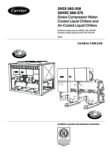
30GX 082-35830HXC 080-375Screw Compressor WaterCooled Liquid Chillers andAir-Cooled Liquid ChillersNominal cooling capacity 30HXC: 286-1300 kWNominal cooling capacity 30GX: 282-1203 kW50 HzGLOBAL CHILLERInstallation, operation and maintenance instructions
Contents1 - INTRODUCTION. 41.1 - Installation safety considerations. 41.2 - Equipment and components under pressure. 41.3 - Maintenance safety considerations. 41.4 - Repair safety considerations. 52 - Preliminary checks. 62.1 - Check equipment received. 62.2 - Moving and siting the unit. 73 - dimensions, clearances, weight distribution. 83.1 - 30HXC 080-190. 83.2 - 30HXC 200-375. 93.3 - 30GX 082-182. 103.4 - 30GX 207-358. 113.5 - Multiple chiller installation. 124 - Physical and electrical data for 30HXC units. 134.1 - Physical data 30HXC. 134.2 - Electrical data 30HXC. 134.3 - Electrical data, 30HXC compressors. 144.4 - Electrical data for 30HXC units with high condensing temperatures (option 150/150A). 144.5 - Unit characteristics for 30HXC units with very low temperature option (option 6). 155 - Physical and electrical data for units 30GX. 185.1 - Physical data 30GX. 185.2 - Electrical data 30GX. 185.3 - Electrical data, 30GX and 30HXC compressors, option 150 150A. 196 - Application data. 206.1 - Unit operating range. 206.2 - Minimum chilled water flow. 206.3 - Maximum chilled water flow. 216.4 - Variable flow evaporator. 216.5 - System minimum water volume. 216.6 - Cooler flow rate (l/s). 216.7 - Condenser flow rate (l/s). 216.8 - Evaporator pressure drop curve. 226.9 - Condenser pressure drop curve. 227 - ELECTRICAL CONNECTION. 237.1 - Electrical connections 30HXC units. 237.2 - Electrical connections 30GX units. 247.3 - Power supply. 257.4 - Voltage phase imbalance (%). 257.5 - Recommended wire sections. 278 - WATER CONNECTIONS. 298.1 - Operating precautions. 298.2 - Water connections. 308.3 - Flow control. 308.4 - Evaporator (and condenser for the 30HXC) water box bolt tightening. 318.5 - Frost protection. 318.6 - Operation of two units in master/slave mode. 312
9 - Major system components and operation data. 329.1 - Geared twin screw compressor. 329.2 - Pressure vessels. 329.3 - Electronic expansion device (EXV). 339.4 - Economizer. 339.5 - Oil pumps. 339.6 - Motor cooling valves. 349.7 - Sensors. 3410 - MAIN OPTIONS AND ACCESSORIES. 3510.1 - Compressor suction valves (option 92). 3510.2 - Compressor and evaporator noise insulation (30GX - option 14A). 3510.3 - Low-noise 30GX units equipped with acoustic panels (option 15). 3510.4 - Evaporator frost protection (30GX - option 41A). 3510.5 - Year-round operation of 30GX units (option 28). 3510.6 - Soft Start for 3- and 4-compressor 30HXC and 30GX units (option 25). 3510.7 - Electric protection level of the 30HXC control boxes to IP44C (option 20). 3610.8 - Tropicalised control box for 30HXC and 30GX units (option 22). 3610.9 - Brine units for low-temperature evaporator leaving applications (option 5). 3610.10 - Disassembled 30HXC units (option 51). 3610.11 - Available fan pressure of 150 Pa for 30GX units (option 12). 3611 - Maintenance. 3611.1 - Maintenance instructions. 3611.2 - Soldering and welding. 3611.3 - Refrigerant charging - adding charge. 3611.4 - Indication of low charge on a 30HXC system. 3711.5 - Electrical maintenance. 3711.6 - Pressure transducers. 3811.7 - Oil charging - low oil recharging. 3811.8 - Integral oil filter change. 3811.9 - Filter change-out schedule. 3811.10 - Filter change-out procedure. 3811.11 - Compressor replacement. 3811.12 - Corrosion control. 3911.13 - Condenser coil. 3912 - start-up ckecklist for 30HXC/GX Liquid chillers (use for job file). 40The cover illustrations are for illustrative purposes only and are not part of any offer for sale or contract.3
1 - INTRODUCTIONPrior to the initial start-up of the 30HXC/GX units, thepeople involved in the on-site installation, start-up, operationand maintenance of this unit should be thoroughly familiarwith these instructions and the specific project data for theinstallation site.The 30HXC/GX liquid chillers are designed to provide avery high level of safety during installation, start-up, operation and maintenance. They will provide safe and reliableservice when operated within their application range.This manual provides the necessary information to familiarize yourself with the control system before performingstart-up procedures. The procedures in this manual arearranged in the sequence required for machine installation,start-up, operation and maintenance.Be sure you understand and follow the procedures andsafety precautions contained in the instructions suppliedwith the machine, as well as those listed in this guide.To find out, if these products comply with Europeandirectives (machine safety, low voltage, electromagneticcompatibility, equipment under pressure etc.) check thedeclarations of conformity for these products.1.1 - Installation safety considerationsAfter the unit has been received, when it is ready to beinstalled or reinstalled, and before it is started up, it must beinspected for damage. Check that the refrigerant circuit(s)is (are) intact, especially that no components or pipes haveshifted (e.g. following a shock). If in doubt, carry out a leaktightness check and verify with the manufacturer that thecircuit integrity has not been impaired. If damage is detectedupon receipt, immediately file a claim with the shippingcompany.Do not remove the skid or the packaging until the unit isin its final position. These units can be moved with a forklift truck, as long as the forks are positioned in the rightplace and direction on the unit.The units can also be lifted with slings, using only thedesignated lifting points marked on the unit.These units are not designed to be lifted from above. Useslings with the correct capacity, and always follow thelifting instructions on the certified drawings supplied withthe unit.Safety is only guaranteed, if these instructions are carefullyfollowed. If this is not the case, there is a risk of materialdeterioration and injuries to personnel.Never cover any safety devices.This applies to the relief valve in the water circuit and therelief valve(s) in the refrigerant circuit(s).Ensure that the valves are correctly installed, beforeoperating the unit.4In certain cases the relief valves are installed on isolatingvalves. These valves are factory-supplied lead-sealed in theopen position. This system permits isolation and removalof the relief valves for checking and replacing. The reliefvalves are designed and installed to ensure protectionagainst overpressure caused by fire.All factory-installed relief valves are lead-sealed to preventany calibration change. If the relief valves are installed ona change-over manifold, this is equipped with a relief valveon each of the two outlets. Only one of the two relief valvesis in operation, the other one is isolated. Never leave thechange-over valve in the intermediate position, i.e. with bothways open (locate the control element in the stop position).If a relief valve is removed for checking or replacementplease ensure that there is always an active relief valve oneach of the change-over valves installed in the unit.The safety valves must be connected to discharge pipes.These pipes must be installed in a way that ensures thatpeople and property are not exposed to refrigerant leaks.These fluids may be diffused in the air, but far away fromany building air intake, or they must be discharged in aquantity that is appropriate for a suitably absorbingenvironment.Periodic check of the relief valves: See paragraph ‘Maintenance safety considerations’.Provide a drain in the discharge circuit, close to eachrelief valve, to avoid an accumulation of condensate orrain water.Ensure good ventilation, as accumulation of refrigerant inan enclosed space can displace oxygen and cause asphyxiation or explosions.Inhalation of high concentrations of vapour is harmful andmay cause heart irregularities, unconsciousness, or death.Vapour is heavier than air and reduces the amount of oxygen available for breathing. These products cause eye andskin irritation. Decomposition products are hazardous.1.2 - Equipment and components under pressureThese products incorporate equipment or components underpressure, manufactured by Carrier or other manufacturers.We recommend that you consult your appropriate nationaltrade association or the owner of the equipment or components under pressure (declaration, re-qualification, retesting,etc.). The characteristics of this equipment/these componentsare given on the nameplate or in the required documentation, supplied with the products.1.3 - Maintenance safety considerationsEngineers working on the electric or refrigeration components must be authorized, trained and fully qualified to do so.All refrigerant circuit repairs must be carried out by a trainedperson, fully qualified to work on these units. He must havebeen trained and be familiar with the equipment and theinstallation. All welding operations must be carried out byqualified specialists.
Any manipulation (opening or closing) of a shut-offvalve must be carried out by a qualified and authorisedengineer. These procedures must be carried out with theunit shut-down.NOTE: The unit must never be left shut down with theliquid line valve closed, as liquid refrigerant can be trappedbetween this valve and the expansion device. (This valveis situated on the liquid line before the filter drier box.)During any handling, maintenance and service operationsthe engineers working on the unit must be equipped withsafety gloves, glasses, shoes and protective clothing.Never work on a unit that is still energized.Never work on any of the electrical components, until thegeneral power supply to the unit has been cut using thedisconnect switch(es) in the control box(es).If any maintenance operations are carried out on the unit,lock the power supply circuit in the open position aheadof the machine.If the work is interrupted, always ensure that all circuitsare still deenergized before resuming the work.ATTENTION: Even if the compressor motors have beenswitched off, the power circuit remains energized, unlessthe unit or circuit disconnect switch is open. Refer to thewiring diagram for further details. Attach appropriatesafety labels.Operating checks:Important information regarding therefrigerant used: This product contains fluorinated greenhouse gascovered by the Kyoto protocol.Refrigerant type: R-134aGlobal Warming Potential (GWP): 1300 Periodic inspections for refrigerant leaks may berequired depending on European or local legislation.Please contact your local dealer for more information.During the life-time of the system, inspection and testsmust be carried out in accordance with nationalregulations.The information on operating inspections given in annexC of standard EN278-2 can be used if no similar criteriaexist in the national regulations.Safety device checks (annex C6 – EN 378-2): The safety devices must be checked on site once a yearfor safety devices (high-pressure switches), and everyfive years for external overpressure devices (safetyvalves). Check manual “30GX/30HXC Pro-Dialog Pluscontrol” for a detailed explanation of the highpressure switch test method.If the machine operates in a corrosive environment, inspectthe protection devices more frequently.Regularly carry out leak tests and immediately repairany leaks.1.4 - Repair safety considerationsAll installation parts must be maintained by the personnel incharge, in order to avoid material deterioration and injuriesto people. Faults and leaks must be repaired immediately.The authorized technician must have the responsibility torepair the fault immediately. Each time repairs have beencarried out to the unit, the operation of the safety devicesmust be re-checked.If a leak occurs or if the refrigerant becomes contaminated(e.g. by a short circuit in a motor) remove the completecharge using a recovery unit and store the refrigerant inmobile containers.Repair the leak detected and recharge the circuit with thetotal R-134a charge, as indicated on the unit name plate.Certain parts of the circuit can be isolated. If leaks occur inthese sections it is possible to top up the refrigerant charge.Refer to chapter 11.2 ‘Refrigerant charging - adding charge’.Only charge liquid refrigerant R-134a at the liquid line.Ensure that you are using the correct refrigerant typebefore recharging the unit.Charging any refrigerant other than the original chargetype (R-134a) will impair machine operation and can evenlead to a destruction of the compressors. The compressorsoperating with this refrigerant type are lubricated with asynthetic polyolester oil.Do not use oxygen to purge lines or to pressurize a machinefor any purpose. Oxygen gas reacts violently with oil,grease, and other common substances.Never exceed the specified maximum operating pressures.Verify the allowable maximum high- and low-side testpressures by checking the instructions in this manual andthe pressures given on the unit name plate.Do not use air for leak testing. Use only refrigerant or drynitrogen.Do not unweld or flamecut the refrigerant lines or anyrefrigerant circuit component until all refrigerant (liquidand vapour) has been removed from chiller. Traces ofvapour should be displaced with dry air nitrogen. Refrigerant in contact with an open flame produces toxic gases.The necessary protection equipment must be available,and appropriate fire extinguishers for the system and therefrigerant type used must be within easy reach.Do not siphon refrigerant.5
Avoid spilling liquid refrigerant on skin or splashing itinto the eyes. Use safety goggles. Wash any spills from theskin with soap and water. If liquid refrigerant enters theeyes, immediately and abundantly flush the eyes withwater and consult a doctor.Never apply an open flame or live steam to a refrigerantcontainer. Dangerous overpressure can result. If it isnecessary to heat refrigerant, use only warm water.During refrigerant removal and storage operations followapplicable regulations. These regulations, permitting conditioning and recovery of halogenated hydrocarbons underoptimum quality conditions for the products and optimumsafety conditions for people, property and the environmentare described in standard NFE 29795.Any refrigerant transfer and recovery operations must becarried out using a transfer unit. A 3/8” SAE connector onthe manual liquid line valve is supplied with all units forconnection to the transfer station. The units must never bemodified to add refrigerant and oil charging, removal andpurging devices. All these devices are provided with theunits. Please refer to the certified dimensional drawings forthe units.Do not drain water circuits containing industrial brines,without informing the technical service department at theinstallation site or a competent body first.Close the entering and leaving water shutoff valves andpurge the unit water circuit, before working on the components installed on the circuit (screen filter, pump, waterflow switch, etc.).Do not loosen the water box bolts until the water boxeshave been completely drained.Periodically inspect all valves, fittings and pipes of therefrigerant and hydronic circuits to ensure that they donot show any corrosion or any signs of leaks.2 - Preliminary checks2.1 - Check equipment received Do not re-use disposable (non-returnable) cylinders orattempt to refill them. It is dangerous and illegal. Whencylinders are empty, evacuate the remaining gas pressure,and move the cylinders to a place designated for theirrecovery. Do not incinerate.Do not attempt to remove refrigerant circuit componentsor fittings, while the machine is under pressure or while itis running. Be sure pressure is at 0 kPa before removingcomponents or opening a circuit.Do not attempt to repair or recondition any safety deviceswhen corrosion or build-up of foreign material (rust, dirt,scale, etc.) is found within the valve body or mechanism.If necessary, replace the device. Do not install safety valvesin series or backwards.ATTENTION: No part of the unit must be used as a walkway, rack or support. Periodically check and repair or ifnecessary replace any component or piping that showssigns of damage. The refrigerant lines can break under the weight and releaserefrigerant, causing personal injury. Do not climb on a machine. Use a platform, or staging towork at higher levels.Use mechanical lifting equipment (crane, hoist, winch, etc.)to lift or move heavy components. For lighter components,use lifting equipment when there is a risk of slipping orlosing your balance.Use only original replacement parts for any repair or component replacement.Consult the list of replacement parts that corresponds tothe specification of the original equipment.6Inspect the unit for damage or missing parts. If damageis detected, or if shipment is incomplete, immediatelyfile a claim with the shipping company.Confirm that the unit received is the one ordered.Compare the name plate data with the order.The unit name plate must include the followinginformation:Version numberModel numberCE markingSerial numberYear of manufacture and test dateRefrigerant used and refrigerant classRefrigerant charge per circuitContainment fluid to be usedPS: Min./max. allowable pressure (high and lowpressure side)TS: Min./max. allowable temperature (high andlow pressure side)Relief valve set pressurePressure switch cut-out pressureUnit leak test pressureVoltage, frequency, number of phasesMaximum current drawnMaximum power inputUnit net weightConfirm that all accessories ordered for on-siteinstallation have been delivered, and are completeand undamaged.Do not keep the 30HXC units outside where they areexposed to the weather, as the sensitive controlmechanism and the electronic modules may be damaged.The unit must be checked periodically during its wholeoperating life to ensure that no shocks (handling accessories,tools etc.) have damaged it. If necessary, the damaged partsmust be repaired or replaced. See also chapter “Maintenance”.
2.2 - Moving and siting the unit2.2.1 - MovingSee chapter 1.1 “Installation safety considerations”.Checks before system start-upBefore the start-up of the refrigeration system, the completeinstallation, including the refrigeration system must beverified against the installation drawings, dimensionaldrawings, system piping and instrumentation diagrams andthe wiring diagrams.2.2.2 - Siting the unitAlways refer to the chapter “Dimensions and clearances”to confirm that there is adequate space for all connectionsand service operations. For the centre of gravity coordinates,the position of the unit mounting holes, and the weight distribution points, refer to the certified dimensional drawingsupplied with the unit.Typical applications of these units are in refrigerationsystems, and they do not require earthquake resistance.Earthquake resistance has not been verified.CAUTION: Only use slings at the designated
30GX 082-358 30HXC 080-375 Screw Compressor Water-Cooled Liquid Chillers and Air-Cooled Liquid Chillers Nominal cooling capacity 30HXC: 286-1300 kW