Transcription
IntesisBox LG-AC-MBS-4/8/32/64Installation ManualSafety InstructionsWARNINGFollow carefully this safety and installation instructions. Improper work may lead to serious harmful for yourhealth and also may damage seriously the IntesisBox and/or any other equipment connected to it. IntesisBox must be installed by accredited electrician or similar technical personnel, following all the safety instructionsgiven here, and in accordance always with the country legislation for installation of electric equipment.IntesisBox can not be installed outdoors or exposed to direct solar radiation, water, high relative humidity or dust.IntesisBox must only be installed in a restricted access locationIn case of wall mount, fix firmly IntesisBox on a not vibrating surface following the instructions below.In case of DIN rail mount fix IntesisBox properly to the DIN rail following the instructions below.Mounting on DIN rail inside a metallic cabinet properly connected to earth is recommended.Disconnect always power of any wires before manipulating and connecting them to IntesisBox.A power supply with a NEC Class 2 or Limited Power Source (LPS) and SELV rated is to be used.Respect always the expected polarity of power and communication cables when connecting them to IntesisBox.Supply always a correct voltage to power IntesisBox, see details of voltage range admitted by the device in the technicalcharacteristics below.This device was designed for installation in an enclosure. To avoid electrostatic discharge to the unit in environments withstatic levels above 4 kV precautions should be taken when the device is mounted outside an enclosure. When working inan enclosure (ex. making adjustments, setting switches etc.) typical anti-static precautions should be observed beforetouching the unit.Installation instructions Disconnect from mains the power supply before connecting it to IntesisBox.Disconnect power of any bus or communication cable before connecting it to IntesisBox.Mount IntesisBox on the wall or DIN rail following the instruction given below, respecting the safetyinstructions given above.Connect a NEC Class 2 or Limited Power Source (LPS) and SELV rated power supply to IntesisBox,respect the polarity if DC power or Line and Neutral if AC power. Apply always a voltage within the rangeadmitted by IntesisBox and of enough power (see technical characteristics).Circuit-breaker must be used before the power supply. Rating 250V-6AConnect the communication cables to IntesisBox, see details on the user's manual.Power IntesisBox and the rest of devices connected to it.Configuration and setupUse the software LinkBoxMB to configure IntesisBox, follow the instructions of the user's manual for moredetails.See instructions to download and install the latest version of LinkBoxMB andthe user's manual athttp://www.intesis.com/down/mb/linkboxmb.html Intesis Software S.L. - All rights reservedThis information is subject to change without noticeIntesisBox is a registered trademark of Intesis Software m 34 9380471341/5
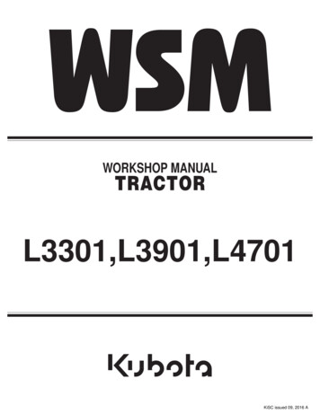
IntesisBox LG-AC-MBS-4/8/32/64Installation ManualWall mount1.Separate the fixing clips in the bottom of the box, pushing them to the outside until hear the "click" whichindicates that now the clips are in position for wall mount, see in the figure below.Bottom view of the boxClips in their original position, for DIN railmount2.Clips in position for wall mountUse the holes of the clips to fix the box in the wall using screws. Use the template below for the wall holes.61 mmTop view of the boxØ 3 mmIntesisBox 100 mmwww.intesisbox.comDIN rail mountWith the clips of the box in their original position, insert first the box in the upper edge of the DIN rail and later insertthe box in the down part of the rail using a small screwdriver and following the steps n the figure below.Side view of the box1DIN Rail32 Intesis Software S.L. - All rights reservedThis information is subject to change without noticeIntesisBox is a registered trademark of Intesis Software m 34 9380471342/5
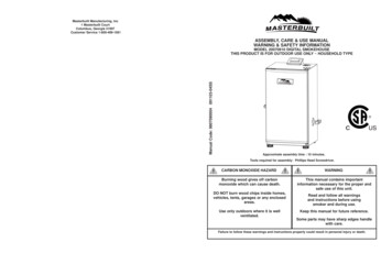
IntesisBox LG-AC-MBS-4/8/32/64Installation ManualConnectionsModbus TCPmasterSee Note 2To Power supplySee Note 1EthernetRJ45To LG InterfaceEIA485See Note 3- CMN 24Vac9 - 30VdcMax.125 mA24VacMax.127mA50-60HzEIA232EthernetModbus TCP EIA485LG PI485IntesisBox www.intesisbox.comModbus RTUEIA485- EIA232LinkBoxMBPC ConsoleOnly for configurationSee Note 4Modbus RTUmaster EIA485See Note 2Modbus RTUmaster EIA232Console.Standard cable 1.8 m.DB9 female - DB9 male.Supplied with IntesisBox.See Note 2Notes:1.Must use NEC Class 2 or Limited Power Source (LPS) and SELV rated power supply.If using DC power supply: Respect polarity applied of terminals ( ) and (-). Be sure the voltage applied is within the range admitted (9 to 30 Vdc).The power supply can be connected to earth but only through the negative terminal, never through the positive terminal.If using AC power supply: Make sure the voltage applied is of the value admitted (24 Vac). Do not connect any of the terminals of the AC powersupply to earth, and make sure the same power supply is not supplying any other device.2.Modbus connection. Only one Modbus connection type can be used simultaneously, Modbus TCP, Modbus RTU EIA485, or Modbus RTUEIA232, this must be configured within LinkBoxMB software. Modbus TCP: Connect the cable coming from the Modbus TCP master device to the connector ETH of IntesisBox, use a crossoverEthernet CAT5 cable if connecting directly to the Modbus TCP master device, or a straight Ethernet CAT5 cable if connecting to aswitch or hub of the LAN of the building. If connecting using the LAN of the building contact the network administrator and makesure that TCP/IP traffic and the TCP port used (502 by default) are allowed through all the LAN path.Modbus RTU EIA485: Connect the EIA485 bus to the connector Modbus RTU EIA485 of IntesisBox. Respect the polarity.Remember the characteristics of the standard EIA485 bus: maximum distance of 1200 meters, maximum 32 device connected,and a 120 ohms terminator resistor in each end of the bus. IntesisBox comes with an internal bus biasing circuit which incorporatesinternal bus terminator resistor, and thus if you connect IntesisBox in one end of the bus then it is not necessary to install additional120 ohms resistor in that end.Modbus RTU EIA232: Connect the serial EIA232 cable coming from the Modbus RTU master device to the Modbus RTU EIA232connector of IntesisBox, this is a male DB9 connector (DTE) in which only lines TX, RX and GND are used, see pinout details inthe user's manual. Respect the maximum distance of 15 meters for this EIA232 line.3.LG AC system’s connection through (PMNFP14A0, PMNFP14A1 or PHNFP14A0) EIA485 interface board or Outdoor Unit PI485connection. Connect the EIA485 bus of LG boards to the connector LG PI485 of IntesisBox. Respect the polarity. Remember thecharacteristics of the standard EIA485 bus: maximum bus distance of 1200 meters, maximum 32 devices in the bus, and atermination resistor of 120 ohms in each end of the bus. IntesisBox incorporates and internal circuit for bus biasing with terminationresistor incorporated, so if IntesisBox is installed in one of the ends of the bus it is not necessary to connect an additional terminationresistor in that end.4.Use the software LinkBoxMB to configure IntesisBox. Consult the user's manual for details. Intesis Software S.L. - All rights reservedThis information is subject to change without noticeIntesisBox is a registered trademark of Intesis Software m 34 9380471343/5
IntesisBox LG-AC-MBS-4/8/32/64Installation ManualTechnical characteristicsEnclosureColorPowerTerminal wiring(for power supplyand low-voltagesignals)MountingModbus TCP portModbus RTU portsLG AC portLED indicatorsConsole rationalhumidityProtection1Plastic, type PC (UL 94 V-0).Dimensions: 107mm x 105mm x 58mm.Light Grey. RAL 7035.9 to 30Vdc /-10%, Max.: 125mA.24Vac /-10% 50-60Hz, Max.: 127mAMust use a NEC Class 2 or Limited Power Source (LPS) and SELVrated power supply.Plug-in terminal block for power connection (2 poles).Per terminal: solid wires or stranded wires (twisted or with ferrule)1 core: 0.5mm2 2.5mm22 cores: 0.5mm2 1.5mm23 cores: not permittedWall.DIN rail EN60715 TH35.1 x Ethernet 100Base-T (RJ45).1 x Serial EIA232 (DB9 male DTE). SELV1 x Serial EIA485 (Plug-in screw terminal block 2 poles). SELV1 x EIA485. Plug-in screw terminal block (2 poles). SELV1 x Power.2 x Serial port Modbus RTU activity (Tx, Rx).2 x Serial port LG AC activity (Tx, Rx).2 x Ethernet port Modbus TCP link and activity (LNK, ACT).EIA232. DB9 female connector (DCE). SELVVia console port.1Allows upgrades via console port.0 C to 70 C5% to 95%, non-condensingIP20 (IEC60529).Standard cable DB9male-DB9female 1,8 meters long is supplied with the device for connection to a PC COM port forconfiguring and monitoring the device. The configuration software, compatible with Windows operating systems, is alsosupplied. Intesis Software S.L. - All rights reservedThis information is subject to change without noticeIntesisBox is a registered trademark of Intesis Software m 34 9380471344/5
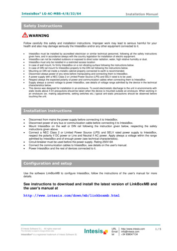
IntesisBox LG-AC-MBS-4/8/32/64Installation ManualDimensionsPower Ethernet portExternal dimensionsEIA485portModbusRTU portsConsoleport58 mm105 mm107 mmFree space recommended for device installaion, with spacing enough for external connections.100 mm130 mm115 mm Intesis Software S.L. - All rights reservedThis information is subject to change without noticeIntesisBox is a registered trademark of Intesis Software m 34 9380471345/5
IntesisBox LG-AC-MBS-4/8/32/64 Installation Manual 1. Separate the fixing clips in the bottom of the box, pushing them to the outside until hear the "click" which indicates that now the clips are in position for wall mount, see in the figure below. 2. Use the holes of the clips to fix the box in the wall using screws.