Transcription
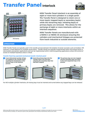
INTERLOCK CONTROL PANELInstallation of all electrical devices shouldbe completed by licensed electricians andall electrical connections should meet OSHA &MSHA Regulations for local and federal codes.LUBE OIL INTERLOCK PANELINTRODUCTIONmotor getting energized. It also has a “post-lubetimer” that continues operation of the lube oilsystem motor for six (6) plus minutes while thecrusher motor is powering down and slowing to astop. It also provides a properly sized starter for theCEMCO oil system motor. Optional starters canalso be purchased for Oil heaters and/or Oil coolersif they are needed.VIBRATION SWITCH MODEL ANDOPERATIONELE-365 Interlock PanelThe CEMCO, Inc. ELE-0365 interlock panel is asafety control system that provides protection forthe vital crusher components. There are a numberof safety features that are equipped standard withCEMCO VSI Crushers. When a safety element isactivated or “tripped”, a corresponding functionlight on the lube oil panel (Vibration, Oil flow,Oil level) will turn off (or on) and the crusher willshut down to prevent damage to the crusher andits vital components.CEMCO standard IMI vibration switchThe IMI vibration switch comes standard with allCEMCO crushers. They are classified as three (3)inch per second (IPS) range of movement models.The vibration switch has an internal and an externalreset button. The vibration switch operates on120Vac power, it also has a 4-20mA output point topower to vibration display on the interlock panel.The IMI vibration switch also has two relays that“alert” and/or “alarm” the interlock panel basedon vibration values from the vibration sensor. The“alert” relay will turn on a light on the lube oil panelto warn the operator that an elevated amount ofvibration is occurring with the crusher. The “alarm”relay will activate an electrical “shut down” modein the interlock panel to protect the crusher andprevent any damage. Both the “alert and “alarm”The interlock panel also includes both a “prerelays need a120 Vac power source to operatelube timer” that ensures lubrication to the crusher correctly. This power source can be provided bypedestal for three (3) minutes prior to the crusher “jumping” the common power block to the “Alert”The interlock panel also provides electricalconnection points to attach all of the field wiringsafety devices. This provides a single powersource for all the field devices such as the oilsystem motor, oil flow meter, oil level switch,crusher vibration switch with warning relay(Alert) and vibration shut down (Alarm).22
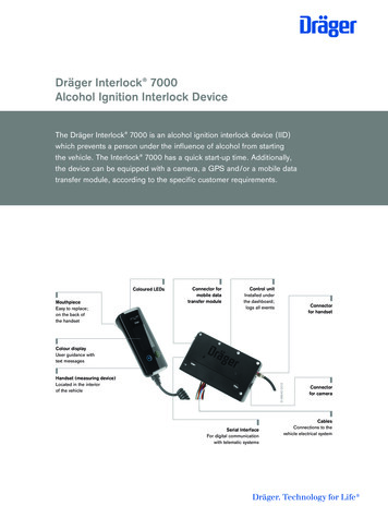
INTERLOCK CONTROL PANELand the “Alarm” relay connection points on thevibration switch. The signal can then be connectedback to the interlock panel via terminals T-16 /T-17.during operation. Adjustments need to be madefor different materials and locations. The usercan also record the vibration readings to trendmaintenance for replacement of wear parts on thecrusher. It can also be used to see if a warninglight was due to some surge of material going in tothe crusher, or if the warning is something worseand the operator needs to shut down the plant tosee what the problem is.Internal wiring for vibration switch4-20mA DISPLAYThe 4-20mA display gives the user a numericalvalue of the vibration that is occurring withincrusher.ELE-365 Alert and Alarm LightsThe vibration display is connected in the vibrationswitch by the use of shielded cable to the 4-20mAterminal. The shielded cable needs to be runin a separate conduit or raceway to preventElectromagnetic Interference (EMI) from otherelectrical sources. In certain installations a filter or“ferrite suppression cores” may be needed if thedisplay is not reading correctly due to the distancefrom the vibration switch to the interlock panellocation. This will need to be determined at timeof installation.Listed on the next table are a scale of mA to IPSfor a 3 IPS switch and a percentage of the IPS tomA.4-20mA vibration displayThis numerical value will allow the operator toadjust the crusher vibration switch (Alert & Alarm)to optimal settings for the crusher and structure23
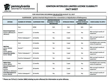
INTERLOCK CONTROL PANELDIP SWITCH & POTENTIOMETERPOSITIONINGThe dip switches, located inside the vibrationswitch in the lower area of the housing, need tobe placed the LAT, EN, EN & OFF (All down)position.The 4-20mA is a value of the IPS of vibration switchALERT AND ALARM CONNECTIONRELAYSall dip switches in the down positionThe “alert” and “alarm” set points are adjustedvia the single turn potentiometers.The vibration switch has two relays to warn (Alert)and to shut down (Alarm) the crusher. The warningrelay (Alert) will turn on the orange “VibrationAlert” light mounted on the interlock panel.The shut down relay (Alarm) will turn on the red“Vibration Alarm” light and disable the crusher.The “Alert” relay needs to be connected terminalpotentiometers for Alarm and AlertT16 in the interlock panel. The “Alarm” relayneeds to be connected to terminal T17 in theThe potentiometers are used to adjust theinterlock panel.vibration switch sensitivity and the time delay(TD) allowed in that movement for the “alert”and “alarm”. The alarm relay is set using thefirst potentiometer labeled Alarm SP and the alertrelay is set with using the third potentiometerlabeled Alert SP. The alert relay trips whenthe set percentage of the alarm value hasbeen reached. Time delays for both functionsare controlled using the second and fourthpotentiometers labeled Alarm TD & Alert TDalert and alarm relay diagram24Example: The alarm is set for 1 IPS and the alertis set for 50% for 10 seconds then the warning- alert light will turn off at ½ IPS at 10 secondswarning you that the crusher has met a value of
INTERLOCK CONTROL PANELvalues are activated the switch needs to be resetat the crusher. This is so that the operator will goand check the crusher for any problems and resolveIf both criteria’s for alert and alarm are met at the them before starting the crusher up and doing moredamage to the crusher or its components.same time, then both actions will occur. Thesealerts can inform the operator that wear partsOlder model (3IPS) vibration switches have anneed to be replaced due to wear, or tramp ironinternal reset button. The vibration switch must becould be entering the crusher, or there is a feedphysically opened to access the rest button and resetmaterial surge in the system.the vibration switch. If you utilize the test feature besure to reset the vibration switch before you attemptVIBRATION SWITCH TEST AND RESET.to operate the crusher.The vibration switch also has both a “test” and“reset” button located in the right side of the case. LUBE OIL PANEL POWER SUPPLYThe top right is the reset and the bottom rightThe ELE-354 oil lube panel has a 480Vac to 120Vacbutton is utilized to test the vibration switch.transformer supplied in to the lube panel box topower the field devices. The transformer uses aFLM-6/10 time delay fuse.vibration that should be inspected to protect thecrusher’s vital components.There are three (3) LED lights in the vibrationswitch case. The two upper left lights are the“alert” and “alarm” the lower right lights ispower. Both the alert and the alarm lights shouldbe off unless the switch has been tripped or thetest button has been used.TEST: The test button is utilized to verify thatthe vibration switch is functioning correctly andto simulate an alarm / alert trip. By pressing thetest button you will activate both alarm / alertvalues at the same time simulating a “trip”.RESET: The current vibration switches hasan external reset button. If the alarm or alertThe red terminal blocks are 120vac and whiteterminal blocks are your neutral 120v power supplyfor the field devices. There are also terminal blocksfor each phase of the 480 Vac to use for starting theoptional oil cooler and/or oil heater.When wiring the field devices to the interlockpanel you will supply the devices power fromthe red terminal blocks to the device and yourneutral/ control wire back to the corresponding fieldterminal.25
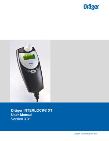
INTERLOCK CONTROL PANELExample: oil level switch takes a 120vac from thered terminal block to one of the Blue wires. Theother blue wire will become #14 and you will runa line back to Terminal-14 in the field terminals.When the oil level is made the contact will closesignaling back to the relay.supply your own brand of VFD or soft start referto the manufactures service manual for properelectrical connection locations.CEMCO crushers are directional specific, whenstarting up a new crusher or doing any sortof electrical modification to motors on and existinginstallation, ALWAYS CHECK THE DIRECTION OFROTATION. Failure to do so will result in crusherdamage and will void CEMCO warranty.V-TWIN CRUSHER DUAL DRIVE WIRINGSCHEMATICSTERMINAL LISTING(Terminal 14) Oil Level, (Terminal 15) Oil Flow,(Terminal 16) Vibration Alert (Terminal 17)Vibration Alarm, (Terminal 18) Oil Cooler 86 F,(Terminal 19) Oil Heater, and (Terminal 21) hightemp warning 178 F.If you are using the interlock control box with adual drive V-Twin crusher, you will need to add aDPDT relay to start both drives.* See Schematics for suggested wiring. Each plantand local code has its own specific requirementsthat need to be accounted for. This is a suggestedschematic, Always refer to local codes and plantrequirements and always use licensed electricians. *(Terminal 66-67) are for the Soft Start or a VFDremote start control wires. ( if you have a V-Twincrusher see dual drive wiring schematics, a DPDTrelay will need to be added to start both VFD’s )VARIABLE FREQUENCY DRIVE (VFD) ORSOFT START OPERATIONA VFD or soft start control is required tocorrectly operate / start the VSI crusher motor.The blue terminal blocks are controllingconnection points for use with a Variablefrequency drive (VFD) or a soft start to properlycontrol the crusher motor.CEMCO can supply Danfoss VFD or WorldWide soft start Automation Drives. When usinga CEMCO supplied Danfoss VFD to start thecrusher motor, the lube oil panel control wireslabeled 66, 67 must be connected to terminal12.18 of the VFD. This VFD wire connection isrequired for the proper start / stop function andoperation of the crusher motor. If you chose to26Dual drive wiring diagramCEMCO recommends using DanFoss Drives, ifyou choose to use a DanFoss Drive, the followingparameters will need to change to use the DanFossVFD relay. Go to Parameter 5-40 and change thesetting to “9 Alarm”. Do this on both drives. Thiswill shut down both drives and force the user to fixthe alarm from the tripped drive. {a copies of thisschematic is are in the back of this manual and inthe control box as well}. If using another branddrive or soft start check with that manufacturer tosee how best to use its spare internal relay.
INTERLOCK CONTROL PANEL27
INTERLOCK CONTROL PANEL28
INTERLOCK CONTROL PANEL29
power to vibration display on the interlock panel. The IMI vibration switch also has two relays that "alert" and/or "alarm" the interlock panel based on vibration values from the vibration sensor. The "alert" relay will turn on a light on the lube oil panel to warn the operator that an elevated amount of vibration is occurring with .