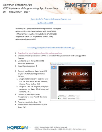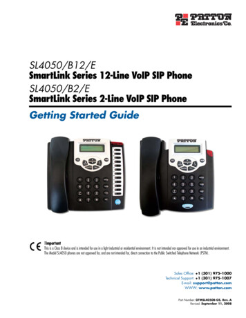
Transcription
SmartLink Box User ManualDocument DataDocument TitleFile NameStatusStatus: preliminarySmartLink Box User ManualSmartLink Box User Manual CE FCC v3.51.docfinal draftiiVersion: 3.5
SmartLink Box User ManualTABLE OF CONTENTS1INTRODUCTION . 12FUNCTIONAL DESCRIPTION . 22.12.2SIGNALLING . 2CARD/TERMINAL INTERFACE, GENERAL . 22.2.1 CARD/TERMINAL INTERFACE, ANALYSE MODE . 32.2.2 CARD/TERMINAL INTERFACE, INTERCEPT MODE . 32.2.3 CARD/TERMINAL INTERFACE, CARDREADER MODE. 3BOX / DRIVER INTERFACE . 42.3.1 SPECIFICS . 42.3.2 ANSWER TO RESET . 42.33TECHNICAL DESCRIPTION . 53.13.2CARD / TERMINAL INTERFACE. 53.1.1 ANALYSE MODE . 53.1.2 INTERCEPT MODE . 53.1.3 CARDREADER MODE . 5DRIVER INTERFACE . 54PROTOCOL DESCRIPTION. 64.14.24.34.4NODE ADRESSING . 6COMMUNICATION SCENARIOS . 6EVENTS . 8COMMANDS . 94.4.1 RESET BOX .114.4.2 RESET TIMESTAMPS .114.4.3 SET TIMESTAMPS .114.4.4 SET RELATIVE TIMESTAMPS .114.4.5 SET CLOCKFREQUENCY .114.4.6 SET CLOCKFREQUENCY EXTENDED .114.4.7 SET INTERCEPT MODE.124.4.8 SET ANALYSE MODE .124.4.9 SET CARDREADER MODE .124.4.10 SET PROTOCOL TIMEOUT .124.4.11 SET BOX BAUDRATE .124.4.12 SET PARITY MODE .124.4.13 SET FORCE PARITY SIGNAL .124.4.14 SET T MODE .124.4.15 SET DIVIDER .134.4.16 SET DIVISION RATE .134.4.17 SET GUARDTIME.134.4.18 SET CONVENTION .134.4.19 SET ATR CHARACTER DELAY .13Status: preliminaryiiiVersion: 3.5
SmartLink Box User Manual4.54.4.20 SET TIME OUT .134.4.21 NO DIRECTION SWITCH .144.4.22 SET TIME OUT EXTENDED .144.4.23 PRESET DIVIDER 1 .144.4.24 PRESET DIVIDER 2 .144.4.25 SET DEFAULT DIVIDER .144.4.26 SET NO PPS .144.4.27 SET FORCE PAR COUNT .144.4.28 SET FORCE PAR NUMBER .154.4.29 SET ATR1 .154.4.30 SET ATR2 .154.4.31 SET TRIGGER COUNT.154.4.32 SET DELAYED RESPONSE .154.4.33 SET PAR ERROR NUMBER.154.4.34 SET TRIGGER OUT EVENT .164.4.35 SET ATR DELAY .164.4.36 SET RESPONSE DELAY.164.4.37 EXTEND PAR SIGNAL TIMING .164.4.38 EXTEND GUARDTIME.164.4.39 INITIALIZE CARD .174.4.40 DEINITIALIZE CARD.174.4.41 SWITCH CLK .174.4.42 CLK OFF LEVEL .174.4.43 RESET CARD .174.4.44 SET SUPPLY VOLTAGE .174.4.45 SET VCC THRESHOLD .174.4.46 SET TIMESTAMP EOT .174.4.47 GET TIMESTAMP .184.4.48 GET MODE .184.4.49 GET PROTOCOL TIMEOUT .184.4.50 GET SOFTWARE VERSION .184.4.51 GET DIVISION RATE .184.4.52 GET TERM STATUS.184.4.53 GET CARD STATUS .184.4.54 GET CLOCK FREQUENCY .184.4.55 GET BAUDRATE .194.4.56 GET SUPPLY VOLTAGE.194.4.57 GET VCC THRESHOLD .194.4.58 GET ATR CHARACTER DELAY .194.4.59 GET GUARDTIME .194.4.60 GET ATR1 .194.4.61 GET ATR2 .194.4.62 GET ATR DELAY.194.4.63 GET TIMEOUT EOT .194.4.64 GET CPLD VERSION .194.4.65 START SOFTWARE DOWNLOAD .194.4.66 START CPLD DOWNLOAD .194.4.67 PROGRAM CPLD .19COMMAND REPLIES . 20Status: preliminaryivVersion: 3.5
SmartLink Box User Manual5APPENDIX . 215.1FCC STATEMENT . 21Status: preliminaryvVersion: 3.5
SmartLink Box User Manual1INTRODUCTIONIn June 1998, Collis started the development of a hardware interface that should facilitate the useof Collis‟ generic test-tool “Conclusion Smartlink” for testing SmartCards and SmartCardterminals. The result of this effort, the “Conclusion Smartlink Box” has been in use since early1999.Because of the rapid development in SmartCard technology, the original hardware no longer meetsthe demands placed on it by today‟s market. For example, it is not possible to use the device tocommunicate with terminal/card combinations that work at 3V supply voltage, commonly used inGSM.Therefore a decision has been made to design a new version of the SmartLink Box that does meetthese demands and is also more flexible and easier to upgrade. This document is the basis for thisnew hardware design.Status: preliminary1/21Version: 3.5
SmartLink Box User Manual2FUNCTIONAL DESCRIPTIONThe CIB-1894 (Chipcard Interface Box, hereafter referred to as: “the box”) is a microprocessorcontrolled interface between Conclusion Smartlink (herafter referred to as: “the driver”) and achipcard / terminal that facilitates monitoring and/or modification of the communication betweencard and terminal. It is also possible to simulate the behaviour of either a card or a terminal.The interface should be designed to work with all SmartCards and terminals currently in use andalso –as much as possible- be prepared for future card/terminal combinations, in as far as this iscompatible with the current ISO standards.2.1SignallingThe following events / statuses will be signalled by LEDs:ItemDescriptionLED colorPower OnThe presence of supply voltage to the boxgreenCard InsertedA card being fully inserted into the card slotyellowVccThe presence of supply voltage on the card interfaceredCLKThe presence of a clock signal on the card interfaceredRSTThe presence of a RST signal on the card interface 1redCard I/OThe presence of activity on the I/O line of the card 2greenTerminal I/OThe presence of activity on the I/O line of the terminal 2greenTable 2-1 Signals2.2Card/terminal interface, generalThe box has three fundamental modes on the card/terminal interface: The Analyse Mode, theIntercept Mode, and the Cardreader Mode. In Analyse Mode there is a direct connection betweencard and terminal and the communication between them is merely monitored. In Intercept Mode,the communication between the card and the terminal is diverted via the driver, which enablesmodification of messages. In Cardreader Mode, all connections between card and terminal areseparated and the card receives all necessary electrical signals from the box itself.In Analyse and Intercept Mode the box wil automatically determine the frequency of the CLKsignal as soon as the presence of VCC is detected. It will then continuously measure the CLKfrequency and compare it to the previously measured frequency, so as to determine and signal anychanges.1The RST LED is on when the RST signal is low, i.e. the card is in Reset.In Analyse Mode these LEDs signal the origin of the communication. In Intercept Mode they show onwhich interface the communication is taking place.2Status: preliminary2/21Version: 3.5
SmartLink Box User ManualThe following events are automatically tracked and signalled to the driver: Insertion and removal of a card(event 0xB1, resp. 0xB0) Application and removal of supply voltage (Vcc)(event 0xA1, resp. 0xA0) Application of RST to the card(event 0xAF) CLK signal stop(event 0xAA) CLK signal (re)start(event 0xAB) Clockfrequency change(event 0xAC) Signaling of a Parity error by card or terminal(event 0xC0)It will be possible to introduce Parity errors while sending data to the card or the terminal, in orderto analyse the response to this. The result of the Parity check on received characters will be sent tothe driver.2.2.1Card/terminal interface, Analyse ModeIn this mode all elektrical signals between the terminal and the card are functionally, though notphysically, connected to eachother. The box will measure the supplyvoltage and clockfrequencypresented by the terminal and determine the communication bitrate based on the clockfrequencyand a divisor, preset by the driver. These parameters can be queried by the driver.The box receives the data being sent between the terminal and the card and monitors the directionof this communication. The data received is sent directly to the driver, with information addedabout the message originator (card or terminal), possible parity errors and an optional timestamp.An end-of-message is determined by either a change in the direction of the communication or apreset timeout.2.2.2Card/terminal interface, Intercept ModeThis mode also connects all electrical signals between the terminal and the card, with the exceptionof the I/O line. As in Analyse Mode, the box will measure suplyvoltage and clockfrequency anddetermine the correct bitrate.Upon release of the RST line, the box will send a string of characters, preset by the driver, to theterminal. This string will usually be the same as the ATR of the card that is used. The subsequentcommand received from the terminal will be sent to the driver, not the card. The driver will thensend this command, or a modified version of it, to the card. The box will send the answer from thecard to the driver, which then sends it to the terminal, et cetera.Error signalling on the I/O line, as defined by ISO 7816-3, § 6.1.3, will be detected and signalled tothe driver. The affected byte will be resent. Send Parity errors can be forced from the driver.This mode is independent of the presence of a card and can therefore be used to completelysimulate the behaviour of a card towards the terminal.2.2.3Card/terminal interface, Cardreader ModeIn this mode there is no connection between the card and the terminal. All elektrical signals arepresented to the card by the the box itself. The driver can set the supply voltage, theclockfrequency and the bitrate divisor. Error signalling on the I/O line, as defined by ISO 7816-3,§ 6.1.3, will be detected and signalled to the driver. The affected byte will be resent. Send Parityerrors can be forced from the driver.Status: preliminary3/21Version: 3.5
SmartLink Box User Manual2.3Box / driver interfaceThe interface between box and driver is primarily responsible for the transmission and reception ofthe datastream between terminal and card. This interface is also used to set and query boxparameters and status.The interface protocol will be a superset of that designed for the CIB-3580 (the first version of thebox).The interface will guarantee data transmission at a speed that is sufficient to enable Interceptionwithout problems caused by waiting times being too long. To this end, the data shall be sent in astreaming fashion, which means that every character received from the terminal or card shall bedirectly transmitted to the driver rather than the whole message being buffered.To ensure data integrity, the interface shall implement hardware flow control to prevent bufferoverflow.Lastly, it will be possible to upload new firmware to the box, using this interface. From version2.0.0 onwards, it will also be possible to reprogram the CPLD.2.3.1SpecificsThe original design (2001) of the driver interface was based on an RS-232 connection. Since then(late 2003), a version (CIB-3390) has been released that uses USB. On the driver ( PC) side, this isstill seen as a COM port, because the USB-driver supplied implements a Virtual Com Port (VCP).At protocol level however, the two versions (RS-232 and USB) are identical.In contrast with all previous versions, the latest versions (CIB-189x) are powered by the USB.2.3.2Answer To ResetAs with a card, the box issues an Answer To Reset (ATR) string, on power-up as well as onreception of the RESET BOX command. This ATR is of the following format:CCS xxxx Version y.y.ywhere xxxx denotes the type of interface, i.e. 3390 is the „old‟ USB version and 1890 is the USBpowered 1.8V version. 1894 is the high speed version.y.y.y denotes the firmware version.Although the box types are compatible at protocol level, their firmware is different and should notbe mixed, because this will render the box useless.Status: preliminary4/21Version: 3.5
SmartLink Box User Manual33.1TECHNICAL DESCRIPTIONCard / terminal interfaceTo ensure operational compatibility with as many combinations of card / terminal as possible, thecard and terminal interface will comply with these specifications:3.1.1Analyse Mode1.2.3.4.5.6.7.8.9.3.1.2Supplyvoltage (VCC) from terminal:Voltage differential VCC (terminal - card):“1” level on I/O line (transmission):“0” level on I/O lijn (transmission):“1” level on I/O lijn (reception):“0” level on I/O lijn (reception):Clockfrequency (fCLK):Bitrate on I/O:I/O signal delay (terminal - card):1.65 VDC – 5.5 VDC50 mV max.3 VCC – 0.2 V0.4 V maximummin. 0.75 * Vccmax. 0.25 * Vcc2 kHz – 30MHz41.25 Mbps maximum100 ns maximumIntercept ModeThe same specifications apply as for Analyse Mode.3.1.3Cardreader Mode1.2.3.4.5.6.7.8.3.2Supplyvoltage (VCC) :Maximum current :“1” level on CLK, RST and I/O line:“0” level on CLK, RST and I/O line:Clockfrequency (fCLK):CLK signal dutycycle:CLK signal risetime:Bitrate on I/O:1.6 VDC – 5.5 VDC 2%50mA VCC – 0.2 V0.4 V maximum500 kHz – 24 MHz45 – 55% 5 ns1.25 Mbps maximumDriver interfaceThe Box contains a (USB 2.0 compliant) USB-to-UART bridge, which is seen as a Virtual COMPort on the driver side. The interface is set to communicate at 500,000 bps, irrespective of theCOM Port setting. Other parameters are: 8 databits, Even Parity, 1 Stop-bit. The interface useshardware flow-control.3The voltage supplied to the card is internally limited to 5.5V. A terminal supply voltage larger than this willtherefore result in a larger differential.4The minimum frequency is determined by the response of the „clock present‟ detector. The maximumfrequency that can be measured is 32.767MHz. The serial receiver and transmitter remain functional at 60MHzStatus: preliminary5/21Version: 3.5
SmartLink Box User Manual4PROTOCOL DESCRIPTIONThe box and the driver communicatie through a full-duplex connection. Full-duplex is necessarybecause both the box and the driver must be able to send data at any given time. This means thattwo communication sessions can be in progress simultaneously; one initiated by the box and oneby the driver.Each message consists of a Protocol Address and Control byte (PAC), one or more data fields andone or more Control byte(s). Among other things, the Control byte contains a More Data flag thatindicates if any datafields will follow. A Control byte always relates to the previous Data byte.PACDATCONTROL(1)DATCONTROL(0)For the protocol type PAC-LEN-DATA (bit PAC.0 eaqual to 0), each message contains 3 fields:PAC field, length field (LEN), data field (DAT).When bit b8 of the most significant byte of the length field is set to 0, the length field consists ofonly one byte. Bits b7 to b1 code the number of bytes of the value field. The length field is withinthe range 1 to 127.When bit b8 of the most significant byte of the length field is set to 1, the subsequent bits b7 to b1of the most significant byte code the number of subsequent bytes in the length field. Thesubsequent bytes code an integer representing the number of bytes in the value field. Two bytesare necessary to express up to 255 bytes in the value field.PAC4.1LENDATNode adressingFour nodes must be adressed: Box Card Terminal DriverTwo bits can identify a node, so one nibble can be used to specify both sender and receiver.4.2Communication scenariosThe following communication scenarios can be distinguished: Commands to the box from the Driver Messages from the Terminal sent to the Driver by the box Messages from the Card sent to the Driver by the box Messages from the Driver sent to the Terminal through the box Messages from the Driver sent to the Card through the boxThe box will send either a command response or an ACK message in response to every commandsent by the driver. Messages from the driver to the card or the terminal will only be replied to bythe receiver concerned.Status: preliminary6/21Version: 3.5
SmartLink Box User ManualProtocol address and control byte (PAC)76 5 43 2 10Protocol TypeSend sequence numberCommunication session numberTimeStamps on/offReceive address (bit 0)Receive address (bit 1)Send address (bit 0)Send address (bit 1)Node address nibble7 6 5 40011XXXX0101XXXXXXXX0011XXXX0101Sender is BoxSender is CardSender is TerminalSender is DriverReceiver is BoxReceiver is CardReceiver is TerminalReceiver is DriverProtocol control nibble3 2 1 0XXXXXX01XXXX01XXXX01XXXX01XXXXXXProtocol type PAC-LEN-DATAProtocol type PAC-DATA-CONTROLCurrent sequencenumber is 0Current sequencenumber is 1Session initiated by BoxSession initiated by DriverTimeStamp not presentTimeStamp followsControl byte76 5 43 2 10More DataRFURFURFUParity error signal forced on received byteParity signal detectedParity ResendParity Error7 6 5 4 3 2 1 0X X X X X X X 0X X X X X X X 10 X X X X X X X1 X X X X X X X1 0 X X X X X X1 1 X X X X X XStatus: preliminaryLast byte sentMore data to followWhen sending Box - Driver: Databyte from card/terminal received with correct parityWhen sending Driver - Box: Send databyte to card/terminal with correct parityWhen sending Box - Driver: Databyte from card/terminal received with incorrect parityWhen sending Driver - Box: Send databyte to card/terminal with incorrect parityResend with correct parityWhen sending Driver - Box: Send databyte to card/terminal with incorrect parityResend with incorrect parity7/21Version: 3.5
SmartLink Box User Manual4.3EventsCertain events are outside the control of the box and the driver, because they are determined bythe user or the terminal. Examples of such events are the insertion of a card and a change inclockfrequency. Because it would take too much time to let the driver poll these events, the boxwill send them asynchronously. These events are as follows:EventVcc not presentVcc presentCLK stopCLK startCLK frequency changedRST activeCard removedCard insertedParity error detectedProtocol xDFTable 4-1 EventsStatus: preliminary8/21Version: 3.5
SmartLink Box User Manual4.4CommandsThe following commands will be supported by the box:Command 5OpCodeData 6Unit 7Range 8RESET BOX0x00N/AalwaysRESET TIMESTAMPS0x01N/AalwaysSET TIMESTAMPS0x02uchar0/10alwaysSET RELATIVE TIMESTAMPS0x03uchar0/10Intercept andCardreader ModeSET CLOCKFREQUENCY0x04ucharx 50 kHz20 200SET CLOCKFREQUENCY EXTENDED0x05uintx 1 kHz500 24000SET INTERCEPT MODE0x08N/ASET ANALYSE MODE0x0CN/ASET CARDREADER MODE0x0DN/ASET PROTOCOL TIMEOUT0x0EucharSET BOX BAUDRATE0x0Fuchar0 80SET PARITY MODE0x10uchar0/11alwaysDefault valueApplicable 9always3579alwaysalways*alwaysalwaysms.1 25alwaysalwaysSET FORCE PARITY SIGNAL0x11uchar0/10Intercept andCardreader ModeSET T MODE0x12uchar0/10alwaysSET DIVIDER0x13uint1 1023372alwaysSET DIVISION RATE0x14uchar0 30alwaysSET GUARDTIME0x15uint1 655233alwaysSET CONVENTION0x16uchar0/10alwaysSET ATR CHARACTER DELAY0x17uintetu1 655233alwaysSET TIME OUT0x18ucharetu0 25527alwaysNO DIRECTION SWITCH0x19N/ASET TIME OUT EXTENDED0x1AuintPRESET DIVIDER 10x1BPRESET DIVIDER 20x1CetuIntercept Modeetu0 6552327alwaysuint1 1023372alwaysuint1 1023372alwaysCommands in bold italics are new compared to the previous version. Sending a command not listed in this table will result in theerrormessage “Unknown Command” (see Command replies)6N/A no data should be sent with the command. uchar is an Unsigned Char (1 byte; value 0 255), uint an Unsigned Integer (2 bytes;0 65535) and ulong an Unsigned Long (4 bytes; 0 232 – 1). Multi-byte parameters are in Big Endian format.7Etu is the “Elementary Time Unit” as defined by ISO7816. A “character” is a character as sent on the I/O line between card andterminal and is 12 etus long8Sending data outside the specified range will lead to the errormessage “Out Of Range” (see Command replies). An exception is madefor commands that require a 0/1 parameter. Here, all values not equal to „0‟ are considered „1‟ and will be accepted.9Sending a non-applicable command will result in the errormessage “Command Not Valid” (see Command replies)5Status: preliminary9/21Version: 3.5
SmartLink Box User ManualCommand 5OpCodeData 6SET DEFAULT DIVIDER0x1DuintSET NO PPS0x1EN/AUnit 7Range 8Default valueApplicable 91 1023372alwaysoffcharactersSET FORCE PAR COUNT0x1FucharSET FORCE PAR NUMBER0x20ucharSET ATR10x21char[32] empty SET ATR20x22char[32] empty characters0 25501 2551alwaysIntercept andCardreader ModeIntercept andCardreader Mode0 255 empty alwaysalwaysIntercept andCardreader ModeIntercept andCardreader ModeSET TRIGGER COUNT0x25ucharSET DELAYED RESPONSE0x26char[32]SET ATR DELAY0x2Auintetu1 6552312alwaysSET RESPONSE DELAY0x2Buintetu1 6552312Intercept andCardreader ModeINITIALIZE CARD0x30N/ACardreader ModeDEINITIALIZE CARD0x31N/ACardreader ModeSWITCH CLK0x32uchar0/1CLK OFF LEVEL0x33uchar0/1RESET CARD0x34N/A empty Cardreader Mode0Cardreader ModeCardreader ModeSET SUPPLY VOLTAGE0x36ucharx 100 mV.0 55 and„0xFF‟SET VCC THRESHOLD0x37ucharx 100mV.10 4524alwaysSET TIMESTAMP EOT0x38uchar0/10alwaysGET TIMESTAMP0x41uintGET MODE0x48ucharGET PROTOCOL TIMEOUT0x4EucharGET SOFTWARE VERSION0x51ucharGET DIVISION RATE0x53uint0 1023alwaysGET TERM STATUS0x60uchar0xA0 0xA1alwaysGET CARD STATUS0x70uchar0xB0 0xB1alwaysGET CLOCK FREQUENCY0x64ulongHz0 32x106alwaysGET BAUDRATE0x65ulongbpsGET SUPPLY VOLTAGE0x66uintx 100 mV0 63alwaysGET VCC THRESHOLD0x67ucharx 100mV.10 45alwaysGET ATR CHARACTER DELAY0x78uintetu1 65523alwaysGET GUARDTIME0x79uintetu1 65523alwaysGET ATR10x71char[32]alwaysGET ATR20x72char[32]alwaysGET ATR DELAY0x7AuintStatus: preliminary10/21x 100 µs.ms.50always0 65535always0 2always0 25alwaysalwaysetualways1 65523alwaysVersion: 3.5
SmartLink Box User ManualCommand 5OpCodeData 6Unit 7Range 8GET TIMEOUT EOT0x7Buintetu0 65523GET CPLD VERSION0x7Cuchar[3]START SOFTWARE DOWNLOAD0xAAalwaysSTART CPLD DOWNLOAD0xCCalwaysPROGRAM CPLD0xCDalwaysDefault valueApplicable 9alwaysalwaysTable 4-2 Command set4.4.1RESET B
Card I/O The presence of activ ity on the I/O line of the card 2 green Terminal I/O The presence of activity on the I/O line of the terminal 2 green Table 2-1 Signals 2.2 Card/terminal interface, general The box has three fundamental modes on the card/terminal interface: The Analyse Mode, the Intercept Mode, and the Cardreader Mode.
