Transcription
AC 2008-2307: RAPID PROTOTYPING IN THE DESIGN METHODOLOGYSerdar Tumkor, Stevens Intitute of TechnologySerdar Tumkor is affiliated with Design and Manufacturing Institute at Stevens Institute ofTechnology as a Research Scientist. He has been an Assistant Professor of MechanicalEngineering at Istanbul Technical University since 1996. Dr. Tumkor received his PhD inMechanical Engineering from Istanbul Technical University in 1994. He has taught MachineDesign, Engineering Design, and Computer-Aided Technical Drawing courses. His currentresearch interests include systematic design, design for sustainable products, design fordisassembly and recovery, computer aided design & manufacturing, process planning and rapidprototyping/manufacturing.Kishore Pochiraju, Stevens Institute of TechnologyKishore Pochiraju is the Director of Design and Manufacturing Institute and an AssociateProfessor in Mechanical Engineering at Stevens Institute of Technology, Hoboken, NJ. Hereceived his PhD from Drexel University in 1999 and joined Stevens after a postdoctoralappointment at the Center for Composite Materials, University of Delaware. Dr. Pochiraju worksin the areas of multi-scale and multi-physics mechanics of composites And structures. His recentfunded research on oxidation and durability of high temperature polymer Matrix composites. Hehas developed and taught courses on modeling and simulation, finite element methods,composites and most recently on intelligent mechatronic systems.Page 13.1017.1 American Society for Engineering Education, 2008
RAPID PROTOTYPING IN THE DESIGN METHODOLOGYAbstractThe main objective of a design course is to teach a procedure to practice the fundamentalengineering knowledge as repeatable design techniques. A popular approach to teachundergraduate engineering design is by solving open ended design problems. Tools are availablenow to students allowing them to evaluate the cost, manufacturing, usability, and environmentalconsequences of their designs. However aesthetical success of the design can only be verifiedsubjectively and cannot be imagined from 2D drawings or 3D models. Observing and touchingthe products prototype may help overcome this obstacle. Rapid prototyping (RP) techniquesallow creation of prototypes in short amount of time. RP enables realization of a design andpromotes the enthusiasm and motivation in students. This paper describes the visualization of thedesign ideas and the position of the RP in the design methodology.1. IntroductionDesign as activity involves creativity and innovation but it is constrained by high quality and lowcost to meet customer expectations. Customers are increasingly demanding both innovation andvalue. Methodological design courses exist in engineering education with the objective ofteaching engineering design fundamentals. A popular approach to teach undergraduateengineering design is through a structured, problem solving method that students use to tackleopen-ended design problems1-4. Classical engineering design process5 has the following generalsteps,1) Recognition of need2) Definition of Problem,3) Synthesis,4) Analysis & Optimization,5) Evaluation,6) Presentation.The native language of design has evolved from the technical drawing to a 3D model. Ability tovisualize the ideas and communication among design teams are possible with visual-spatialperception of the design concepts. The visualization of technical artifacts started with scratchedstone tablets, continued freehand sketches on papyrus or paper and with digital age and CAD ithas advanced to another level6. Solid models provide the ability for easy modification and enablestructural/thermal analysis and simulations. Another advantage is that the traditional tasks of adesigner, drafter, analyst, and prototype maker may be all performed by a single engineer usingdigital engineering design tools. Digital 3-D models can be easily shared and accessed throughweb-based tools on the internet, which provide a collaborative design environment forgeographically distributed design teams7. Next step for design visualization and verification isRapid Prototyping (RP), which started a few years ago but stumbled because of the large capitalinvestments required and hidden expenses for the consumables8.Page 13.1017.2
2. Process of Realizing a Rapid PrototypeSketching is a natural language of creative ideation, and is always one of the earliest steps of theengineering design process. Freehand sketching is very useful on this first stage to visualize theideas and concepts. While computer sketching may be more accurate than manual freehandsketching, the quirks and complexity of learning sketching software may hinder creativity.Computer aided parametric modeling in design starts with a two dimensional (2D) sketch on aplanar grid. Computer drawing software offers a variety of 2D primitive elements, such as line,circle, rectangle, arc, spline, and ellipse. In order to complete 2D profiles (section of the part),the software includes 2D editing functions such as extend, trim, mirror, offset, and array.Parametric dimensions and other geometric constraints are then added to the profile to initiallyfix the geometry. When a 2D sketch is complete, it is then either extruded or revolved to formthe three dimensional (3D) model of the part. More 2D sketches can be created on the workplanes, and these secondary profile sketches can then be used to cut through the base part or toadd more material. Design features, such as fillets, rounds, chamfers, ribs, bosses, cuts, andholes, are also available with simple commands that do not require sketches. Parametric solidmodeling has following advantages:1) Accurate description of the part/concept/idea2) Easier to find errors and solution3) Fast calculations of the consequences and simulation4) Easy modification of the model5) Direct data transfer for the CAM.Currently, the ability to use a 3D parametric solid modeling software package has become one ofthe standard tools acquired by mechanical engineering graduates. 3D solid modeling allowsdesigner to rotate, zoom or pan the graphics on the screen. These visual objects give himimmediate and satisfactory feedback of his work. But, again some feeling is missing. Sinceaesthetical success of the design needs to be verified by ones mind, nothing can replace a reelprototype. It is not easy to build a prototype for a student with his limited experience andknowledge. Advances in rapid prototyping technology allow them to produce inexpensiveprototypes from the 3D solid models. Some universities have provided facilities for students toproduce rapid prototypes of their design concepts. Once the 3D geometry of the model has beenconstructed, a rapid prototype of the individual parts can be made. Most of the softwarepackages give the user ability to save the parts in stereolithography (STL) file format. This STLformat approximates the surfaces of a solid model with triangular facets. The STL file isinterpreted by the RP machine and parts produced layer by layer deposition or etching.3. Rapid Prototyping EquipmentPage 13.1017.3Rapid Prototyping refers to the automatic construction of physical objects using solid freeformfabrication directly from a CAD model. The first equipments for rapid prototyping becameavailable in the late 1980s and were used to produce models and prototype parts. Today, a largenumber of equipments are available in the marketplace. They are used for a much wider range ofapplications and are even used to manufacture production fully functional parts in relativelysmall numbers. Additive methods join together liquid, powder or sheet materials to formcomplex parts layer by layer, their main differences are found in the way layers are built to create
parts. Some are melting or softening material to produce the layers (SLS, FDM) where othersare laying liquid materials thermosets that are cured with different technologies.Different techniques are,‚ Melting, Solidifying/Fusing‚ Cutting, gluing/joining‚ Joining, binding‚ Photo curingo One Lasero Multi lasero Masked lampThe major rapid prototyping methods and the names of the developers are listed in Table 1.Process nameStereolithography(SLA)Selective LaserSintering (SLS)Solid GroundCuring(SGC)Laminated ObjectManufacturing(LOM)Fused DepositionModeling (FDM)3 D PrintingForming agentlaserMaterialpolymerDeveloper3D Systems9 , EOS10Laser3D Systems, EOSlaserPolymer, metal,ceramicPhotopolymer, liquidmonomer, waxPaper, polymerExtrusionPolymer, ABSStratasysLiquid adhesiveMIT, ZCorp-Inkjet Printing-Jetted photopolymerLiquid jetsUV lightMetal, ceramic aspowderAcrylics, ElastomericPhotopolymerUV lightCubital11Helisys, CubicTechnologies123D SystemsObjet13Table 1 Major RP MethodsThe first and most known RP process is Stereolithography (SLA) was developed by 3D Systemsof Valencia, California, USA, founded in 1986. A vat of photosensitive resin contains avertically-moving platform. The part under construction is supported by the platform that movesdownward by a layer thickness (typically about 0.1 mm / 0.004 inches) for each layer. A laserbeam traces out the shape of each layer and hardens the photosensitive resin. It provides thegreatest accuracy with an excellent surface finish. SLA parts are durable and these functionalparts are suitable for wide variety of applications e.g. pre production, Product verification,Form/Fit/function testing, Snap fit assemblies, thin walled parts.Page 13.1017.4Selective Laser Sintering (SLS) process primarily used to rapidly produce 3D prototypes, parts,tools, direct mold inserts, or lost-wax casting patterns. SLS process provides durable, metal,plastic or rubber like prototypes directly from CAD model. These prototypes can be used as test
parts for form, fit and function. SLS technology provides broad range of materials e.g. rigidthermoplastics, stainless steel, polystyrene, thermoplastic elastomers, cast form plastic for lostwax casting process.Solid Ground Curing (SGC) was developed and sold by Cubital. While the method offered goodaccuracy and a very high fabrication rate, it suffered from high acquisition and operating costsdue to system complexity. This led to poor market acceptance. Cubital is a spin-off companyfrom Scitex Corporation. While the company no longer exists and its intellectual property hasbeen acquired by Objet Geometries, Ltd., it's still an interesting example of the manytechnologies other than stereolithography that utilize photopolymer materials14. Cubital's SGCsystem was an additive process that uses ultraviolet (UV) light to selectively cure thin layers ofliquid monomer. The primary material is photopolymer resin, and the secondary material is wax.In the Laminated Object Manufacturing (LOM) process profiles of object cross sections are cutfrom paper or other web material using a laser. The paper is unwound from a feed roll onto thestack and first bonded to the previous layer using a heated roller which melts a plastic coating onthe bottom side of the paper. The models are created layer-by-layer and have the look of woodbefore they are sealed with protective lacquer. The process is commonly used for creating largesand casting patterns.Fused Deposition Modeling (FDM) is the second most widely used rapid prototypingtechnology, after stereolithography. The system consists of a build platform, extrusion nozzle,and control system. A plastic filament supplies material to an extrusion nozzle. The nozzle isheated to melt the plastic and has a control system which allows the flow of the melted plastic tobe turned on and off. The nozzle is mounted to a mechanical stage which can be moved in bothhorizontal and vertical directions. As the nozzle is moved over the table in the requiredgeometry, it deposits a thin bead of extruded plastic to form each layer. The plastic hardensimmediately after being squirted from the nozzle and bonds to the layer below. The entire systemis contained within a chamber which is held at a temperature just below the melting point of theplastic. The cross section quickly solidifies, and the platform descends where the next layer isextruded upon the previous layer. This continues until the model is complete.3D Printing is the less costly process of rapid prototyping which turns the 3D CAD data toquickly produce a three dimensional model. Where an ordinary printer lays down a single 2Dlayer of ink on a sheet of paper, these printers add the extra dimension by printing layer afterlayer until you have a real, 3d object similar to your CAD model. This process was developed atMIT. It's often used as a direct manufacturing process as well as for rapid prototyping. Mono/multi ink jets deposit melted material or adhesive material on a powder chamber. The processstarts by depositing a layer of powder object material at the top of a fabrication chamber. Thejetting head deposits liquid adhesive in a 2D pattern onto the layer of the powder. To accomplishthe part layer by layer, a measured quantity of powder is first dispensed from a similar supplychamber by moving a piston upward incrementally. The roller then distributes and compressesthe powder at the top of the fabrication chamber.Page 13.1017.5Materials used in these methods are SLA, (laser cured epoxy), SLS, (laser sintered polymer),FDM, (molten polymer layering), LOM, (bonded paper layering). Industrial materials can be
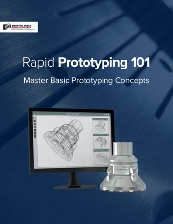
used with FDM and SLS and fully functional parts can be produced in small batch sizes.Sometimes prototypes from solid block of metal or plastic block can be manufactured by CNC toget the maximum strength. This called subtractive method for RP15.4. Role of Rapid Prototyping in Redesign of Products for New RequirementsAs a component of engineering design education in Engineering Design course (MAK 422E),students must undertake a project that includes the redesign of a product. The main redesignobjective is to make them lighter and stylish namely travel-friendly. For this purpose thestudents are divided into design teams of five to seven members, which aids in innovativethinking and concept generation16-18. The emphasis is to redesign home appliances with theobjective to make them attractive for frequent travelers. Home appliances like electric irons andkettles were chosen for the study. The students, in the course, are expected to progress throughthree phases of product development study, which can be listed as clarification of thetask/specification, conceptual design and embodiment. These steps can be redefined in theaspect redesign since redesign is the detailed study and analysis of an existing product to collectinformation, remake the design decisions and improve the product designed initially by theoriginal design team. (Figure 1) It is an iterative procedure that consists of information,definition, innovation, evaluation and presentation steps.Searching for customer needs and market analyses initiate the effort of redesigning the product.By using these information and market analysis data, the teams have to prepare a shortrequirement list as a kickoff document. However, not to limit the creativity of the team membersthe requirement list can be modified during the redesign project. This also maintains the openended nature of the design processPage 13.1017.6
ExistingProductRecognition of NeedAssignmentAnalyze Failures & Disturbing F actorsInformationClarify and Define the TaskRequirementListSystematic Prediction ofFunction & PrinciplesDefinitionSearching PrincipleSolutionEstablish FunctionStructureSearching for thefunction carriersList of Part/SubassembliesSearching Redesign ConceptsInnovationSearching ConceptsConceptsEvaluationIdentify Evaluation CriteriaRapid Prototyping of ConceptsEvaluation of the ConceptsTechnical DocumentationPresentationPresentationFigure 1 Redesign Steps in the CoursePage 13.1017.7After systematic prediction of the functions and searching for principle solutions that fulfill theneeds in the requirement list, a function structure can be established. The intention in thisactivity is to fully understand the physical principles and design parameters for the product. Areverse engineering study of the existing product is undertaken by carrying out the disassemblyof the product. This disassembly step helps the student in understanding the actual function and
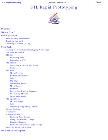
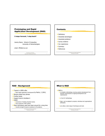
form of the product and each component as well. Modeling and analysis of the existing productwill give the students the chance to create new ideas.Figure 2 Hand Sketches and 3D solid models used in the Gallery MethodAfter the student have an understanding of the existing product, the idea generation step forredesign is done, where every team members is encouraged to independently generate theirconcepts. The students are free to make hand sketches or parametric solid models that can bemodified to express their ideas (Figure 2). Design ideas/concepts are evaluated with criteria ofthe cost, manufacturing, usability, and environmental consequences. Selected concepts areprototyped and observed for aesthetic verification (Figure 3).Page 13.1017.8
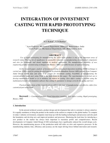
Figure 3 Evaluation of the ConceptsStudents were able to choose PTC ProE Wildfire or Solidworks as 3D modeling software (Figure4). Created 3D models are converted to STL files and transferred to the ZCorps 3D printer(Figure 5). RP used at least once by each design group under supervision of a technician or aTA. The project ends with a final report and presentation of the concepts developed by eachteam.Figure 4 3D CAD models in Solidworks and ProE Wildfire and converted STL FilesPage 13.1017.9
Figure 5 Transferring STL file to the 3D printer using ZprintFor products with human interfaces such as the electric iron, ergonomic ease of use cannot bereliably established with 3D Models. Full scale rapid prototypes enable determination of usercomfort. For example, the handle of the electric iron in Figure 5, requires enough clearance forhuman hands to hold and work with the iron. The distribution of weight and grip comfort can beeasily evaluated with a full-scale non-functional prototype.To evaluate the effectiveness of the course and the projects, the students were asked toprovide feedback what they found most beneficial outcome in this course and what they wouldrecommend changing.The following is a summary of the responses:‚ Most valuable benefit was learning how to work as a team and feel the responsibility.‚ I learned about sustainability.‚ I learned how an engineering design project is prepared.‚ I did not realize that the recognition of the need and problem definition so important inthe product design.‚ We learned the importance of communication and reporting among the team members forthe success.‚ Construction of a prototypical product was critical in the redesign process.‚ More time is needed for better presentations.5. Concluding remarksPage 13.1017.10Rapid prototyping was incorporated as a key segment in a design project students learnedto work in a group and assumed different roles to complete redesign of typical home appliancesfor new requirements. All students expressed their design concepts individually using graphicsand prototypes. They used intuitive and conventional methods like brainstorming, 6-3-5 method,gallery method, etc., so they evaluated and improved their concepts. During the development ofthe redesign project, students learned have to deal with issues on planning and clarifying task,conceptual design, embodiment design and detailed design, step by step. They realized how to
consider the design criteria such as design for minimum cost, design for environment, design formanufacturability etc. They also experienced and appreciated creation of prototypes forpresentation of concepts and for testing the human interfaces of the .14.15.16.17.18.Pahl, G. and Beitz, W., Engineering Design, Springer-Verlag, London, 1984.Ullman, D.G., The Mechanical Design Process, McGraw-Hill, New York, 1992.Ertas A., Jones J.C., “Engineering Design Process”, John Willey and Sons, 1997Dieter G., “Engineering Design”, McGraw-Hill, 1993.Shigley, J. E. & C. R. Mischke, 1989, Mechanical Engineering Design, 5th. ed., McGraw-Hill, New York.Harris, L.V.A. and Meyers F., “Graphics: Into the 21st Century”, ASEE 07 American Society for EngineeringEducation Annual Conference & Exposition, AC2007-327.Tumkor, S., Fidan, I., “Collaborative Product Development on the Internet” DES033/Proceedings ofESDA2002, 6th Biennial Conference on Engineering Systems Design and Analysis, Istanbul, Turkey, July 8-11,2002.Wohlers, T., T.Grimm, “The Real Cost of Rapid Prototyping”, Time-Compression Technologies, March/April2002 available on the internet at: http://www.tagrimm.com/information/articles.html3D Systems (2008) available on the internet at: http://www.3dsystems.com/EOS (2008) available on the internet at: http://www.eos.info/products/Cubital (2008) available on the internet at: http://home.att.net/ castleisland/sgc.htmCubic Technologies (2008) available on the internet at: http://www.cubictechnologies.com/Helisys.htmObjet (2008) available on the internet at: http://www.2objet.com/Castle Island Co., The Rapid Prototyping Patent Museum, (2008) available on the internet at:http://home.att.net/ rppat/museum/mus 2.htmKalpakjian, S., S.R. Schmid, (2005) Manufacturing Engineering and Technology, PEARSON PrenticeHall,pp.582S. Tumkor, Ali Imre Aydeniz, Ismail Fidan, “Teamwork and Gallery Method in Engineering Design Project”,CD Proceedings of the 2004 American Society for Engineering Education Annual Conference & Exposition,Salt Lake City, UT, June 20-23, 2004Petry, E. and Mahaffey, F., 2003, Team Projects Team Teaching Team Building, American Society forEngineering Education Annual Conference & Exposition, Session 3548Qammar H. K, Michael C. H.,. Evans E. A, Broadway F. S., Ramsier R. D., “Focusing on Teamwork VersusTechnical Skills in the Evaluation of an Integrated Design Project”, Proceedings of the 2003 American Societyfor Engineering Education Annual Conference & Exposition, June 22-25, Nashville, TNPage 13.1017.11
knowledge. Advances in rapid prototyping technology allow them to produce inexpensive prototypes from the 3D solid models. Some univ ersities have provided f acilities for students to produce rapid prototypes of their design concepts. Once the 3D geometry of the model has been constructed, a rapid prototype of the individual parts can be made.