Transcription
Wireless Backhaul Topologies:Analyzing Backhaul TopologyStrategiesRon Nadiv, VP Technology & System EngineeringTzvika Naveh, Director of Network SolutionsAugust 2010Ceragon Networks , CeraView , FibeAir and the FibeAir design mark are registered trademarks of CeragonNetworks Ltd., and Ceragon , PolyView , ConfigAir , CeraMon , EtherAir , QuickAir , QuickAir PartnerProgram , QuickAir Partner Certification Program , QuickAir Partner Zone , EncryptAir and Microwave Fiber are trademarks of Ceragon Networks Ltd. All rights reserved.
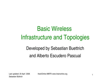
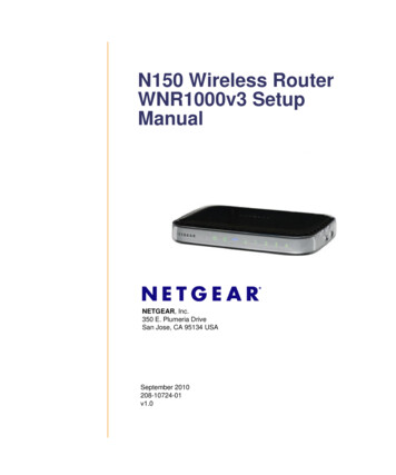
IntroductionThe demand for new high-speed mobile data services has causednetwork planners to re-evaluate backhaul capacity requirements andTDM-to-packet migration plans. The planning process must takecomplex network topology considerations into account.In this paper, we focus on microwave-based backhauling topologies.Selecting the right topology for wireless backhaul networks is anespecially complicated task. Here, we take a close look at the pros andcons of tree and ring topologies, with special attention to costconsiderations. We provide a case study based on the mobilebackhauling requirements of a large Latin American mobile provider,and explain how the Ceragon FibeAir IP-10 microwave backhaulingplatform provides an ideal solution, offering excellent adaptability to avariety of topological models.Backhaul TopologiesThere are many parameters to be considered when selecting a network topology, and evenmore when it comes to radio networks – where Line-Of-Sight (LOS), rain zone and otherpropagation factors are taken into account, as well as infrastructural considerations such asantenna sites and towers. The common topology choices for radio networks are trees or rings,or a combination of both. The tree topology in itself is a combination of two other basictopologies – the chain and the star, as shown below in Figure 1.Figure 1: Common Backhaul Network TopologiesStar topologies use a separate link from a hub to each site. This is very simple, but inefficientfor microwave systems, as it requires longer radio links and an LOS for each link (which maybe impossible). The star topology also makes for very poor frequency reuse, since all thelinks originate at the same point, and interference is more likely to occur between links usingthe same frequency.WHITE PAPER Wireless Backhaul Topologies: Analyzing Backhaul Topology Strategies2
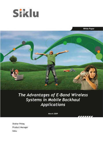
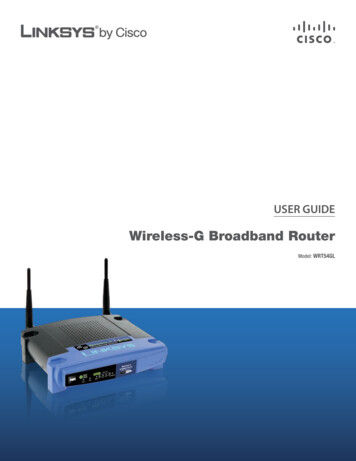
In chain topologies, all sites reside on a single path – solving the problems inherent to startopologies, but resulting in a very sensitive topology in which the first link malfunction cancause a complete network failure. Therefore, most of the links should be protected.Combining the chain and the star yields a tree topology, in which fewer links can cause majornetwork failures, and only those links require protection schemes. Alternatively, closing thechain yields the ring, which is the most efficient topology in terms of protection.Focusing on the ring and the tree, we will discuss the advantages and disadvantages of eachtopology type in the following test case.TEST CASEOur test case describes a typical radio cluster with one fiber site and 10 cell sites requiring50Mbps each and aggregated to a total of 400Mbps. Also, it assumes that every link thatsupports more than one site needs to be protected. Several aggregation topologies aresuggested - tree, single ring, and a hybrid "tree of rings", consisting of two smaller rings. Thetree uses protected links wherever a link failure affects more than a single site.Figure 2: Examples of Aggregation TopologiesTreeTree RingRing16 terminal pairs11 terminal pairs12 terminal pairs11 terminal pairs 4x 50 Mbps 6x 50 Mbps 12x 200 Mbps 11 x 400Mbps 8x 100 Mbps 5x 400 Mbps 4x 200 Mbps20 antennas22 antennas24 antennas22 antennasMaximum 3 radiohopsMaximum 5 radiohops during failureMaximum 5 radiohops during failureMaximum 10 radiohops during failureTable 1: Test Case Physical InventoryWHITE PAPER Wireless Backhaul Topologies: Analyzing Backhaul Topology Strategies3
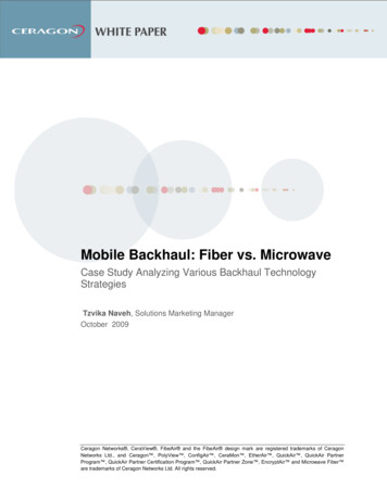
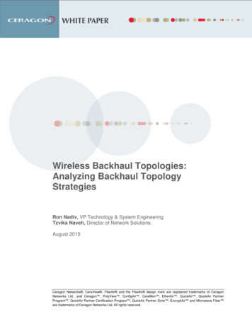
CAPEXComparing the networks’ fixed assets costs (CAPEX), we can see that the ring requires fewermicrowave links. On the other hand, rings require higher-capacity links, usually at a highercost and consuming more spectrum. The ring also requires some additional antennas,therefore the cost comparison is not straight forward, and can vary depending on theparticular case. Another factor influencing cost is spectrum reuse. Since rings have no morethan two links at every node, better frequency reuse is usually achieved and rings are oftenimplemented using only a single pair of frequency channels.ResiliencyA clear cut advantage of ring topology is its superior resiliency. The protected tree is indeedprotected against equipment failures, but does not provide any path redundancy. Thus it ismore vulnerable to heavy fade conditions, as well as to complete site failure (due to anelectricity outage, or weather-related disturbances).Consider the storm scenario shown in Figure 3. In the test case, this site is subject tocomplete failure (due to heavy rain or power failure), causing failure in four other sites in thetree, but no other sites in the ring.Figure 3: Protection Schemes in a Storm ScenarioAvailabilityThe ring also provides superior availability, due to the ring’s inherent path diversity. In a ringtopology, service failures occur only when both paths fail. Thus, in order to achieve the sameend-to-end target availability within a tree and a ring, the ring links can be designed for loweravailability than the tree links. Operators can therefore reduce expenses by deploying smallerantennas, and by reducing power at the ring link sites.WHITE PAPER Wireless Backhaul Topologies: Analyzing Backhaul Topology Strategies4
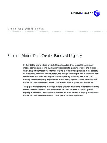
The following diagram illustrates these availability considerations. If we assume uncorrelatedfailure events (caused, say, by rain fade) for each link, and that each link is designed for 4x9savailability, then we can see in the following example that a ring yields much betteravailability. In fact, the service availability in the ring is better than 6x9s, as a service failurerequires both paths to fail, the probability of which is (1-0.9997)*(1-0.9992). While in real lifewe cannot always assume such non-correlation, it nevertheless illustrates the big difference inrobustness between ring and tree topologies.Figure 4: Tree and Ring Availability ScenariosLatencyA disadvantage of the ring topology is that it takes more radio hops to reach distant sites. Ifdesigned properly, the shortest path can be selected for each traffic flow, but in case of aprotection switch due to a cut in the ring, traffic can flow over N-1 hops in an N-node ring. Thenumber of hops can be an issue when considering latency and delay variation, adverselyaffecting the delivery of synchronization signals. Still, when considering the smaller number ofhops in the tree, one should remember that some of the tree’s links offer lower bandwidth thanthose in the ring, with negative implications for delay variation, so this drawback is subject todebate. As an alternative, the maximum number of hops can be limited using a ring-treecombination, employing several smaller rings, as shown above.Capacity & ScalabilityStatistical multiplexing is more effective and easier to implement in a ring topology, as thetotal capacity of the links in a ring is generally greater than that of the links in the branches ofa tree.WHITE PAPER Wireless Backhaul Topologies: Analyzing Backhaul Topology Strategies5
When increasing capacity, however, rings are more expensive to upgrade, as each linkrequires an identical upgrade. This is in contrast to tree topology, in which only the tree trunkneed be upgraded when adding another branch.One way to increase ring capacity without requiring an upgrade of every link, is to evolve itinto a mesh by adding crossing links, and breaking the ring into smaller rings. However, thisintroduces additional operating expenditures, due to the complexity of managing theadditional connections and protection schemes.Test Case ConclusionTo conclude, there is no single "correct" topology. Network planners should consider therelevant environmental and business conditions (such as available spectrum, and radio andantenna costs), reliability requirements, and application characteristics, in order to determinethe best solution for their needs.Tree TopologyRing TopologyCAPEX Resiliency Availability Latency Scalability Capacity Table 2: Test Case SummaryWHITE PAPER Wireless Backhaul Topologies: Analyzing Backhaul Topology Strategies6
A REAL-LIFE CASE STUDYA major Latin American mobile operator is now in the process of migrating its network fromTDM to IP – introducing new 3G (UMTS) base stations with Ethernet ports, and expanding itsMPLS network from the core to the aggregation network for packet-based backhaul. Theoperator’s backhaul strategy is to aggregate all the cellular traffic in the access network, usinghybrid TDM/Ethernet wireless microwave up to the aggregation/hub site. From theaggregation site, all the traffic is carried over a fiber optic infrastructure. Each aggregation sitecontains both SDH cross-connect facilities for TDMA, 2G and 3G voice services, and anMPLS router for the 3G HSPA Data offload, carried over a Layer-3 VPN.While planning the network migration, the operator cited three major backhaul requirementsand planning constraints: Higher bandwidth. Each cell site requires 45 Mbps of bandwidth for Ethernet traffic,with an additional 2-6 E1s for legacy TDM flows. For the Ethernet traffic, statisticalmultiplexing is employed in accordance with a selected oversubscription factor andthe number of input branches.High network availability. In order to maintain maximum availability, the operatorrequires all wireless links to be fully 1 1 protected, including tail sites – for reasonssuch as limited accessibility to many sites, high rain-rates, and the cookie-cutterapproach to site deployment of many operators.Scarce frequency resources. Over-the-air spectrum is a limited resource subject toregulatory allocation and fees.In this study, two alternative topologies for providing wireless backhaul for the access networkare proposed, both of them capable of supporting hybrid TDM and Ethernet services: 1 1 tree topologyRing topology with a local optimization schemeTable 3 below provides a line-by-line comparison of the adaptability of tree and ringtopologies to the requirements of mobile operators. Ceragon is able to support bothtopologies – without the need for external networking equipment such as TDM cross-connect(ADM/MSPP) Ethernet switches or IP routers.WHITE PAPER Wireless Backhaul Topologies: Analyzing Backhaul Topology Strategies7
Tree TopologyRing TopologyTopology# of Wireless Links20# of AntennasRemote SiteAvailability Calculation(percent of uptime)Resiliency SchemeFrequency Reuse12(1 1 protected links are counted as 2 links)2099.97% Immunity from equipment failure During site failure in a Hub-site the wholebranch is affectedNote: 5x9s target availability requires largerantennas additional cost!Equipment ProtectionMedium Reuse 3 frequenciesrequired Several links all originated at the sameHub/Aggregation site2499.9999% Immunity from site failure (e.g. powersupply), equipment failure and heavyfade conditions (e.g. bad weatherconditions)Note: 5x9s target availability can bereached using smaller antennas cost reductionRing Protection and Path DiversityHigh Reuse 2 frequenciesrequired These rings are implemented by twofrequency pairs, not more than twolinks at each site Line-of-sight was available betweenall adjacent sitesRequired ChannelBandwidthPower consumptionand occupied footprintTotal Cost ofOwnership(CAPEX & OPEX)Medium 7x 7MHz @ 128QAM 3x 28MHz @ 128QAMHigh 12x 28MHz @ 128QAM---33% less than Tree topologyEach Hub/Chain site contains between 4-6radio unitsEach site contains two radio units(East/West)--- CAPEX – 19% Less OPEX – 38% LessTable 3: Case Study ComparisonWHITE PAPER Wireless Backhaul Topologies: Analyzing Backhaul Topology Strategies8
From the case study comparison in Table 3, we can see that by maintaining a comprehensive,network-wide perspective, (rather than a link-by-link approach), and by adoption of a ringbased topology, mobile operators can reduce their Total Cost of Ownership (TCO), whileadhering to backhaul capacity requirements and planning constraints. The example abovedoes not require a complete renovation of the backhaul network in order to build a ring. Infact, it can be implemented as a local optimization either at the access backhaul or at theaggregation backhaul to achieve better TCO.Unlike the theoretical test-case presented in section 3, the real-life customer demanded thatall the links in the network be 1 1 protected. This added to the total number of links requiredin the network, and made the ring topology even more attractive. Using a Ring, the number oflinks is significantly reduced – from 20 links to only 12 (assuming 1 1 is counted as twolinks).The real-life scenario offers CAPEX reduction of 19% and OPEX reduction of 38%. CAPEXincludes microwave radio equipment and antennas, while the OPEX includes maintenancecosts, power consumption, and frequency license fees.The bandwidth capacity and high availability requirements, as well as the scarce frequencyresource constraints, are all complied with by manipulating traffic flows over the ring, usingring-inherent diverse routes as illustrated in Figure 5 below.Figure 5: Doubling Ring Capacity using Spanning Tree ProtocolResiliency DesignThe concept in the Ring topology is one of Differentiated Services – or providing differentlevels of availability to different services. Please see Figure 6 – here we show how you canguarantee high availability to real-time, revenue-generating services such as voice, whileproviding lower priority to best-effort, high-volume data applications, like web browsing oryoutube etc.WHITE PAPER Wireless Backhaul Topologies: Analyzing Backhaul Topology Strategies9
Mobile operators can reallocate redundant protection bandwidth over the ring for other uses,such as low-priority, high-volume data transfers. During this reallocation, real-time servicesare not compromised.Figure 6: Service Resiliency - Reserved & Alocated versus Reserved but not AlocatedCeragon demonstrates how a similar approach for differential services is adapted to mixedEthernet and TDM traffic modes, otherwise known as Native2 or hybrid. Real time traffic suchas native TDM (E1/DS1) is most often protected using the SNCP 1 1 method. This reservesand allocates capacity for both the primary and alternate paths, leaving very little for emergingEthernet data traffic in new 3G deployments. Ceragon's protected-ABR (Adaptive BandwidthRecovery) is based on SNCP 1:1. This enables TDM traffic to be protected by reservingbandwidth on the alternate path, but only allocating the capacity in case of a failure state onthe primary path. This extra bandwidth is made available at normal state for data applicationsand in effect almost doubles the capacity of the entire ring.WHITE PAPER Wireless Backhaul Topologies: Analyzing Backhaul Topology Strategies10
SummaryThe rapid growth in demand for bandwidth-hungry mobile data services requires operators torethink the backhaul networks that support those services. Traditionally, microwave backhaulnetworks have been based on tree topologies. However, as they rethink their backhaulnetworks, operators are finding that they can enhance quality and minimize costs byintroducing ring configurations.The shift to Ethernet transport technologies has changed the economics of the microwave ringarchitecture. Unlike with traditional TDM-based SONET/SDH rings, network operators canoptimize network resources by using statistical multiplexing and differentiated classes ofservice. This approach allows all of the cell sites on the ring to share the ring’s bandwidth,prioritizing time-sensitive traffic such as voice, and supporting bursts of lower priority trafficfrom individual sites when sufficient bandwidth is available.As the full efficiencies of Ethernet-based mobile backhaul are realized, ring architecturesbecome less costly than tree topologies, while providing higher levels of reliability. The casestudy presented in this document does not necessarily require a complete renovation of thebackhaul network, but rather is implemented as a local optimization either at the access oraggregation backhaul level in order to achieve better TCO.The purpose of this document was to provide general, high-level design concepts for planningmicrowave backhaul networks, without taking into account operator-specific network planningconstraints. Ceragon wishes to play an active role in the design and implementation ofbackhaul networks, and therefore offers service providers the opportunity to focus on serviceprovisioning and revenue enhancement, as they free themselves from the task of the networkarchitecture specialist.For more information, please visit our web site: www.ceragon.com.Ceragon’s Wireless Backhauling SolutionThe FibeAir IP-10 is Ceragon’s family of high-capacity microwave backhauling products,offering integrated Layer 2 networking capabilities. With its integrated MEF-certified CarrierEthernet Switch and integrated TDM cross-connect facility, the platform enables operators tobuild LTE-ready backhaul networks today - offering a risk-free migration all the way from 2Gto LTE, while reducing Total Cost of Ownership (TCO).Reducing CAPEXFibeAir IP-10 provides operators with an all-in-one-box networking solution - serving both asan Ethernet Switch, and as a TDM cross-connect system. By deploying the carrier-classFibeAir IP-10 at network junctions, operators can reduce or eliminate the need for standalone Layer-2 equipment such as Ethernet switches, or SONET/SDH-based ADMs – reducingcapital expenditures (see Figure 7 below). Ceragon’s Native2 hybrid solutions carry bothWHITE PAPER Wireless Backhaul Topologies: Analyzing Backhaul Topology Strategies11
TDM and Ethernet traffic over a single microwave link, saving additional CAPEX by alleviatingthe need for separate TDM and packet infrastructures.Figure 7: Cost Savings with Ceragon’s Integrated Networking FunctionalityReducing OPEXFibeAir IP-10, as a one-box, multi-service solution, reduces footprint size at the cell site,lowering rack-space leasing costs. It also reduces electricity costs, automatically suitingpower consumption in accordance with current traffic loads and environmental conditions.In addition, the FibeAir one-box approach saves on maintenance costs, requires less cabling,and reduces network down-time.The FibeAir IP-10 is managed by PolyView, Ceragon’s powerful and user-friendly networkmanagement system. Using PolyView, operators can reduce operational expenditures with itsend-to-end provisioning facility, efficient network maintenance capabilities, and fast, powerfultroubleshooting tools.CapacityThe FibeAir IP-10 family of microwave backhauling products covers the entire licensedfrequency spectrum and offers a wide capacity range, from 10Mbps to 500Mbps (full duplex)over a single radio carrier, using a single RF unit. FibeAir allows carriers to expand capacity to1 Gbps, using XPIC (Cross Polarization Interference Cancellation).WHITE PAPER Wireless Backhaul Topologies: Analyzing Backhaul Topology Strategies12
AvailabilityIn addition to its SONET/SDH protection switching capabilities, Ceragon wireless backhaulsolutions offer additional LTE-ready, Ethernet and radio traffic resiliency capabilities. TheFibeAir IP-10 platform supports ring-based protection using Rapid Spanning Tree Protocol(RSTP), assuring path protection with fast restoration, delivering service restoration within therequested range of 50ms - 250ms as specified in the Next Generation Mobile Networks(NGMN) Alliance document.ScalabilityCeragon’s FibeAir IP-10 is a unique, modular nodal solution that enables carriers to costeffectively scale their backhaul networks. Multiple FibeAir IP-10 indoor units (IDUs) can becombined in a modular way to form highly integrated and fully redundant nodal configurationswith an extended number of supported radios, TDM and Ethernet interfaces. Using thisapproach, any tail site can be seamlessly upgraded to become chain or node sites, fully reusing the installed equipment.WHITE PAPER Wireless Backhaul Topologies: Analyzing Backhaul Topology Strategies13
GlossaryABRAdaptive Bandwidth RecoveryADMAdd/Drop MultiplexerCAPEXCapital ExpendituresHSPAHigh Speed Packet AccessIDUIn-Door UnitIPInternet ProtocolL3 VPNLayer 3 Virtual Private NetworkLOSLine Of SightMPLSMulti Protocol Label SwitchingMSPPMulti-Service Provisioning PlatformOAMOperation, Administration and MaintenanceOPEXOperating ExpensesPDHPlesiochronous Digital HierarchyQoSQuality of ServiceRSTPRapid spanning tree protocolSDHSynchronous Digital HierarchySNCPSub-Network Connection ProtectionSTPSpanning Tree ProtocolTCOTotal Cost of OwnershipTDMTime Division MultiplexingXPICCross-polarization Interference CancellationWHITE PAPER Wireless Backhaul Topologies: Analyzing Backhaul Topology Strategies14
ReferencesKrzysztof Iniewski , “Convergence of Wireless, Wireline, and Photonics Next GenerationNetworks”, Chapter 6, “Point to Point Microwave Backhaul” (by Ron Nadiv). To .html)ITU-T Rec. G.8032/Y.1344, “Ethernet Ring Protection Switching,” 2008.ITU-T Rec. G.8031/Y.1342, “Ethernet Linear Protection Switching,” 2006.ABOUT CERAGONCeragon Networks Ltd. (NASDAQ: CRNT) is the premier wireless backhaulspecialist.Ceragon’s high capacity wireless backhaul solutions enable cellular operators andother wireless service providers to deliver 2G/3G and LTE/4G voice and dataservices that enable smart-phone applications such as Internet browsing, musicand video.With unmatched technology and cost innovation, Ceragon’s advanced point-topoint microwave systems allow wireless service providers to evolve theirnetworks from circuit-switched and hybrid concepts to all IP networks.Ceragon solutions are designed to support all wireless access technologies,delivering more capacity over longer distances under any given deploymentscenario.Ceragon’s solutions are deployed by more than 230 service providers of all sizes,and hundreds of private networks in more than 130 countries.Visit Ceragon at www.ceragon.comWHITE PAPER Wireless Backhaul Topologies: Analyzing Backhaul Topology Strategies15
WHITE PAPER Wireless Backhaul Topologies: Analyzing Backhaul Topology Strategies 2 Introduction . contains both SDH cross-connect facilities for TDMA, 2G and 3G voice services, and an MPLS router for the 3G HSPA Data offload, carried over a Layer-3 VPN. While planning the network migration, the operator cited three major backhaul .