Transcription
Transforming CriticalCommunicationsNetworks forSubstation AutomationCommunications network infrastructurerequirements and architecturesTechnology White PaperWith a range of compelling market drivers, power utilities are transforming theway they operate and how they deliver electricity to customers. One of the principalchanges is the technological development of substation automation to improvesmart grid performance and efficiency and to simplify substations. Substationautomation calls for extensive real-time operational information exchange and alarmstatus monitoring by deploying next-generation IP- and Ethernet-based intelligentelectronic devices (IEDs).To handle this IP and Ethernet traffic, a new communications network infrastructureis required inside the substation and in the WAN connecting the substations andcontrol center. This paper describes the requirements and outlines the architecturesand Alcatel-Lucent IP/MPLS solutions for smart grid infrastructures that enablesubstation automation, within and between substations and in the WAN. The paperalso provides information about the current Smart Substation project in France, inwhich Alcatel-Lucent is playing a key role in implementing digital smart substationsfor significant electrical grid performance improvements and cost reduction.
Table of contentsOrigins and drivers of substation automation/1Substation automation and IEDs / 1Enabling substation automation in communications networks/2IEC 61850 and communications network standardization / 2Intra-substation communications for substation automation/5Process bus traffic / 5Station bus traffic / 5Alcatel-Lucent networking solution for intra-substation communications / 10WAN communications for substation automation/12Inter-substation communications / 13Substation-to-control center communications / 13WAN communication requirements / 13Alcatel-Lucent networking solution for substation WAN communications / 16Case study: Smart Substation project in FranceParticipation of Alcatel-Lucent / 18ConclusionAcronymsReferences/1819//20/17
Origins and driversof substation automationElectric utilities are transforming the way they operate and how they deliver electricityto customers. The market is driving a range of changes: Increased power grid reliability and avoidance of blackouts Introduction of renewable energy, which causes energy generation to become distributedand irregular Emergence of electric vehicles and the associated mobility Improvement of power quality by eliminating voltage surges and brownouts Decreased transmission and distribution energy lossOne of the principal changes is the technological development of substation automationto improve grid performance and efficiency and simplify substation operation. Substationautomation calls for extensive real-time operational information exchange and alarm statusmonitoring by deploying next-generation IP- and Ethernet-based intelligent electronicdevices (IEDs). This information must be exchanged with other IEDs in the same orneighboring substations, or in control-center supervisory equipment for control, protection,wide-area situational awareness, fault and outage prevention management, and operationaloptimization of the grid.To meet these challenges and to handle new IP and Ethernet traffic, a new communicationsnetwork infrastructure is required inside the substation and in the WAN connecting thesubstations and control center. This paper identifies the requirements and outlines thearchitectures and solutions for the infrastructure that enables substation automation.Substation automation and IEDsThe substation automation initiative originated in electronics and computer technologyadvances that triggered the evolution of substation equipment from electromechanicaldevices to microprocessor-based next-generation IEDs such as digital protection relays,digital transducers, recloser controls and programmable logic controllers. These smartdigital IEDs perform traditional functions such as protection, remote monitoring and controlat a lower cost and with less physical space compared to their electromechanical precursors.To address the previously listed market-driven changes, utility companies are also deployingnew IED-based grid applications, such as wide area measurement (WAM), volt-VARoptimization (VVO), and fault detection, isolation and recovery (FDIR), also known as faultlocation, isolation and service restoration (FLISR).The next-generation IEDs are IP- and Ethernet-based. Depending on the application, IEDscan frequently transmit and receive control and data information to and from other devicesinside substations, at neighboring substations, and control-center master equipment. Forexample, digitized measurement readings carried in the Sampled Value (SV) protocol canbe above 10 Mb/s per SV source with a high sampling rate.11According to IEC/TR 61850-90-4, section 4.2.5, an SV message of typical size of 160 octets can be transmitted as frequently as every 250 µs in a50 Hz grid or 208.3 µs in a 60 Hz grid. This amounts to 10.2 Mb/s or 12.3 Mb/s respectively.Transforming Critical Communications Networks for Substation AutomationAlcatel-Lucent Technology White paper1
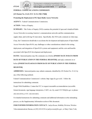
Enabling substation automationin communications networksBuilding a best-in-class communications network is indispensable when implementingsubstation automation. Today, substation equipment vendors use proprietarycommunication protocols, with a lack of interoperability. The physical partitioning ofcommunications networks causes multiple network silos, with rigid hardwiring betweendevices inside substations. In addition, fixed TDM and multiple physical circuits in theWAN form multiple networks overlaying the same physical network infrastructure.Figure 1 shows the high-level architecture of a traditional substation.Figure 1. Traditional substation onalsubstationMultiple MUXsIEDsCHardwiringBAIEC 61850 and communications network standardizationCapitalizing on the evolution of substation automation and the trend toward openinteroperability in the communications industry, IEC Technical Committee 57 hasstandardized the substation automation communications network in IEC 61850. The IEC61850 suite defines both the communications network architecture and communicationprotocols. With the adoption of IEC 61850, power utilities can benefit from: Interoperability among substation equipment vendors, enabling multivendor applicationenvironments Deployment of cost-effective, fiber-based optical Ethernet LANs instead of hardwiringat the process level, for significant material and installation cost savings Consolidation of multiple network overlays into one converged next-generationcommunications networkTransforming Critical Communications Networks for Substation AutomationAlcatel-Lucent Technology White paper2
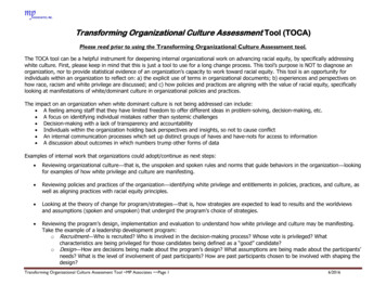
IEC 61850 identifies two types of traffic flow in communications networks, as shown inFigure 2: Flow type 1 (Figure 2, 1a to 1e) for traffic flow within the substation (intra-substation) Flow type 2 (Figure 2, 2a and 2b) for traffic flow outside the substation over the WANto another substation (inter-substation) or to the control centerThe next sections provide descriptions of these traffic types.Figure 2. IEC 61850 communications network architectureRemote accessControl centerOperations WAN2b2aStation levelSubstation AGatewaySubstation BHMI1e1dBay levelStation bus1bBay controlProcess busProtection1a1cBay controlProcess busProcess levelProcess levelProcess levelPrimary equipment withdigital sensor and merging unitProcessProcess levelPrimary equipment withdigital sensor and merging unitProcessTransforming Critical Communications Networks for Substation AutomationAlcatel-Lucent Technology White paper3ProtectionBay controlProtection
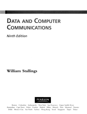
IEC 61850 defines two types of protocol stack, as shown in Figure 3: Hard real-time stack: Contains delay-sensitive traffic and requires real-time processingby such applications as SV, carrying digitized current and voltage measurements andGeneric Object Oriented Substation Events (GOOSE) for teleprotection.To speed application processing, the communication protocol stack is reduced to theminimum of Ethernet only. Soft real-time stack: Contains traffic that requires reliable delivery but is not asdelay-sensitive.Examples of traffic types are Manufacturing Message Specification (MMS)-basedapplications such as supervisory control and data acquisition (SCADA) with DistributedNetwork Protocol version 3 (DNP3) or IEC 60870-5-104 and WAM/synchrophasor.Figure 3. IEC 61850 protocol stackHard real-time stackSoft real-time stackPublisher-subscriber servicesClient-server servicesSampledvaluesGOOSEIEEE 1588MMS(e.g., SCADA)SNTPUDPTCP/UDPIP802.1QPT 88-B8PT 88-F7PT 08-00802.1Q802.1Q802.1Q(optional)VLAN and priority 802.1P (optional)Link redundancy entity (IEC 62439-3 PRP/HSR PT 00-FB)Ethernet BEthernet ATransforming Critical Communications Networks for Substation AutomationAlcatel-Lucent Technology White paper4
Intra-substation communicationsfor substation automationEarly substation architecture adopted a centralized concept because of limited processorpower and communications technology. Defined in IEC 61850, the new processorempowered IED-based architecture is distributed in three levels inside a substation,as shown in Figure 2: Process level: Bottom level, for instrumental transformers and switch equipment Bay level: Middle level, for the bay controller and IEDs for metering, disturbancerecorder and protection Station level: Top level, for station computers and controlA process bus operates between the process and bay levels, and a station bus operatesbetween the bay and station levels. “Bus” is a standard term for a broadcast domain, suchas a LAN. The process bus and station bus enable communications among the three levelsas shown in Figure 2, flow 1a to 1e.Process bus trafficThe process bus connects plant equipment (intelligent switch equipment as well as currentand voltage transformers) and IEDs. The traffic is typified by flow 1a for communicationbetween plant equipment IEDs and mainly comprises SV, GOOSE and MMS protocolmessages. The process bus must provide guaranteed Quality of Service (QoS) for real-timeSV and GOOSE traffic and reliable delivery for MMS traffic.Station bus trafficThe station bus interconnects the entire substation and provides connectivity betweencentral management and the individual bays. The station bus also connects the deviceswithin a bay and between different bays. This traffic is typified by: Flow 1b for data exchange within the bay level Flow 1c for direct data exchange between bays, especially for fast functions such asinterlocking Flow 1d for the exchange of protection data and control data between the bay and stationlevels Flow 1e for data exchange within the station level, such as between the SCADA gatewayand its human-machine interface (HMI) computerThe traffic is mainly GOOSE, MMS, Simple Network Management Protocol (SNMP)and File Transfer Protocol (FTP) messages as well as video and Voice over IP (VoIP).SV messages are also sometimes used in busbar protection applications.Intra-substation communication requirementsIntra-substation communications involve a range of network requirements: Network virtualization Redundancy protection Advanced traffic management Operations, administration and maintenance (OAM) performance and fault management Security SynchronizationTransforming Critical Communications Networks for Substation AutomationAlcatel-Lucent Technology White paper5
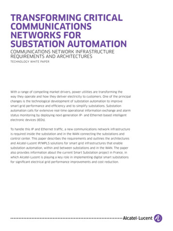
Network virtualizationAs previously described, traffic generated by multiple applications — for example,teleprotection, SCADA and SV — is carried over the substation communicationsinfrastructure. To support a multiservice architecture, network virtualization with virtualLAN (VLAN) bridging is required to isolate each application. Each virtual bridge must haveits own Media Access Control (MAC) forwarding table to process the traffic, QoS policy,and bandwidth partitions. There are two Ethernet networking options: Virtual Private LANService (VPLS) over Multiprotocol Label Switching (MPLS) ring or VLAN ring.VPLS over MPLS ringA VPLS creates a virtualized LAN connected by a pseudowire that runs over an MPLStunnel between nodes. A VPLS is fully capable of learning and forwarding on EthernetMAC addresses and is interoperable with E-LAN switches. Connected by a pseudowire overMPLS (see Figure 4), a VPLS can capitalize on MPLS in SDH/SONET-like ring recovery anda full OAM suite. Moreover, the same MPLS technology in the substation network and inthe WAN enables synergy, with a common network design methodology and operationprocedure design. The use of MPLS in the WAN is discussed later in this paper.Figure 4. VPLS over MPLS ringBay level controlsProtection relayPseudowireMPLS-enabledEthernetswitchVPLS overMPLS ringProcess unitProcess unitSwitchyarddeviceTransforming Critical Communications Networks for Substation AutomationAlcatel-Lucent Technology White paper6InstrumentaltransformersSwitchyarddevice
VLAN ringVLAN bridging is used to virtualize the Ethernet ring by connecting the Ethernet switcheswith the VLAN trunk in the ring (see Figure 5). ITU-T G.8032 or Rapid Spanning TreeProtocol (RSTP) can be used to prevent loop formation in the ring.Figure 5. VLAN ringBay level controlsProtection relayVLANEthernetswitchVLANringProcess unitProcess unitSwitchyarddeviceInstrumentaltransformers Redundancy protectionRedundancy protection is essential when carrying critical industrial applications. As shownin Figure 6, a ring topology is optimal for providing network redundancy. In case of a linkfailure in the network, RSTP or Ethernet Ring Protection Switching (ITU-T G.8032) can beused for network recovery. Because ITU-T G.8032 uses ITU-T Y.1731 OAM for quick faultdetection and is optimized for ring protection, it can provide SDH/SONET-like speed forswitching protection.However, the Ethernet links between process units and the Ethernet switch remain a point offailure. In addition, the SV protocol requires seamless redundancy protection with zero failovertime, which goes beyond what a communications network can support. IEC 61850 thereforestandardizes application-level protection schemes that ride transparently over the E-LAN:Parallel Redundancy Protocol (PRP) and High-availability Seamless Redundancy (HSR).Transforming Critical Communications Networks for Substation AutomationAlcatel-Lucent Technology White paper7Switchyarddevice
Figure 6. Ethernet ring in substation busBay level controlsProtection relayEthernetswitchRSTP orG.8032 ringProcess unitProcess yarddeviceThe PRP end device has two links that connect to two parallel LANs of any topology,including ring and star. Figure 7 shows a reference ring architecture. The process bustransmits and receives duplicated traffic in both networks and can filter on only one flow.In case of an end-link failure or multiple failures in the LAN, communications can continueusing the second link and second ring without traffic loss.Figure 7. Process bus with PRPBay level controlsProtection relayProtectionringProcess unitProcess unitSwitchyarddeviceTransforming Critical Communications Networks for Substation AutomationAlcatel-Lucent Technology White paper8InstrumentaltransformersSwitchyarddevice
At the station bus, unless SV messages are also carried, a meshed or ring architecture canusually be used to provide redundancy, as shown in Figure 8.Figure 8. Station bus architectureStation busWi-FiHMICCTVMeteringBay level controlsProtection relayProtectionringProcess unitProcess unitSwitchyarddeviceInstrumentaltransformersHSR is another application-level scheme that works transparently with existing LANs.However, the underlying LAN is restricted to a ring architecture. Advanced traffic managementBecause some applications are delay-sensitive and operate in real time, the network must beable to deliver this traffic with complete reliability. The network platform must, on a per-VLANbasis, perform hardware-based switching with low latency and advanced traffic classification,using a high-priority forwarding class without sacrificing forwarding performance.Traffic queuing and scheduling on a per-application, per-class basis enable the appropriatesharing of Ethernet link bandwidth while managing application delivery. Combining trafficqueuing and scheduling with hierarchical traffic rate limiting or shaping guarantees theproper bandwidth amount and priority for each application to run seamlessly. OAM performance and fault managementDelay is critical for some traffic flows, so it is important that network performancemeasurement — for example, delay, jitter and packet loss — can be continually verified atall substations. When the measurement threshold is reached or exceeded, a comprehensivesuite of OAM tools should be available for troubleshooting at different locations for differentlayers. The OAM measurements can be orchestrated from the management platform using alightweight portal that can also generate statistics reports.Transforming Critical Communications Networks for Substation AutomationAlcatel-Lucent Technology White paper9Switchyarddevice
SecurityAs critical infrastructure, substation equipment must have strong protection. In NorthAmerica, the Federal Energy Regulatory Commission (FERC) has adopted CriticalInfrastructure Protection (CIP) Version 5, authored by the North American ElectricReliability Corporation (NERC), as the mandatory guidelines for power utilities to follow.Internationally, the IEC 62351 and ITU-T X.805 standards are the key recommendations.Within the sheltered substation environment, security protection with authentication foraccess to the Ethernet switch is necessary for preventing unauthorized access, using amechanism such as Terminal Access Concentrator Access Control Server Plus (TACACS )or Remote Authentication Dial-In User Service (RADIUS). The Ethernet switch must alsosupport mechanisms such as syslog and user activity accounting for security audits.Moreover, all Ethernet ports should be disabled by default to provide port security andto support IEEE 802.1X authentication. To detect physical intrusions, dry contacts on theEthernet platform can be used to relay alarms from local facility surveillance systems. SynchronizationTime-of-day synchronization is becoming a critical requirement with the introduction ofnew applications — for example, SV and IED devices such as merging units. This type ofIED can obtain synchronization using IEEE 1588v2 distribution of time-of-day informationin addition to Inter-Range Instrumentation Group Format B (IRIG-B) interface. IRIG-B signalis carried in separate wiring and is more popularly supported today. However, the networkmust be built with IEEE 1588 readiness for future evolution.Alcatel-Lucent networking solution for intra-substation communicationsThe Alcatel-Lucent 7210 Service Access Switch (SAS)-based Ethernet networkingsolution inside substations can help network operators to build a network that fulfills therequirements listed in Table 1.Table 1. Fulfilling substation LAN communication requirements with the Alcatel-Lucent Ethernet solutionSubstation LAN requirementAlcatel-Lucent substation Ethernet networking solution featuresRedundancy protection Application layer: PRP/HSR in IED Ethernet layer: MPLS FRR, ITU-T G.8032, RSTP, LAGNetwork virtualization VPLS or VLAN bridgingQoS Flexible and advanced hierarchical queuing and scheduling VID, IEEE 802.1P, IP 5-tuples classificationOAM performanceand fault management On-node service assurance agent directed by network managerwith report generationSecurity Strong authentication capability Comprehensive syslog and user accounting for audit trail IEEE 802.1X port authentication Ethernet port down by defaultTogether with the service-aware Alcatel-Lucent 5620 Service Aware Manager (SAM) andAlcatel-Lucent Service Portal Express for Utilities, this solution brings a range of benefitsto power utilities, including rapid provisioning and work order processing, scalableperformance management, and report generation. Figure 9 shows the solution components.Transforming Critical Communications Networks for Substation AutomationAlcatel-Lucent Technology White paper10
Figure 9. Alcatel-Lucent intra-substation communications solution7210 SAS-M5620 SAMService Portal Express7210 SAS-TTable 2 lists the Alcatel-Lucent solution highlights. For more information,see ical-wide-area-network.Table 2. Alcatel-Lucent intra-substation communications solution7210 SAS5620 SAMService Portal Express for UtilitiesFlexible substation-grade Ethernetaccess and aggregation platformEnd-to-end service-awaremanagement platformAgile web-based portal for utilities 10GE link support and up to 124 Gb/shalf-duplex capacity Rapid provisioning Wider accessibility for top-levelviewsand comprehensive reportgeneration Optical integration with DWDMand CWDM PoE/PoE capable SLA monitoring with serviceassurance Correlated multilayertroubleshooting Simplified OSS integrationTransforming Critical Communications Networks for Substation AutomationAlcatel-Lucent Technology White paper11 Automated controlled workorder processing Proactive network andapplication assurance
WAN communicationsfor substation automationAs previously described, traffic that travels out of a substation into the WAN is destinedfor another substation or control center. The traffic originates from devices at the process,bay or station level, then exits the substation through a WAN gateway router, as shown inFigure 10.Figure 10. Substation with WAN gateway routerIP/MPLS network(WAN)Primary WANStation busWAN gateway routerWi-FiHMICCTVMeteringBay level controlsProtection relayProtectionringProcess unitProcess unitSwitchyarddeviceInstrumentaltransformersThe WAN gateway functions as a demarcation point between the WAN and the intrastation LAN domains and also as an entry point to all circuits and services in the WAN forcommunications traffic.Transforming Critical Communications Networks for Substation AutomationAlcatel-Lucent Technology White paper12Switchyarddevice
Inter-substation communicationsInter-substation communications serve two main functions, as shown in Figure 2, flow 2a: Protection, including distance, differential and phase comparison protection Control, such as interlockingInter-substation traffic has the following characteristics: Delay-sensitive messages encoded directly in the Ethernet payload to minimize processingdelays by end devices, as shown in the real-time stack in Figure 3 Point-to-point between IEDs in two substations Evolution to any-to-any nature for future zone-based protection and control applicationsTDM-based control and protection traffic from legacy devices will continue to be in usefor the next five to ten years. Today, this traffic is typically carried over a TDM/SONETnetwork or even dark fiber.Substation-to-control center communicationsSubstation-to-control center communications (Figure 2, flow 2b) enable control centerstaff to monitor and control the grid at a regional or national level. These types ofcommunications serve a wide range of applications, including: SCADA Synchrophasor Other dispatching applicationsIn addition to the above operational functions are non-operational applications, such asVoIP, Internet access and video surveillance.Substation-to-control center traffic has the following characteristics: Non-delay-sensitive and encoded over Transmission Control Protocol (TCP)/UserDatagram Protocol (UDP) over IP, as in the soft real-time stack in Figure 3 Point-to-point and multipoint-to-point with traffic that is merged by routing towarda central device Delay- and jitter-sensitive traffic from VoIP and video applicationsAs with inter-substation communications, TDM-based control and protection trafficfrom legacy devices is expect.ed to be in use for the next five to ten years, carried overa TDM/SONET networkWAN communication requirementsWAN communications involve a range of network requirements: Network topology and medium versatility Network virtualization and service flexibility Redundancy protection Traffic engineering Advanced traffic management OAM performance and fault management Security SynchronizationTransforming Critical Communications Networks for Substation AutomationAlcatel-Lucent Technology White paper13
Network topology and medium versatilityWhile it is feasible to choose and build a topology with the optimal choice of fiber insidea substation, this is not always possible in the WAN. Power utilities must be resourceful,making use of whatever network assets are available, including microwave. Where fiber isavailable, Coarse Wavelength Division Multiplexing (CWDM) technology can be integratedin the network for future traffic growth. Where fiber is not available, an attractive optionis next-generation packet microwave, which supports higher transmit power, MPLS-awarepacket compression, and advanced microwave link types such as Cross PolarizationInterference Cancellation (XPIC).The WAN circuit or tunnel between any two locations must be built seamlessly and scalablyend-to-end, independent of the network topology and network medium in between. TheWAN gateway router, which integrates the microwave and CWDM add/drop multiplexerfunctions, can consolidate multiple layers of different transmission media to streamline theWAN design and operation. Network virtualization and service flexibilityAs previously described, WAN traffic has diverse characteristics: it can ride over Ethernetor IP in real time or non-real time in a point-to-point or multipoint pattern, connecting toneighboring substations or to a control center. Point-to-point and multipoint bridging TDMtraffic from current applications must still be transported in the future.Table 3 lists some major applications and WAN traffic characteristics.Table 3. WAN traffic characteristics and service typesApplicationInterfaceServiceTeleprotectionTDM (serial, E&M, ITU-T G.703),EthernetTDM circuit emulation,EthernetTelecontrol/SCADATDM (serial), IPoETDM circuit emulation/databridging, P routing or Ethernet VLLIED managementIPoEIP/EthernetThe communications network must be virtualized to support each application with thecorrect type of virtual private network (VPN). Redundancy protectionHigh availability in the WAN is critical for reliable grid operation. The WAN must be ableto recover at SDH/SONET speed in case of a network failure. In addition, the WAN mustsupport physical-site diversity protection for the control center. In the case of primarycontrol center damage, the substation WAN gateway router automatically switches to thestandby control center, which could be far away. This kind of control-site redundancysupport is essential for ensuring the continued operation of the grid in case of disaster. Traffic engineeringWith a network topology such as ring or meshed, traffic engineering must be able toachieve network bandwidth and resource optimization, particularly when microwave linksare in use. This capability helps operators to direct traffic depending on different criteria,including application type and class of service.Transforming Critical Communications Networks for Substation AutomationAlcatel-Lucent Technology White paper14
Advanced traffic managementThe network must be able to classify and prioritize a diverse mix of traffic according toits forwarding class so that high-priority TDM and real-time traffic is sent with the highestpriority while the rest of the traffic is sent reliably across the network. OAM performance and fault managementBecause delay is critical for some traffic flows, network performance — for example,delay, jitter and packet loss — must be continually verified at a wide network scale.When problems occur, a comprehensive suite of OAM tools should be available fortroubleshooting different layers.Performing these kinds of tasks using a traditional command-line interface is tediousand error-prone. A preferred approach is to automate tasks using a network managerso that measurement is scalable and efficient. SecurityAs critical infrastructure, the power grid must have strong protection. The WAN routerin the network core as well as at the edge (the WAN gateway inside the substation) mustprovide fortified security protection to the network and to the substation equipment,playing the role of an electronic security perimeter in the routing, signaling and data planes.In North America, NERC CIP Version 5 has been adopted by the FERC as mandatory forpower utilities. Internationally, the IEC 62351 and ITU-T X.805 standards are the keyrecommendations.Comprehensive protection must occur at both the network infrastructure and service layersin all routing, signaling and data plane dimensions. Moreover, to relay alarms to the controlcenter, the platform can provide dry contacts that connect to a local facility surveillancesystem. SynchronizationSynchronization is critical for ensuring that applications run smoothly. Legacy TDMbased applications such as teleprotection and SCADA require end-to-end frequencysynchronization. Depending on the network topology and transmission medium, thereare different frequency synchronization options. For example, line synchronization fromSynchronous Ethernet, microwave link and SDH/SONET links is ideal for transportingfrequency synchronization.When line synchronization is not feasible, IEEE 1588v2 delivery over the WAN is possibleif the network elements can provide IEEE 1588v2 hardware assist in the form of a boundaryclock or transparent clock. The WAN gateway router, as an IEEE 1588v2 s
MPLS (see Figure 4), a VPLS can capitalize on MPLS in SDH/SONET-like ring recovery and a full OAM suite. Moreover, the same MPLS technology in the substation network and in the WAN enables synergy, with a common network design methodology and operation procedure design. The use of MPLS in the WAN is discussed later in this paper. Figure 4.