Transcription
The Future of Gas Turbine Technology8th International Gas Turbine Conference12-13 October 2016, Brussels, BelgiumPaper ID Number (07-IGTC16)STARTUP TIME REDUCTION FOR COMBINED CYCLE POWER PLANTSPascal Decoussemaeker, Anand Nagasayanam / GE PowerBrown Boveri Strasse 7, 5400 Baden, Switzerland 41 58 505 96 37, pascal.decoussemaeker@ge.comWesley P. Bauver / GE Power175 Addison Road, Windsor, CT, USA 1 860 285 4238, wesley.bauver@ge.comLuca Rigoni, Luca Cinquegrani, Glauco Epis, Marco-Ernesto Donghi / GE PowerViale Tommaso Edison 50, 20099 Sesto San Giovanni Milano, Italy 39 02243482186, luca.rigoni@ge.comABSTRACTCombined cycle power plants (CCPP’s) are highlyefficient and have a high flexibility for fast load changes.Grid operators that have to deal with changing marketconditions are therefore often using these plants tocompensate for the volatility that has been introduced intothe system by renewable energy sources. A particularscenario that is becoming increasingly popular is the use ofCombined Cycle plants to provide non-spinning capacityreserves.In order to provide non-spinning reserve, a fast andflexible startup is important. Depending on therequirements and the particular plant design, there aredifferent options to reduce the startup time. This paper willstart with an overview of the bottlenecks related to startuptime reduction and will then provide an overview of thedifferent ways around these bottlenecks. Finally, a fewcase studies will be presented of existing plants whereupgrades were implemented to reduce the startup time.INTRODUCTIONCombined cycle power plant technology is ideallysuited to support a number of different operating scenarios.In Europe, we have seen them evolving from highefficiency base load operation to a cyclic operation modeto compensate for the volatility introduced into the grid byrenewable energy sources like wind and solar. Fast back uppower can be provided in different ways. One commonlyused method is to run some of the plants on low load,ready to ramp up in case it is needed (Decoussemaeker,2015). However, with an increased portion of electricitycoming from solar and wind power plants, this wouldrequire a high number of plants to run in this less efficientoperation mode for long periods of time. Since this iscostly, and also leads to an increased specific CO2emission, the preferred way to provide backup power isnot to run on part load, but to shut down the combinedcycle plant capacity that is not needed and keep themstand-by and ready to load when their support is required.This leads to power plants that operate only a fewthousand hours per year. When a plant is shut down, it isoften not known when a restart will be required. However,when it is needed, it is important to be able to provide loadon short notice, within 30 minutes to 2 hours, dependingon the local market set-up. This leads to a number ofchallenges for the operators of these plants, such as how topreserve the components during these long periods ofinactivity and how to fast load a plant that has beenpreserved and shut down for some time. In addition, theasset condition management strategy needs to be modifiedbased on a different set of failure modes.This paper will deal with the challenge of fast andflexible starts after longer standstill periods. A total plantapproach is used to design solutions, considering theinteractions between various critical components in theplant. Changes are made to GT, HRSG, WSC and ST inorder to achieve a faster and flexible start. A previous ETN1
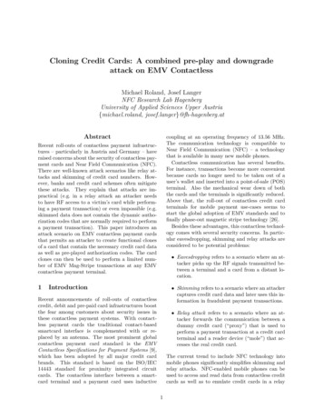
paper has dealt with the review of the asset managementstrategy for cyclic operation (Decoussemaeker et al, 2014).NOMENCLATUREBOPBalance of plantDPTDifferential pressure transmitterGTGas turbineHRHHot reheatHRSGHeat recovery steam generatorNDTNon-destructive testingNFPANational fire protection associationPEDPressure equipment directivePTPressure transmitterSEVSequential combustion chamberSTSteam turbineWSCWater Steam CycleSEVSequential Environmental BurnerOVERVIEW OF THE STARTUP SEQUENCEBefore identifying how to optimize the startup time ofthe combined cycle power plant, it is important tounderstand the different phases of the startup. The detailsof the startup sequence will differ from plant to plant. Theexample in this paper is based on a typical sequence of theGeneral Electric GT26 (See Figure 1).Figure 1: Typical cold start sequenceThe above figure depicts a typical cold start. Duringthe first phase, the gas turbine (GT) is started andsynchronized. Before the GT can start, all systems on theplant need to be ready to go. This means all auxiliary andBOP systems need to be operational and the HRSG drumlevels need to be on startup level. The GT sequencer thengoes through a purge sequence, ignition, run up to idle,synchronization and loading to minimum load. Onceminimum load is reached, the next phase can only bereleased when sufficient vacuum is built up in thecondenser to release the steam by-pass system. Thisrequires gland steam and motive steam to draw vacuumwith the startup ejector. Typically, once the pressure isbelow 300 mbar, the intermediate pressure steam by-passsystem can be released.After the start of the GT in phase 1, the steam turbine(ST) startup is the focus in phase 2. At the start of phase 2,the GT is loaded to a load that is low enough to start theST. For the GT26, this is just below the SEV switch on.The ST run up typically requires live and reheat steamtemperatures at 400 C. It is also necessary to wait until thesteam temperature, pressure and quality are within therequired limits. Once this is achieved, the ST run up isinitiated. Typically there is a ST warm up stop during therun up to manage the ST stress levels. The next phase isreleased when the ST is sufficiently warmed up and thesteam temperature can be controlled for an unlimitedloading.In the 3rd and last phase, the GT and ST are loadedbased on the gradients defined during the design of the GT,ST and HRSG.Figure 2: Typical duration of the times for thedifferent phasesFigure 2 gives an indication of typical time (inminutes) required for the different phases of the startup.This table shows that the depending on the expected typeof start (cold, warm or hot), the main focus of the startuptime reduction effort, for a particular installation, may beon a different phase of the startup. Through pre-heating orby keeping the unit warm, it is also possible to move fromone category into another. The following chapters willprovide additional detail on how to reduce the duration ofeach of the 3 phases.PHASE 1: GT STARTUPIn phase 1, the GT is started, synchronized andbrought in a stable situation with a minimum load. Thereare different ways to reduce the length of this first phase:- Reduce the time to the GT start release;- Purge credit;- Improvement of the condenser evacuation.A time consuming activity is the adjustment of theHRSG drum levels prior to startup. Preserving the HRSGwith water in the drums can save a lot of time. This can beachieved with either nitrogen blanketing or by keeping theHRSG warm. Warm keeping can be achieved with a stackdamper for shorter periods, like a weekend, and withsparging steam for longer periods. Keeping warm does notonly help in this phase, but also reduces the time requiredfor phase 2 and phase 3. For more details, see section onpreservation further in this paper.Another option to reduce the startup time is to releasethe first part of the GT or plant startup sequencer alreadybefore the water steam cycle startup release is available.2
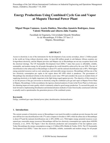
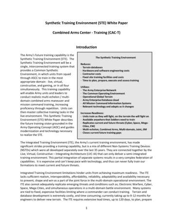
PHASE 2: COMBINED CYCLE STARTUPOnce the steam by-pass is in operation, it becomespossible to further increase the GT load and producesufficient steam to start and synchronize the ST, but nottoo much in order to limit the inlet steam temperature.There are different ways to reduce the length of this secondphase:- Reduce waiting time for the steam quality;- Pre-warming of the ST;- Optimization of the plant startup concept;- Startup the GT without waiting for the ST.Figure 3: Purge creditPart of phase 1 is also the HRSG purge by means of aGT motor roll in order to make sure that there are nocombustible gasses left in the HRSG. The NFPA85guideline is usually used as the standard for this purgecycle. The standard requires a purge volume of at least fivetimes the HRSG volume and a purge time of not less than5 minutes. This does not only require the additional timeneeded to perform the purge, but it will also require alonger heat-up time later in the startup cycle to compensatefor the energy lost because of the cool down during thepurge cycle. In addition, it requires also auxiliary power toroll the GT and may also lead to premature ageing causedby condensate flooding of the lower headers(Decoussemaeker et al, 2014). In the 2011 revision of theNFPA85 guideline, it was recognized that a normal GTshutdown does not result in a hazardous atmosphere.Therefore, a GT purge is not required for the subsequentstartup, provided that the purge condition can bemaintained. For gaseous fuels, this can be achieved bymeans of a triple block and bleed of the fuel supply, with apressurized section. As long as the positive pressure can bemaintained, the purge credit remains valid (see Figure 3).This will reduce phase 1 of the startup by 5 to 10 minutesPhase 1 ends after the synchronization of the GT andGT loading to minimum load, when a stable condition isachieved. This is the case when the steam by-pass systemhas taken over the pressure control of the HRSG. In orderto start the steam by-pass operation, vacuum in thecondenser is required. Condenser vacuum requires steamto operate the air ejectors and the ST gland steam system.If an auxiliary steam source is available, condenservacuum can be drawn ahead of time.Figure 4: HP boiler steam cation conductivity ( S duringstartup of ST (black ( ) measured, red ( ) calculatedwithout CO2, Green ( ) MW), blue ( ) calculatedfor all anions)Especially for a cold start, a large part of the waitingtime in phase 1 is the time required to achieve the rightboiler water and steam quality. Clean steam is importantfor the lifetime integrity of the ST. But also the feedwaterneeds to be clean, since it will be injected into the steamthrough the desuperheater. The cleanliness of the steam isexpressed by the conductivity. In case the cycle has beende-pressurized, CO2 will have entered the system with theair and this will lead to higher conductivity values. It willrequire some time until all CO2 is purged from the system(see Figure 4). The removal rate depends on the efficiencyof the deaeration devices (deaerator and condenser). Cyclicunits with frequent cold starts require a significantproportion of the operating time to reach normal values.This time can be reduced by installing a degassedconductivity measurement. Such an instrument willmeasure the conductivity of the sample after removal ofthe CO2. There are two widely used techniques fordegassing: gas stripping with nitrogen and heating up tonear boiling point.Another steam quality related issue is the length of thesample lines from the sampling point to the instrument. Ittakes time for the sample to reach the instrument,especially during the startup phase, when the pressure islower. This can be improved by installing a back pressure3
regulation valve to maintain sampling line pressure atlower water/steam system pressures. Further improvementcan be achieved by installing a remotely controlled purgevalve (Sigrist, 2014).However, in case it is possible to keep the air out bymeans of keeping the unit warm or using a nitrogenblanket, there will be no ingress of CO2 that will increasethe conductivity and also there will be less iron oxidesfrom corrosion during the standstill period.It is also important to have a closer look at the start-upsequencer and optimize hold points, controllers for thesteam by-pass system. Also it is important to ensure thatactivities that can be done in parallel are not executedsequentially. Examples include optimization of the STsequencer, pre-warming of the steam piping, automation ofmanual drives For a cold start, the longest waiting time is related tothe warming up of the ST in order to avoid excessivestress. If the ST can be pre-warmed, this time can beshortened. This can be achieved by injecting hot air intothe ST (see Figure 5), either in an open loop or in a closedloop.Figure 5: ST pre-warmingIf a plant is restarted to provide backup power tosupport the grid in case of sudden power shortages, it isimportant to be able to bring as much as possible power tothe grid in the shortest time. In this situation, fuelefficiency is of secondary importance. If this is the case, apossible scenario is to load the GT as much as possible,without waiting for the ST. However, if the ST is added ata later stage, the steam temperature will have to bereduced. This can be achieved by adjusting the GT inletguide vanes. If however this is insufficient, it might benecessary to add desuperheater capacity, either by addingan interstage, or an end-stage desuperheater or byupgrading the existing installation. The interstagedesuperheater capacity may be insufficient because ofinsufficient thermal head. Once the steam temperaturereaches the saturation temperature, additional water will nolonger evaporate. This condition is called overspray. Toprevent overspray, the remaining superheat downstream ofthe water injection should not drop below 28 C (50 F). Itis further important to make sure that when the amount ofwater is increased, there is sufficient downstream pipelength to ensure a complete evaporation of the waterbefore the first bend in the steam piping. To reduce therisks related to overspray or incomplete evaporation, it isrecommended to install skin thermocouples on the top andbottom of the steam piping downstream of thedesuperheater to monitor for any water accumulation.Another method to uncouple the GT loading from theST loading is by cooling through injecti
with the startup ejector. Typically, once the pressure is below 300 mbar, the intermediate pressure steam by-pass system can be released. After the start of the GT in phase 1, the steam turbine (ST) startup is the focus in phase 2. At the start of phase 2, the GT is loaded to a load that is low enough to start the ST. For the GT26, this is just below the SEV switch on.