Transcription
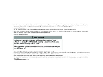
Customer Order Number: DOC-VOICEOIP-QSG Text Part Number: 78-4936-01Voice over IP Quick Start GuideProduct Numbers: NM-1V , NM-2V VIC-2E/M , VIC-2FXO , VIC-2FXS The voice over IP feature enables Cisco 3600 series modular routers to carry voice traffic, such astelephone calls and faxes, over an IP network, simultaneously with data traffic. (See Figure 1.)Figure 1Voice and Data Traffic on an IP Network10690IP cloudThis guide explains briefly how to install voice hardware and how to set up basic configurations ofCisco IOS software for a voice over IP network. It contains the following sections: What You Should Know, page 3—Describes what you should know before starting, what youshould do before configuring your voice network, conventions used in this guide, and how to findmore information. Installing Voice Network Modules and Voice Interface Cards, page 4—Describes voicehardware and explains how to install and connect it. Voice Port Numbering, page 8—Explains the interface numbering convention for voice ports.Entering Configuration Mode, page 10—Offers hints for using Cisco IOS software toconfigure a voice over IP network.Corporate HeadquartersCisco Systems, Inc.170 West Tasman DriveSan Jose, CA 95134-1706USACopyright 1998Cisco Systems, Inc.All rights reserved.1
Configuring the IP Network for Real-Time Voice Traffic, page 12—Describes how toconfigure the IP network to accommodate voice traffic. Configuring FXS Interfaces, page 16—Describes how to configure FXS voice interface cardsfor connecting a router to telephones, fax machines, and similar devices. This section alsointroduces the concepts of dial peers, which link voice ports or IP addresses with telephonenumbers, and number expansion, a shortcut to entering repeated voice-configuration commands. Configuring FXO Interfaces, page 24—Describes how to configure FXO voice interface cardsfor connecting a router to a telephone company central office. Configuring E&M Interfaces, page 26—Describes how to configure E&M voice interfacecards for connections between PBXs. Saving the Configuration, page 29—Explains how to save the configuration so it is availablethe next time you boot the router. List of Terms, page 30—Provides a list of terms and abbreviations used in this guide.Cisco Connection Online, page 32—Explains how to get service and support.2 Voice over IP Quick Start Guide
What You Should KnowWhat You Should KnowThis guide is intended for data communications managers or telecommunications managers who areinstalling, configuring, or maintaining voice network modules and interface cards. It assumes thatyou already have a working IP LAN or WAN, or that you know how to set one up, and that you wantto add voice capability to it. It does not tell you how to design or install a LAN or WAN, assign IPaddresses, install routers and configure them for IP traffic, or perform other basic tasks. It alsoassumes that you are familiar with Cisco IOS software, and that you know how to configure therouters on your LAN or WAN for IP service.For E&M installations, you should also be familiar with telephony concepts and PBX operation.The “List of Terms” near the end of this guide provides a glossary of many terms and concepts usedby voice over IP. For further information on voice over IP features, refer to the VoiceNetwork Module and Voice Interface Card Configuration Note, the Voice over IP SoftwareConfiguration Guide, your router installation and configuration guide, the Regulatory Complianceand Safety Information document for your router, and the Cisco IOS configuration guides andcommand references.Document ConventionsIn this guide: Commands in the text are shown in boldface.Variables for which you supply values are in italics.Italics are also used for the titles of publications and for new words or concepts.Information the router displays on the console screen is in screenfont.Information that you enter at the console keyboard is in boldfacescreen font.To Learn MoreCisco documentation and additional literature are available in a CD-ROM package, which ships withyour product. The Documentation CD-ROM, a member of the Cisco Connection Family, is updatedmonthly. Therefore, it might be more up to date than printed documentation. To order additionalcopies of the Documentation CD-ROM, contact your local sales representative or call customerservice. The CD-ROM package is available as a single package or as an annual subscription.You can also read Cisco documentation on the World Wide Web at http://www.cisco.com,http://www-china.cisco.com, or http://www-europe.cisco.com. From here, you can submitcomments electronically. Click Feedback on the title bar, and then select Documentation. After youcomplete the form, click Submit to send it to Cisco. We appreciate your comments.If you have questions or need help, refer to the section “Cisco Connection Online” at the end of thisguide for further information.Voice over IP Quick Start Guide3
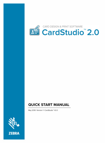
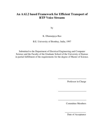
Installing Voice Network Modules and Voice Interface CardsInstalling Voice Network Modules and Voice Interface CardsThe voice over IP feature for Cisco 3600 series routers uses two types of hardware: Voice network modulesVoice interface cards (VICs)Note To transmit voice calls over an IP LAN or WAN, you need (in addition to the voice hardware)at least one other network module or WAN interface card in the router to provide the connection tothe LAN or WAN. In most cases, this network module, or another network module or WAN interfacecard in the router, also serves to carry data traffic.You should install and cable voice modules and VICs before performing the software configurationtasks explained later. If you need more detailed installation instructions, refer to the VoiceNetwork Module and Voice Interface Card Configuration Note.Warning Be sure to observe all warnings and safety precautions in the configuration note.Caution Network modules and voice interface cards do not support online insertion and removal(hot swap). To avoid equipment damage, before you insert a network module into a chassis slot, orinsert a voice interface card into a voice network module in the router chassis, you must turn OFFelectrical power and disconnect network cables.Voice Network ModulesVoice network modules install in a slot in a Cisco 3600 series router, and convert telephone voicesignals into a form that can be transmitted over an IP network. The one-slot voice network moduleprovides one slot for a voice interface card. The two-slot voice network module provides two slotsfor voice interface cards. Figure 2 shows a two-slot voice network module.Figure 2Two-Slot Voice Network ModuleSlots for voice interface cardsVOICE2VV1V010692EN4 Voice over IP Quick Start Guide
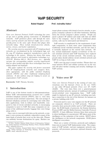
Voice Interface Cards (VICs)To install a voice network module, slide it into a slot in the router chassis (Figure 3). Use a number 1Phillips or small flat-blade screwdriver to fasten the module’s mounting screws.Figure 3Installing a Voice Network Module in a NET 1LNKACT1VOICE4VLNKACTSEE MANUAL BEFORE INSTALLATIONV1ETHERNET 0V0INPUT 100-240VAC 50/60HZ 3.0-1.5 AMPSENRouterModuleVoice Interface Cards (VICs)Voice interface cards install in slots in the voice network module, and provide connections to thetelephone equipment or network. Figure 4 shows a typical VIC.Figure 4Voice Interface CardSEE MANUAL BEFORE INSTALLATION0106951IN USEVICE&MIN USEVIC portsThere are three types of VIC interface: An FXS (foreign exchange station) interface connects directly to a standard telephone, faxmachine, or similar device. The FXS VIC interface supplies ringing voltage, dial tone, andsimilar signals to the station. Ports on this VIC are color-coded gray. An FXO (foreign exchange office) interface connects local calls to a public switched telephonenetwork central office, or to a PBX that does not support E&M signaling. This is the interface astandard telephone provides. Ports on this VIC are color-coded pink. E&M (ear and mouth) is a signaling technique for two-wire and four-wire telephone and trunkinterfaces. The E&M VIC connects remote calls from an IP network to a PBX for localdistribution. Ports on this VIC are color-coded brown.Each VIC provides two ports. You need one VIC port for each voice connection.You can install one VIC (two voice ports) in a one-slot voice network module, and two VICs (fourvoice ports) in a two-slot voice network module.Voice over IP Quick Start Guide5
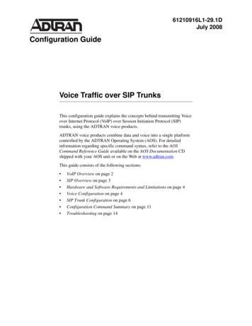
Installing Voice Network Modules and Voice Interface CardsTo install a VIC, slide it into a slot in the voice network module, as shown in Figure 5. Use anumber 1 Phillips or small flat-blade screwdriver to fasten the VIC’s mounting screws.Figure 5Installing a Voice Interface Card in a Voice Network Module2WOSERIALVOICE4VVICFXO0IN USEBRINT1B2IN USEB1ACT2EW12WNT13SEE MANUAL BEFORE INSTALLATION 0VICFXO1ETHERNET 0IN USELNK1SEE MANUAL BEFORE INSTALLATION 0H10842ETHERNET 1ACT1LNKACTV1IN USESEE MANUAL BEFORE INSTALLATIONV0ENINPUT 100-240VAC 50/60HZ 3.0-1.5 AMPSModuleRouter6 Voice over IP Quick Start Guide
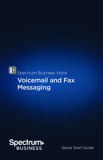
Connecting VICs to the NetworkConnecting VICs to the NetworkFigure 6 shows how to connect VICs to the network: Use a standard RJ-11 modular telephone cable to connect FXS VIC ports (color-coded gray) toa telephone or fax machine. Use a standard RJ-11 modular telephone cable to connect FXO VIC ports (color-coded pink) tothe public switched telephone network, or to a PBX that does not support E&M signaling,through a telephone wall outlet. The E&M VIC uses an RJ-48S connector and cable. The cable wiring depends on the type ofconnection. See the Voice Network Module and Voice Interface Card Configuration Note fordetails.Figure 6Connecting VICs to the Network1IN USEIN USEFXS VICSEE MANUAL BEFORE INSTALLATION0SEE MANUAL BEFORE INSTALLATION01IN USEIN USEE&M VICSEE MANUAL BEFORE INSTALLATION0PBX106911IN USEIN USEFXO VICWhen you are finished, reinstall any network interface cables you removed and turn ON power tothe router.Checking the InstallationIf you installed an FXS VIC, connect a handset to the VIC port. When router power is on, you shouldbe able to hear dial tone when you lift the handset. Dial tone should stop after you dial a digit. If youhave trouble, use the show voice port command to make sure that the VIC is installed correctly. Ifit is, try connecting a different handset to the VIC.Voice over IP Quick Start Guide7
Voice Port NumberingVoice Port NumberingCisco IOS configuration commands identify voice ports in the formrouter-slot/voice-slot/VIC-port12936Timesaver You can use the Cisco IOS show voice port command to identify the port numbers ofvoice interfaces installed in your router.Figure 7 shows Cisco 3620 router slot numbering.Cisco 3620 Slot NumbersH7238Figure 72WDO NOT INSTALL WAN INTERFACECARDS WITH POWER APPLIEDACTETHERNET 0ETHERNETETH 1 1LNKSERIALAUIENACTETHERNET 1LNKACTLNKACT1WO 2E W1SERIALINSTALLATIONACTBRINT1B2SEE MANUAL BEFORELNKB1ACTNT12EW12WAUIEN0ETHERNET 0Slot 1Slot 0Figure 8 shows Cisco 3640 router slot numbering.Figure 8Cisco 3640 Slot NumbersSlot 2Slot 32BRINT1WO 2E W1DO NOT INSTALL WAN INTERFACECARDS WITH POWER APPLIED2WSERIALETHERNET 0ETHERNET 1ACTSTPLNKAUIENLNKLNKACTSERIALETHERNET 1ACT1LNKACTSEE MANUAL BEFORE INSTALLATIONH6551B2ACTB1ACT2EW12WNT13AUIENETHERNET 0INPUT 100-240VAC 50/60HZ 3.0-1.5 AMPSSlot 18 Voice over IP Quick Start GuideSlot 0Power supply
ExampleFigure 9 shows voice slot numbering.Figure 9Voice Slot NumberingVoice slot 1Voice slot 0VOICE2VV1V010693ENFigure 10 shows VIC port numbering.VIC Port Numbering1IN USEVICE&MVIC port 0IN USEVIC port 1SEE MANUAL BEFORE INSTALLATION010694Figure 10ExampleSuppose you install a two-slot voice network module in the upper right slot of a Cisco 3640 router,and install two VICs in the module. Each VIC has two ports. From right to left, these ports wouldbe numbered 2/0/0, 2/0/1, 2/1/0, and 2/1/1.Voice over IP Quick Start Guide9
Entering Configuration ModeEntering Configuration ModeYou configure Cisco IOS software for voice over IP by typing commands on the command line. Thismethod of entering commands is called configuration mode.Note Voice over IP commands require the IP Plus, Desktop Plus, or Enterprise Plus image,Cisco IOS Release 11.3(1)T or later.To enter configuration mode, follow this procedure:Step 1Connect a console to the router. Configure the console for 9600 baud, 8 data bits, 1 stopbit, and no parity. Power up the router.Step 2If the current configuration is no longer valid (for instance, because you added aninterface), after about one minute you see the following prompt:Would you like to enter the initial configuration dialog? [yes]:Answer no. You now enter the normal operating mode of the router.Note If the current configuration is valid, you enter the normal operating modeautomatically.Step 3After a few seconds, you see the user EXEC prompt (Router ). Type enable and thepassword to enter enable mode:Router enablePassword:Configuration changes can be made only in enable mode. The prompt changes to theprivileged EXEC (enable) prompt (Router#):Router#Step 4Enter the config terminal command to enter configuration mode:Router# config terminalRouter(config)#The router enters global configuration mode, indicated by the Router(config)# prompt.Step 5If you have not configured the router before, or want to change the configuration,configure global parameters, passwords, network management, and routing protocols. Inthis example, IP routing, AppleTalk routing, and IPX routing are all enabled:Router(config)# ip routingRouter(config)# appletalk routingRouter(config)# ipx routingFor complete information about global configuration commands, and about configuringLAN and WAN interfaces on your router, refer to the Cisco IOS configuration guides andcommand references.10 Voice over IP Quick Start Guide
Entering Configuration ModeThe rest of this guide explains how to configure Cisco IOS software for voice over IP traffic.1293Timesaver Voice configuration uses a number of new Cisco IOS commands. For completeinformation about these commands, see the Voice over IP Software Configuration Guide. You canalso enter a question mark after a command or partial command at the Router(config)# promptto get help with syntax and arguments.6Remember that when you finish configuring the software, you must save the new configuration toNVRAM. This procedure is described in the section “Saving the Configuration” later in this guide.You may also want to save periodically during the configuration process.12936Timesaver At any point, you can see the current operating configuration, including changes youjust made, by entering the show running-config command.Voice over IP Quick Start Guide11
Configuring the IP Network for Real-Time Voice TrafficConfiguring the IP Network for Real-Time Voice TrafficVoice traffic is much more sensitive to timing variations than data traffic. For good voiceperformance, you might need to configure your data network so voice packets are not lost or delayed.This section describes three important methods of improving quality of service, or QoS (the level ofnetwork performance needed for voice over IP connections): RSVPMultilink PPP interleavingRTP header compressionCisco IOS software provides many other tools for ensuring QoS, such as custom queuing, priorityqueuing, weighted fair queuing, and IP precedence. For further information and more detailedexamples of QoS configuration, see the Voice over IP Software Configuration Guide.Note QoS measures the level of network performance. It does not directly measure the quality ofthe voice signal.Configuring voice over IP on a Frame Relay link involves special considerations. These arediscussed in the section “Configuring Frame Relay for Voice over IP.”Do You Need QoS?On a relatively low-bandwidth connection, such as a PPP or HDLC serial link, you should considerusing methods to ensure QoS. If you have a high-bandwidth network, such as Ethernet or FastEthernet, and voice and data traffic together occupy only a small fraction of the bandwidth available,you may not need to provide QoS. (See Figure 11.) If you are not sure, you may want to try skippingthe following sections and continuing with “Configuring FXS Interfaces” later in this guide. Returnto this section if you need to improve the reliability of voice connections.Figure 11Bandwidth v. Quality of ServiceHigh bandwidthMay not need QoS12 Voice over IP Quick Start Guide10689Low bandwidthNeed QoS
Do You Need RSVP?Do You Need RSVP?Resource Reservation Protocol (RSVP) enables routers to reserve enough bandwidth for reliableperformance. RSVP works well on PPP, HDLC, and similar serial line interfaces. It does not workwell on multiaccess LANs.You should configure RSVP if you have a serial interface and any of the following: Links slower than 2 MbpsLinks with high utilizationNeed for the best possible voice qualityNote If you configure multilink PPP interleaving, you can use the ip rtp reserve command insteadof configuring RSVP. See the next section on “Do You Need Multilink PPP Interleaving?”Configuring RSVPBy default, RSVP is disabled for compatibility with routers that do not implement it. To enableRSVP on an IP network, enter the ip rsvp bandwidth command from interface configuration mode.The following example shows how to configure RSVP on serial interface 0/0:Router enablePassword:Router# configure terminalRouter(config)# interface serial 0/0Router(config-if)# ip rsvp bandwidthThe default maximum bandwidth is 75 percent of the bandwidth available on each interface.RSVP must be enabled at each LAN or WAN interface that voice packets will travel across. Youmust also configure each remote dial peer to request an RSVP session, using the req-qos command.See the section “Calling Between Routers” later in this guide.Do You Need Multilink PPP Interleaving?On a dialer, ISDN PRI or BRI interface, or a virtual template, you can configure multilink PPPinterleaving, which helps to make sure that voice packets are transmitted without delay.You should configure multilink PPP interleaving if you have one of these interfaces, and either ofthe following: Point-to-point connections using PPP encapsulationLinks slower than 2 MbpsNote Do not use multilink PPP on links faster than 2 Mbps.Voice over IP Quick Start Guide13
Configuring the IP Network for Real-Time Voice TrafficConfiguring Multilink PPP InterleavingTo configure multilink PPP and interleaving on a dialer, ISDN PRI, or ISDN BRI interface, or avirtual template, you must first configure multilink PPP and interleaving on the interface or templateby entering the following commands in interface configuration mode:Router(config-if)# encapsulation pppRouter(config-if)# ppp multilinkRouter(config-if)# ppp multilink interleaveOptionally, configure a maximum fragment delay:Router(config-if)# ppp multilink fragment-delay millisecondsYou can also reserve a special queue for real-time packet flows to specified destination UDP ports,allowing real-time traffic to have higher priority than other flows. This command is needed only ifyou have not configured RSVP:Router(config-if)# ip rtp reserve lowest-UDP-port range-of-portsFor virtual templates only, apply the virtual template to the multilink bundle:Router(config-if)# multilink virtual-template 1Do You Need RTP Header Compression?RTP header compression on a PPP, HDLC, or similar serial interface compresses the packet headerto reduce network overhead.You should configure RTP header compression on a serial interface if you have either of thefollowing: Links slower than 2 MbpsNeed to save bandwidthNote Do not use RTP header compression on links faster than 2 Mbps.Configuring RTP Header CompressionEnable RTP header compression at both ends of the serial link by entering the following commandin interface configuration mode:Router(config-if)# ip rtp header-compression14 Voice over IP Quick Start Guide
Configuring Frame Relay for Voice over IPConfiguring Frame Relay for Voice over IPConfiguring voice over IP on a Frame Relay link involves certain special considerations to ensureacceptable voice quality. For Frame Relay links with slow output rates (64 kbps or less), where dataand voice are being transmitted over the same PVC, you should configure the following: Lower MTU size—Voice packets are generally small. If you decrease the MTU size to 300 bytes,large data packets can be broken up into smaller data packets that are more easily interleaved withvoice packets.The following example configures an MTU size of 300 bytes over serial interface 0/0:Router# interface serial 0/0Router(config-if)# mtu 300 RSVP—Configure RSVP on the subinterfaces (which correspond to PVCs) to reserve bandwidthfor voice channels. See the section on “Do You Need RSVP?” earlier in this guide.The following example configures RSVP over serial subinterface 0/0.1:Router(config-if)# interface serial 0/0.1 point-to-pointRouter(config-if)# ip address 192.168.19.0 255.0.0.0Router(config-if)# ip rsvp bandwidth RTP header compression—Configure RTP header compression on the subinterfaces to minimizethe size of the voice packet. See the previous section on “Do You Need RTP HeaderCompression?”The following command configures RTP header compression over the currently selectedsubinterface:Router(config-if)# frame-relay ip rtp header-compression Traffic shaping—Use traffic shaping to control the outbound traffic rate; otherwise, voice packetsmight be discarded. In Cisco IOS Release 11.3, Frame Relay traffic shaping is not compatiblewith RSVP. Use generic traffic shaping instead, setting the CIR equal to the port speed. Doingthis prevents the router from exceeding the CIR rate, which could lead to frames being discarded.The following command configures generic traffic shaping with a CIR of 32000 bps:Router(config-if)# traffic-shape rate 32000For further information and more detailed examples of Frame Relay configuration, see the Voiceover IP Software Configuration Guide.Voice over IP Quick Start Guide15
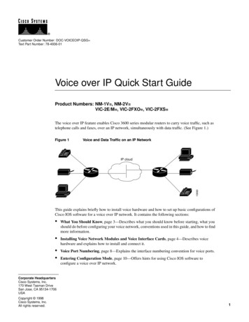
Configuring FXS InterfacesConfiguring FXS InterfacesThis section explains how to configure FXS VICs. Ports on this VIC connect directly to a standardtelephone, fax machine, or similar device.Figure 12 shows a basic voice network. A small business uses a Cisco 3600 series router (namedWest) to provide telephone and fax connections among employees in its office. Figure 12 shows twoof these telephones, each connected to an FXS VIC port in the West router.Figure 12Basic Voice Network (West Router)408 555-3737FXS VIC2/0/0IP cloudWestFXS VIC2/0/110007408 555-4141Note You can name your router by using the hostname command in global configuration mode.Table 1 lists telephone numbers and voice ports for the West router. (For information about portnumbering, see the section on “Voice Port Numbering” earlier in this guide.)Table 1West Router Telephone Numbers and Voice PortsTelephone NumberVoice Port408 555-37372/0/0408 555-41412/0/1Note Additional telephones and fax machines could be connected in this example, up to a total of12 if the router is a Cisco 3640 configured with three two-slot voice network modules. The modulein the remaining slot would provide interfaces for IP connectivity to the LAN or WAN and for datatraffic. To accommodate more than 12 voice devices, you would need to add more routers, or to usean E&M VIC and a local PBX, rather than connecting every telephone to its own FXS VIC.16 Voice over IP Quick Start Guide
Local Dial PeersLocal Dial PeersTo route a received voice call to the right destination, the router needs to know which telephonenumber belongs to each voice port. For instance, if a call comes in for 408 555-3737, the router needsto know that this telephone is connected to voice port 2/0/0 (as shown in Figure 12). In other words,the router needs to know the information in Table 1.To hold this information, Cisco IOS software uses objects called dial peers. A telephone number, avoice port, and other call parameters are tied together by associating them all with the same dial peer.Configuring dial peers is similar to configuring static IP routes—you are telling the router what pathto follow to route the call.Dial peers are identified by numbers, but to avoid confusing these numbers with telephone numbers,they are usually referred to as tags. Dial peer tags are integers that can range from 1 to 231 -1(2147483647), which should be enough for most purposes. Dial peers on the same router must haveunique tags, but you can reuse the tags on other routers.Table 2 assigns each phone number-voice port pair on the West router a dial peer tag. Within theallowed range, you can choose any dial peer tag or any system that is convenient or makes sense toyou. This type of dial peer is called a POTS dial peer or a local dial peer. The term “POTS” (plainold telephone service) means that the dial peer associates a physical voice port with a local telephonedevice. (Another type of dial peer is explained in the section “Calling Between Routers.”)Table 2West Router Local Dial PeersTelephone NumberVoice PortDial Peer Tag408 555-37372/0/0401408 555-41412/0/1402You should construct a table similar to Table 2 for your own routers, assigning your own telephonenumbers and dial peer tags.Note The telephone numbers used in this guide are only examples, and are generally invalid forpublic use in the United States. When you configure your network, be sure to substitute your owntelephone numbers.To configure the router with the information in the table, enter the following commands in globalconfiguration mode:West(config)# eer)#West(config)# eer)#West(config-dial-peer)#West(config)#voice 401 potsdest-pat 14085553737port 2/0/0voice 402 potsdest-pat 14085554141port 2/0/1exitThese commands are summarized in Figure 13.Voice over IP Quick Start Guide17
Configuring FXS InterfacesFigure 13West Router Configured for Local Dial Peersdial-peer voice 401 potsdest-pat 14085553737port 2/0/0IP cloudFXS VIC2/0/0WestFXS VIC2/0/110008dial-peer voice 402 potsdest-pat 14085554141port 2/0/1The dial-peer command always takes the argument voice. The number following it is the dial peertag, and pots is the type of dial peer.Cisco IOS software refers to a telephone number as a destination pattern, because it is thedestination for an incoming or outgoing call. Enter these numbers with the destination-pattern(abbreviated dest-pat) command. A destination pattern always begins with a plus sign ( ). It canalso include asterisks (*) and pound signs (#) from the telephone keypad, and commas (,) andperiods (.), which have special meaning. Parentheses ( () ), hyphens (-), slashes (/), and spaces ( ),which are often used to make telephone numbers easier for humans to read, are not allowed.Notice that the commands in the examples append the prefix 1 (used in the United States to indicatea long-distance number) and an area code to the destination pattern. You may need to include similarcodes for your country if the voice over IP equipment needs to establish a connection to the PSTN.In other situations, you might be able to simplify configuration by omitting this information.Note The Cisco IOS software does not check the validity of the telephone number. It accepts anystring of permitted characters as a valid number.The business that owns the West router also has a branch office in the East. Figure 14 shows the Eastnetwork, and Table 3 lists phone numbers, voice ports, and dial peer tags for this office.Figure 14Basic Voice Network (East Router)919 958-8282IP cloudFXS VIC3/1/0East919 958-959518 Voice over IP Quick Start Guide10009FXS VIC3/1/1
Local Dial PeersTable 3East Router Local Dial PeersTelephone NumberDestination PatternVoice PortDial Peer Tag919 958-8282 191995882823/1/0901919 958-9595 191995895953/1/1902The following commands configure local ports on the East Router:East(config)# eer)#East(config)# eer)#East(config-dial-peer)#East(config)#voice 901 potsdest-pat 19199588282port 3/1/0voice 902 potsdest-pat 19199589595port 3/1/1exitThese commands are summarized in Figure 15.Figure 15East Router Configured for Local Dial Peersdial-peer voice 901 potsdest-pat 19199588282port 3/1/0IP cloudFXS VIC3/1/0FXS VIC3/1/1dial-peer voice 902 potsdest-pat 19199589595port 3/1/110010EastChecking the ConfigurationIf you configured your router following these examples, you should now be able to place callsbetween telephones connected to the same router. You can also use the show dial-peer voicecommand to verify that the data you configured is correct.12936Timesaver If the voice port is offline, use the no shutdown command from interfaceconfiguration mode to enable it.Note Although placing calls directly between ports on the same router helps to verify yourconfiguration, it is not recommended for general telecommunications use.Voice over IP Quick Start Guide19
Configuring FXS InterfacesWild Cards and Number ExpansionOffice PBXs are usually configured so a user can dial a local call (within the same PBX) by dialingthe extension only—for instance, the four-digit extension 3737 or the five-digit extension 53737instead of the full telephone number, 1 408 555-3737.You can provide the same shortcut on a voice over IP network by using the number-expansion(num-exp) command. This command tells the router to expand a particular sequence of dialednumbers into a complete telephone number (destination pattern). For instance, to expand 3737 into408 555-3737, enter the following command:West(config)# num-exp 3737 14085553737To expand 4141 into 1 408 555-4141, enter the following command:West(config)# num-exp 4141 14085554141More generally, you can use the period (.) as a wild-card character representing a s
2 Voice over IP Quick Start Guide Configuring the IP Network for Real-Time Voice Traffic, page 12—Describes how to configure the IP network to accommodate voice traffic. Configuring FXS Interfaces, page 16—Describes how to configure FXS voice interface cards for connecting a router to telephones, fax machines, and similar devices.