Transcription
Desalination and Water Purification Researchand Development Program Report No. 120Dewvaporation Desalination5,000-Gallon-Per-Day Pilot Plant\U.S. Department of the InteriorBureau of ReclamationJune 2008
Form ApprovedOMB No. 0704-0188REPORT DOCUMENTATION PAGEPublic reporting burden for this collection of information is estimated to average 1 hour per response, including the time for reviewing instructions, searching existing data sources, gathering and maintainingthe data needed, and completing and reviewing this collection of information. Send comments regarding this burden estimate or any other aspect of this collection of information, including suggestions forreducing this burden to Department of Defense, Washington Headquarters Services, Directorate for Information Operations and Reports (0704-0188), 1215 Jefferson Davis Highway, Suite 1204, Arlington, VA22202-4302. Respondents should be aware that notwithstanding any other provision of law, no person shall be subject to any penalty for failing to comply with a collection of information if it does not display acurrently valid OMB control number. PLEASE DO NOT RETURN YOUR FORM TO THE ABOVE ADDRESS.1. REPORT DATE (DD-MM-YYYY)TT2. REPORT TYPETJune 20083. DATES COVERED (From - To)TTTFinalOctober 2007 – January 20084. TITLE AND SUBTITLE5a. CONTRACT NUMBERTDewvaporation Desalination5,000-Gallon-Per-Day Pilot PlantAgreement No. 03-FC-81-09055b. GRANT NUMBER5c. PROGRAM ELEMENT NUMBER6. AUTHOR(S)5d. PROJECT NUMBERDr. James R. Beckman5e. TASK NUMBER5f. WORK UNIT NUMBER7. PERFORMING ORGANIZATION NAME(S) AND ADDRESS(ES)8. PERFORMING ORGANIZATION REPORTNUMBERL’Eau LLC1937 E. Calle de ArcosTempe, Arizona 852849. SPONSORING / MONITORING AGENCY NAME(S) AND ADDRESS(ES)10. SPONSOR/MONITOR’S ACRONYM(S)U.S. Department of the Interior,Bureau of Reclamation, Denver Federal Center,PO Box 25007, Denver CO 80225-0007Reclamation11. SPONSOR/MONITOR’S REPORTNUMBER(S)DWPR Report No. 12012. DISTRIBUTION / AVAILABILITY STATEMENTAvailable from the National Technical Information Service (NTIS),Operations Division, 5285 Port Royal Road, Springfield VA 2216113. SUPPLEMENTARY NOTESTReport can be downloaded from Reclamation Web site: s.html14. ABSTRACT (Maximum 200 words)A 5,000-gallon-per-day dewvaporation pilot plant was designed, built, and operated at the 23rd Avenue Waste WaterTreatment Plant (WWTP) in Phoenix, Arizona. The City of Phoenix Water Services Department, along with the Bureauof Reclamation Phoenix Area Office, cooperated to establish a pilot plant site. The pilot plant feed was theconcentrate from a Tactical Water Purifier System reverse osmosis (RO) unit with ultrafiltration pretreatment. A2,000-milligram-per-liter (mg/L) total dissolved solids (TDS) waste water RO concentrate stream was treated by the pilotplant to more than 45,000 mg/L of TDS brine and 10 mg/L of TDS distillate. Recovery varied from 70 percent to100 percent, with no decrease in distillate rate or increase in distillate contamination. Thermal multiple effects variedfrom 2.0 to 3.5, which was less than the 5.0 effects demonstrated prior to transport to the WWTP site. Operating costwas highly dependent of the price of fuel. Using the average of the three best thermal multiple effect values of 3.2 andnatural gas cost of 0.80 per therm, the operating cost of water would be 20.85 per 1,000 gallons. The use of waste heator solar thermal would reduce the operating cost to the cost of water pumping and air blowing. Power needs of 0.5kilowatthour (kWh) per 1,000 gallons at 0.10 per kWh would amount to 0.05 per 1,000 gallons.15. SUBJECT TERMSWaste water treatment, desalting, thermal desalination, dewvaporation, reverse osmosis (RO) concentrate16. SECURITY CLASSIFICATION OF:17. LIMITATION18. NUMBEROF ABSTRACTOF PAGESULa. REPORTb. ABSTRACTULULc. THIS PAGEULSAR (sameas report)6019a. NAME OF RESPONSIBLE PERSONMichelle Chapman19b. TELEPHONE NUMBER (include areacode)(303) 445-2264S Standard Form 298 (Rev. 8/98)P Prescribed by ANSI Std. 239-18T
Desalination and Water Purification Researchand Development Program Report No. 120Dewvaporation Desalination5,000-Gallon-Per-Day Pilot PlantPrepared for Reclamation Under Agreement No. 03-FC-81-0905byJames R. BeckmanL’Eau LLCTempe, ArizonaU.S. Department of the InteriorBureau of ReclamationTechnical Service CenterWater and Environmental Resources DivisionWater Treatment Engineering Research TeamDenver, ColoradoJune 2008
MISSION STATEMENTSThe mission of the Department of the Interior is to protect and provideaccess to our Nation's natural and cultural heritage and honor our trustresponsibilities to Indian tribes and our commitments to islandcommunities.The mission of the Bureau of Reclamation is to manage, develop, andprotect water and related resources in an environmentally andeconomically sound manner in the interest of the American public.AcknowledgmentsThis work was initially supported by the Department of the Interior, Bureau ofReclamation under Agreements No. 98-FC-81-0049 and 99-FC-81-0186. Theengineering team wishes to thank Ms. Michelle Chapman (Reclamation - Denver),Mr. Thomas Poulson (Reclamation - Phoenix), Mr. William Cosgrove (Reclamation Phoenix) and Mr. Henry Day (City of Phoenix) for their support, encouragement, andsuggestions.The principal investigator, along with the engineering team of Mr. Victor Banks,Mr. Joshua Brown, Mr. Michael Dorr, Mr. George Finnegan, and Mr. StephenPoplawski also wish to express their appreciation for the patience needed throughoutthis initially anticipated 2-year program.DisclaimerThe views, analysis, recommendations, and conclusions in this report are those of theauthors and do not represent official or unofficial policies or opinions of the UnitedStates Government, and the United States takes no position with regard to anyfindings, conclusions, or recommendations made. As such, mention of trade namesor commercial products does not constitute their endorsement by the United StatesGovernment.
Table of ContentsPageAbbreviations and Acronyms .1. Executive Summary .2. Background and Introduction .2.1 Dewvaporation Philosophy.2.2 Dewvaporation Model .2.3 Tower Details.2.4 Pilot Plant Construction .2.5 Pilot Plant Objectives.2.5.1 Initially Proposed Pilot Plant Approach .2.5.2 Pilot Plant Goals and Objectives.2.6 Pilot Plant Operational Risks .2.7 Projected Dewvaporation Economics .2.8 Project Management .2.9 Facilities and Equipment.2.10 Environmental Impact.2.11 Dismantling the Pilot Plant .2.12 Dewvaporation Project Relevance to Desalination andWater Purification Research Objectives .3. Results, Conclusions, and Recommendations .3.1 Pilot Plant Results .3.2 Improvement Recommendations .3.2.1 Tandem Arrangement .3.2.2 NEWT Tower Manufacturing.3.2.3 Solar Hot Water .3.2.4 Desiccant Heat Pumping.4. Work Performed.4.1 Changing Design Basis from 10,000 gpd to 5,000 gpd .4.2 Design Modifications.4.2.1 Independent “Unit Cell” Turnarounds .4.2.2 Wide 33-Inch Towers .4.2.3 Narrow Gauge 3-mm 526313132323233iii
Table of ContentsPage4.2.4 Parallel Pathways .4.3 Manufacturing Capacity.4.3.1 NAS-T Design and Operation.4.3.2 NAST-C Tower Design .4.3.3 Transportation of Towers to WWTP .4.3.4 Install Towers at WWTP .4.4 Year 2 (October 2004 - September 2005).4.4.1 NAS-TC Tower Design and Operation.4.4.2 Pilot Plant Overview .4.4.3 Electrosteam Boiler Operational.4.4.4 RO Unit Operational .4.4.5 New Towers on Site.4.5 Year 3 (October 2005 - September 2006).4.6 Year 4 (October 2006 - April 2007) .4.6.1 Measurements .4.6.2 General Waste Water Feed Operation .4.6.3 RO Concentrate Feed Operations .5. Economics.6. Reference List .33333435353536363637383839404041414547AppendicesA Pilot Plant OperationalB City of Phoenix Water AnalysisC Metric ConversionsList of TablesTable1234ivPlot Plant Design Data .Desiccant Drying Cities .Initial Towers Built .Towers Built for Transport to Phoenix .Page22283233
List of Dewvaporation tower design .Volatile organic carbon removal and evaporation pondreclamation with dewvaporation.Edge view of 4-millimeter, twin-wall polypropylene sheet.Tower sections fitted with gauze .Top view of the tower .Towers at the manufacturing site.Towers installed at pilot site with generator, tanks, and tacticalwater purification system.First tower set with steam generator and tanks.Arrangement of towers for the pilot test .Single tower standard and modified air design.Proposed tandem air flow arrangement .NEWT air turnarounds.Solar hot water heating .Desiccant heat pumping with boiler .Desiccant heat pumping with air drying .Overview picture of the as-built pilot plant .Tactical water purification system (vibration testing) .Electric steam boiler in its enclosure .Standardized towers from L’eau.Feed tank salinity – semibatch run.Tower basin design .Tower salinity – semibatch run.20,000-gpd dewvaporation plant footprint .Page45101011111213132424252526273737383942434345v
GlossaryAcpBFGhhkLMNPwPPfQqRRHSTtUVwheat transfer area (ft2)heat capacity (BTU/lbmole F)14 (SI) 16.38 (American Engineering)feed flow rate (lbmole/sec)carrier gas flow rate (lbmole/sec)molar enthalpy (BTU/lbmole)heat transfer coefficient (BTU/hr ft2 F)thermal conductivity (BTU/hr ft F)liquid flow rate at any position in the tower (lbmole/sec)mass transfer factormolar flow rate (lbmole/sec)vapor pressure of water (psia)total pressure (psia)production density (lb/hr ft2)energy input at the top of the tower (BTU/sec)heat flux (BTU/hr ft2)gas constant (BTU/lbmole F)relative humiditysalinity at any position in the towertemperature ( F)thickness of heat transfer wall (ft)overall heat transfer coefficient (BTU/hr ft2 F)vapor loading (lbmoles of water vapor per lbmole of gas)width of the flow media (ft)SubscriptsBDdebrine streamdistillate streamdewformation sideevaporation sidevii
Subscripts (continued)fgh0refRHLMliquid filmgastop of the towerbottom of the towerreference pointrelative humiditylogarithmic meanGreekλδΓρµviiiheat of vaporization of water (BTU/lbmmole)liquid film thickness (ft)gamma (lb/hr ft)Density (lb/ft3)viscosity (lb/ft sec)
Abbreviations and WTPXAOTDSTWPSacrylonitrile butadiene styreneArizona State Universitygallons per daygallons per pounds per hourpounds per square inchmilligrams per litermillimetersa unit with air flowing up or North on theevaporation side And then flowing South ordown on the dew formation side of the Tower.a tower where the air flow pattern is first Northon the evaporation side and then East and Westor zigzag on the downward flow path on the dewformation side of the Tower.Phoenix Area Officetotal dissolved solidstactical water purification systemix
1. Executive SummaryDewvaporation is a specific process of humidification-dehumidificationdesalination, which uses air as a carrier-gas to evaporate water from saline feedsand form pure condensate at constant atmospheric pressure. The heat needed forevaporation is supplied by the heat released by dew condensation on oppositesides of a heat transfer wall. Since external heat is needed to establish atemperature difference across the wall, and since the temperature of the externalheat is versatile, the external heat source can be from waste heat, from solarcollectors, or from fuel combustion. The unit is constructed out of thin waterwettable plastics and operated at atmospheric pressure.A 5,000 gallon-per-day (gpd) dewvaporation pilot plant was designed, built, andoperated at the 23rd Avenue waste water treatment plant (WWTP) in Phoenix,Arizona. The City of Phoenix Water Services Department, along with the Bureauof Reclamation Phoenix Area Office cooperated to establish a pilot plant site.The pilot plant feed was the concentrate from a Tactical Water Purifier Systemreverse osmosis (RO) unit with ultrafiltration pretreatment.A 2000-milligram-per-liter (mg/L) total dissolved solids (TDS) wastewaterRO concentrate stream was treated by the pilot plant to more than 45,000 mg/LTDS brine and 10 mg/L TDS distillate. Recovery varied from 70 percent to100 percent with no decrease in distillate rate or increase in distillatecontamination. Thermal multiple effects varied from 2.0 to 3.5, which was lessthan the 5.0 effects demonstrated prior to transport to the WWTP site. Distillateproduction rate varied among towers, producing approximately 5 gallons perminute (gpm) per tower, which was less than the target rate of 8.3 gpm.Operating cost was highly dependent on the price of fuel. Using the average ofthe three best thermal multiple effect values of 3.2, and natural gas cost of 0.80 per therm, the operating cost of water would be 20.85 per 1,000 gallons.The use of waste heat or solar thermal would reduce the operating cost to the costof water pumping and air blowing. Power needs of 0.5 kilowatthours (kWh) per1,000 gallons at 0.10 per kWh would amount to 0.05 per 1,000 gallons.1
2. Background and IntroductionMany technologies have been used to perform desalination, resulting in preferredtechnologies based on economics (Fosselgard and Wangnick [1]). For example,in the desalination of mild brackish (less than 1,000 milligrams per liter (mg/L)TDS) water, reverse osmosis (RO) is superior to all desalination technologies.This is mainly a reflection of the fact that other technologies involve phasechange (boiling), whereas RO employs low-pressure pumps (less than 100 poundsper square inch (lb/in2) (7 bar)) to move water through semipermeablemembranes, resulting in less energy consumption than that involved in a boilingprocess. One area where RO is ineffective in water purification is in the treatmentof waters containing nonfilterable suspended particulates. For example, theColorado River contains silt in the 1-micron range, which tends to foulRO membranes, increasing the maintenance and/or pretreatment costs ofRO operation.For the more TDS intense aqueous applications such as RO concentrates(Mickley [2]), waste streams, and seawater, other mechanical and thermaltechnologies economically compete with RO, as seen by Larson et al. [3], [4]. Inthe case of seawater desalination, the RO pump pressure increases to 1,200 lb/in2(80 bar) and feed waters require extensive pretreatment in order to protect andextend the life of the membranes.The competitive technologies to RO for seawater desalination include mechanicalvapor compression (MVC), multi-stage flash distillation, and multi-effectdistillation with and without thermal vapor compression. The MVC needs shaftpower to drive its compressor. The motor can be either electrically or thermallydriven. For electrically driven MVC, MVC plants consume more electricity thanRO units in the same seawater service. The other processes dominantly use andreuse heat as the main driver to affect temperature-driving force between boilingand condensing at staged pressures. The thermally driven plants attempt to reusethe high temperature applied heat as many times as is economically possible tominimize operating costs. This energy reuse factor economically varies from 6 to12.2.1 Dewvaporation PhilosophyThermal processes that operate below the boiling point of water are calledhumidification/dehumidification (HDH). Younis et al. [5] investigatedHDH units using solar energy as the external heat source. Just like thesteam-driven external heat operation of an HDH, two heat transfer towers (orzones) are required to transfer heat from a massive flow of water. The water is3
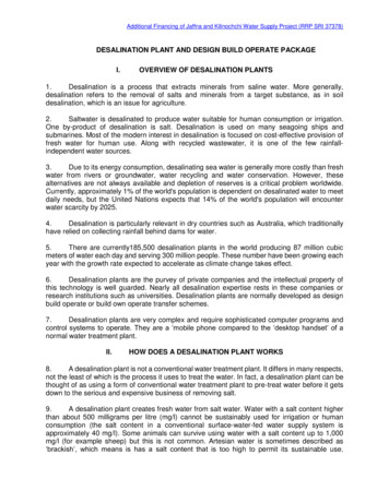
used as both an internal heat source and internal heat sink. The requirement oftwo towers makes the HDH process energy inefficient. The dewvaporationtechnique belongs to the HDH family of technology but requires only one towermaking it more energy efficient.The Arizona State University (ASU) patented technology (Beckman [6]),dewvaporation, is applicable to desalination and reclamation of seawater, brackishwater, evaporation pond water, RO plant concentrates, chemical mechanicalplanarization slurries from the semiconductor industries, volatile organic (methyltertiary butyl ether, trichloroethylene) contaminant removal from ground, andother impaired sources. Dewvaporation’s most economic niche is in small plantapplications. Larger plants will evolve in time.The standard dewvaporation continuous contacting tower is a relatively new,nontraditional, and innovative heat driven process using air as a carrier-gas andremaining at atmospheric pressure throughout the device. The external heatsource can be from low temperature solar (131 F [55 C]), waste heat, orcombustible fuels (210.2 F [99 C]). Briefly, the process works for brackishdesalination, as viewed in figure 1 (Beckman [7]; Beckman, Hamieh, andYbarra [8]; and Hamieh, Beckman, and Ybarra [9]).A carrier-gas, such as air, isbrought into the bottom of thetower on the evaporation side of a190.2oF189.5oFheat transfer wall at a typical wetVdh 1.81Veh 1.71bulb temperature of 69.8 F(21 C), thereby containing aboutRH 100%0.025 moles of water vapor permole of air. The wall is wettedby saline feed water, which is fedinto the evaporation side at thef 16.8top of the tower. As the airmoves from the bottom to the topof the tower, heat is transferredRH 100%into the evaporation side throughoothe heat transfer wall, which69.8 F119.7 Fallows the air to rise inVe0 0.025Vd0 0.125temperature and evaporate waterFigure 1. Dewvaporation tower design.from the wetting saline liquid,which coats the heat transferwall. Concentrated liquid leaves from the bottoms of the towers, and hotsaturated air leaves the tower from the top at 189.5 F (87.4 C) with a humidityof 1.71 moles of water vapor per mole of air. Heat is added to this hot air by anBrackish WaterQ4
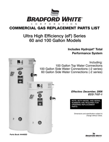
external heat source (steam was used in this investigation), increasing the airhumidity and temperature to a vapor loading of 1.81 and 190.2 F (87.9 C),respectively. This hotter saturated air is sent back into the top of the tower on thedew formation side. The dew formation side of the tower, being slightly hotterthan the evaporation side, allows the air to cool as condensation heat is transferredfrom the dew formation side to the evaporation side. Finally, pure watercondensate and saturated air leave the dew formation side of the tower at thebottom at 119.7 F (48.7 C). Total external heat needed is made up of the heatadded at the top of the tower to establish a heat transfer temperature differenceand the heat needed to establish a temperature offset between the saline feed stockand the pure water condensate used to produce steam. The detrimental effect ofsalt concentration on the energy reuse factor (or gain output ratio), f, is explainedin the theory section.Figure 2a illustrates that volatile organic carbon removal behaves ideally as thedistillation of almost pure, brackish, or sea water. The reclamation of evaporationpond waters that are saturated with salts (20 percent by weight), as shown infigure 2b, is more difficult. The feed waters are processed to extinction by therecycle of bottoms brine back to the feed. The two products are distillate and wetsalt solids.Due to the slight desiccant effect of salts, the energy reuse factor decreases withincreased salt concentrations. This suppressed vapor pressure of water reducesthe relative humidity of saturated air, causing the addition of more steam to makeup the air dryness.Figure 2. Volatile organic carbon removal and evaporation pond reclamationwith dewvaporation.5
2.2 Dewvaporation ModelFrom figures 1 and 2, the mathematical definition of the energy reuse factor, f, isthe ratio of the energy transferred through the heat transfer wall to the hightemperature energy input, as shown in equation 1 (Beckman [7], [10]):f Vdh Vd 0Vdh Veh(1)The definition of the molar production flux, Pf , is the gas traffic (mol of air persecond) times the water vapor decrease on the dew formation side of the walldivided by the wall area, as shown in equation 2:Pf G (Vdh Vd 0 )A(2)Typically, the feed/condensate temperature offset is kept to 10 F (5.6 C). Thiscan be accomplished by either an internal or external feed heat exchanger. In thisanalysis, the energy reuse factor, f, was 16.8. By including the heat needed forthe temperature offset, the factor reduces to about 13. Actually, the product of thefactor and the molar production flux, Pf , is a constant at parametric Veh. Thevalue of the constant is a function of the operating variables, as shown in thefollowing equations.The amount of water vapor contained in the air carrier-gas is calculated byspecifying the temperature, T, and calculating the vapor pressure, Pw, fromequation 3 (Smith and Van Ness [11]):ln Pw B λ0R T(3)where B and λ0 are constants obtained by fitting a straight line to the ln(Pw)versus 1/T for the steam table. For temperature range of 32 – 212 F (0 – 100 C),B is 14 and λ0/R is 5209 K (Perry, Green, and Maloney [12]). The carrier-gasvapor content (moles of water vapor per mole of air) is:V RH PwP RH Pw(4)where the relative humidity (RH) is given as a function of salinity, S gramssalt/liter, by the following equation (Spiegler and Laird [13]):RH 1 0.000538 S6(5)
The hottest temperature in the evaporating section is specified, allowing thecalculation of the largest value of the Veh in the evaporating section of the unit.Then the change in vapor content of the carrier-gas is specified across the top ofthe tower by:(6)ΔV Vdh VehFrom these specifications, the temperature difference across the heat transfer wallat any position can be described as:1ΔTLM(z B 2 R 1 ΔV Ve ΔV λ0 z) Ve z (7)In this process, both the film heat and mass transfer coefficients are important inestablishing the overall effective heat transfer coefficient, U. For simultaneousheat and mass transfer operations involving air and water, the Lewis Number isessentially unity (McCabe, Smith, and Harriott [14]), allowing the coefficients tobe related by similitude as ky hg/cp. The effect of the latent energy associatedwith the mass transfer of water vapor can be related to the sensible heat transferassociated with the air/vapor mixture by equation 9 after Werling [15].hfz()(8) V (9) hg 1 M zzwhere M is expressed as:2 λ0 RM RT c pTaking into account both gas film heat transfer coefficients and the thermalresistance of the heat transfer wall, then the overall effective heat transfercoefficient, U, can be expressed as:111t U z h fe z h fd z k(10)The heat transferred through the heat transfer wall is essentially the latent heat, atthe system temperature needed to evaporate water as:(q z G λ Vez Δz Vez)(11)The area needed for the heat transfer wall is obtained by an energy balance (Bird,Stewart, and Lightfoot [16]).7
Azqz 11 U z ΔTLM(12)zWhere:ΔTLM Tyd Tye(13)Upon integrating with respect to the overall area and assuming that t/k is smallcompared to the gas phase resistance, equation 14 then relates the total energyreuse factor, f, and the total production flux, Pf , as follows: λ0 2 hg Vehf Pf B R T C p 2 Veh λ0 .(18) FRH λ (14)Where the detrimental effect, FRH, of reduced relative humidity at the tower topexiting evaporation air stream, RH, is:FRH 1 (1 RH ) (1 f ) (1 Veh )(15)Equation 14 shows that as the temperature increases, the product of energy reusefactor and molar production flux become greater. It is also apparent that theenergy reuse factor, f, and the molar production flux, Pf, are relatedhyperbolically in an established unit. The detrimental effect of salt concentrationis also included in this expression from equation 15.Additionally, higher values of Veh; i.e., higher temperatures, improve both f andPf values, which is economically beneficial to the tower. However, highertemperatures are limited to the heat source temperature and the normal boilingpoint of water.On the other hand, by taking into account the heat conduction resistance in theplastic heat transfer wall and the resistances due to the two liquid films on thewall, then:2 λ0 hgPf f B R T c p Veh 2 Veh λ0 18 F λ (16)With:F 11 FRH Fε FRH8 6 3 Veh Fε 3 2 Veh (17)
The resulting equation is 18. This expression resembles equation 14, but with anadditional term F containing all of the plastic and liquid films resistances to heattransfer. Rearranging these equations into a form that would be linear in a dataplot gives: λ0 λ c p (3 2 Veh )Pf f hg 2 Veh 3 V 2 V 2eheh Air Boundary Layer B2 Rt 6k (18)Wall and LiquidsEssentially, the manner in which equation 18 (Hamieh [17]) is used todetermine the effective heat transfer area from the data obtained per run. All ofthe parameters on the right hand side of equation 18 are known. Data from eachrun contain the temperature at the top of the tower, production rate, and energyconsumed. From the tower top temperature, the water vapor to air ratio andenergy reuse ratio can be calculated. Therefore, the production density can beassessed on the left hand side of equation 18. Since the production rate is data,then the effective heat transfer area in the tower can be identified. The effectivearea is a property of the tower mechanical design, as summarized by Hamieh andBeckman [18], [19].2.3 Tower DetailsThe plastic heat transfer wall that best offered low-cost economics, dimensionalstability, free flow zones, manufacturability, and availability was twin-wallextrusions found in Spring 2001. The twin-wall extruded plastics are available inmany sizes (thickness) ranging from 2 millimeters (mm) to 10 mm. Coroplast,Incorporated’s (1-800-666-2241) twin-wall, 4-mm, polypropylene extruded sheetwas purchased at 5.25 per 4-foot by 8-foot s
Treatment Plant (WWTP) in Phoenix, Arizona. The City of Phoenix Water Services Department, along with the Bureau of Reclamation Phoenix Area Office, cooperated to establish a pilot plant site. The pilot plant feed was the concentrate from a Tactical Water Purifier System reverse osmosis (RO) unit with ultrafiltration pretreatment. A