Transcription
BULETINUL INSTITUTULUI POLITEHNIC DIN IAŞIPublicat deUniversitatea Tehnică „Gheorghe Asachi” din IaşiVolumul 67 (71), Numărul 1, 2021SecţiaELECTROTEHNICĂ. ENERGETICĂ. ELECTRONICĂDOI:10.2478/bipie-2021-0002DIGITAL COMMUNICATION LINKS COOPERATING WITHTHE ANALOG 4-20 mA STANDARD FOR MARINEAPPLICATIONSBYMOSTAFA ABOTALEB1, , JANUSZ MINDYKOWSKI2, BOLESLAW DUDOJC2and ROMUALD MASNICKI21Gdynia Maritime University, Doctoral School,Morska 81-87, 81-225 Gdynia, Poland2Gdynia Maritime University, Faculty of Electrical Engineering,Morska 81-87, 81-225 Gdynia, PolandReceived: March 29, 2021Accepted for publication: July 26, 2021Abstract. The maritime industry makes a significant contribution to theglobalized economy. One of the most important parts of the maritime industry istransport. Maritime transport by ships is the dominant means of transport forindustrial products and food. Modern ships are increasingly automated. Acharacteristic feature of automation systems is the use of distributed monitoringand control systems with large distances between field devices and controllers.Among many methods of signal transmission, both in measurement andcontrol, the dominant role in related to continuous signals is played by the twowire 4-20 mA current standard. Despite its advantages, this standard haslimitations mainly due to one-way transmission of information representing onemeasurement quantity. Programmable transducers are an alternative to analoguesolutions. This carried out research concentrates on the full assessment of theproperties of the considered methods of information transmission used so farwith particular reference to the two-wire 4-20 mA standard. This assessment alsotakes into account the negative factors characterizing the sea-going ships, such asenvironmental conditions or problems resulting from the use of an isolated Corresponding author; e-mail: m.abotaleb@sd.umg.edu.pl 2021 Mostafa Abotaleb et al.This is an open access article licensed under the Creative Commons Attribution-NonCommercialNoDerivatives 4.0 International License (CC BY-NC-ND 4.0).
22Mostafa Abotaleb et al.power grid. Additionally, a description of the available digital methods used forcommunication in ship automation systems will be presented. Firstly, descriptionwill be provided for HART protocol (Highway Addressable RemoteTransducer), Foundation Fieldbus, Profibus PA and Modbus as communicationprotocols adopted by modern smart transducers as alternatives for classicalanalogue 4-20 mA transducers. Moreover, serial communication interfaces suchas RS232, RS422 and RS485 will be discussed as means of communicationbetween automation stations. In order to demonstrate the positive contributionfor smart transmitters in measurement and control process, an experimentalresearch has been conducted at the laboratories of Gdynia Maritime University,results of which will be discussed in detail in this article. Eventually, illustrationwill be provided for tank level measurement systems on a commercial ship as anexample for measurement and control system mainly based on classical 4-20 mAcurrent signal. Description will be provided for the problems associated with thesystem and their causes. Based on the conducted discussions, there will berecommendations of suggested solutions for such problems.Keywords: 4-20mA standard; HART; Foundation Fieldbus; Profibus PA;Smart Transducers.1. IntroductionThe maritime industry has many sectors, a very important part of whichis related to maritime transport. Maritime transport is carried out by varioustypes of ships such as cruises, ferries, containers, general cargo, bulk carriers,chemical ships, oil, LPG, LNG and others. The general characteristics of themeasurement and control systems in the engine room and on board for any ofthese ships are almost similar, except for some differences that may distinguishsome ships from others depending on the type of the ship. The subject ofMeasurement and control systems on ships is an important topic to discuss froma technical, scientific and practical perspective (Chun-ming, 2016) in order toimprove their performance in the marine environment. Sea conditions arecharacterized by the induction of disturbances, distortions as well as attenuation,negatively affecting the measured electrical signals used in these systems,especially when additional factors such as humidity, vibration and frequentvariation of ambient temperature are taken into account (Dudojc andMindykowski, 2019).Sensors and transducers are used to convert measured process variablesinto electrical on/off signals, analogue signals, hybrid analogue signals anddigital signals. Afterwards, these electrical signals are processed by hostcontrollers such as PLCs (Programmable Logic Controllers) or by DistributedControl System (DCS). On/off sensors provide means of conversion for specificvalue of the process variable so that the control system can activate an alarm.Unlike on/off signals, analogue signals provide continuous conversion ofmeasured process variable.
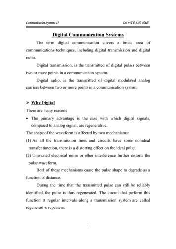
Bul. Inst. Polit. Iaşi, Vol. 67 (71), Nr. 1, 202123Smart transducers provide a means of detection for any negativeinfluences that might be induced by harsh environmental conditions as waspreviously mentioned. Hybrid analogue smart transducers such as HARTtransducers or digital smart transducers such as Foundation Fieldbus andProfibus PA transducers, each of them provides a specific mechanism based onwhich the performance of measurement and control process is continuouslyevaluated. Loop Characterization and Static Process Monitoring (SPM) are twoexamples of mechanisms adopted by programmable transducers for the purposeof deriving statistical information from the measurement process readings todetect any kind of abnormalities that might negatively affect the measurementor control process.As an example of measurement and control systems on ships, a briefdescription will be provided for tank level measurement. This article will referto such a case study in which problems associated with tank level measurementsystem will be analyzed in the context of being a measurement and controlsystem mainly based on the classic analogue 4-20 mA standard, especially thatboth the transmitters and the actuators used in the system are 4-20 mA analoguedevices.2. Two Wire 4-20 mA Analogue StandardAnalogue measurement and control signals provide means ofinterpretation for the measured or controlled quantity into an electrical currentor voltage standard signals. This interpretation is done by various types oftransducers which differ in their measurement mechanism structure according tothe measured quantity, for example temperature, pressure or flow. There aremany analogue measurement and control standard signals such as 0-20 mA,4-20 mA, 1-5 V, 0-5 V and -10 to 10 V (Snyder, 2008). Among all theseanalogue signals, 4-20 mA signal is the most widely used due to its non-zerolower range limit (20% offset). The 20% offset of 20 mA allows for theimplementation of two-wire connection between the transducer and an indicatoror controller.In its simply forms of two-wire 4-20 mA current loop presented in Fig. 1consists of analogue transducer, which actually is a controlled passive source ofcurrent (sink type), power supply from source of voltage Ups and seriesresistance of indicator Ri and two cable resistances Rc. The sum of all seriesresistances in current loop is represented by load resistance RL. In industrycondition, the current loop presented in Fig. 1 can be named as a measurementline due to the very long distance between the transducer and the place ofindication of measured quantity. The indicator resistance Ri can be the internalresistance of milli-ammeter which is calibrated to the measured quantity or theinternal resistance of any SCADA (Supervisory Control & Data AcquisitionSystem) analogue input card.
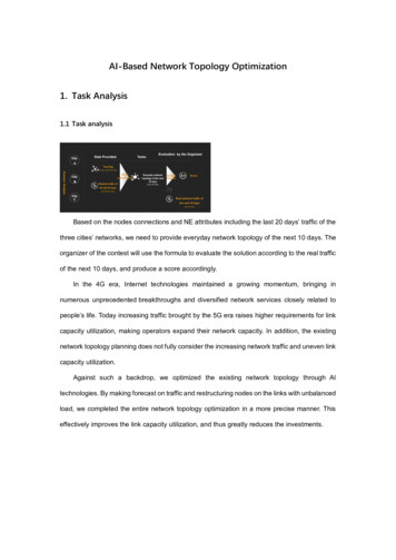
24Mostafa Abotaleb et urrentloopRiRc Y-00003-2Umin, UmaxUpsLong distance of cableFig. 1 – Measurement line of two-wire 4-20 mA standard.The current loop can be supplied by external power supply or by thecontrol system analogue input card to which the measurement line is connected.For analogue input card, the value of the resistance Ri is dependent on thevoltage analogue signal to which the 4-20 mA current signal will be converted.Practically in the current loop, it can be connected some differentindicators, analogue inputs cards or other kinds of equipment. Each of thesekinds has its own input resistance. For each measurement line there is a limit forequivalent load resistance RL which is expressed by equation: RL (UpsUmin)/Imax. In case was equal to 20 mA, the equation will be RL 0.05‧(UpsUmin) [kΩ]. This condition can be graphically presented as illustrated in the Fig.2 by operating region of two-wire measurement line in 4-20 mA standard.RL [Ω]RLmaxCRQQBAY-00001-3UminUQU [V]UmaxFig. 2 – Operating region of the measurement line in 4-20 mA standard, where Umin,Umax are the admissible range of voltage for transducer.
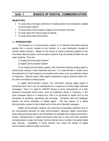
Bul. Inst. Polit. Iaşi, Vol. 67 (71), Nr. 1, 202125For each real two wire measurement line, only one voltage supply UQcan be used to provide the loop with power from the source of voltage Ups. Thesame is for equivalent load resistance RQ which is the sum of all resistances inloop current. The supply voltage UQ and the equivalent load resistance RQ arethe coordinates of working point Q placed in the area of operating region of themeasurement line (Dudojc and Mindykowski, 1996).In such approach, the basic requirement for designer of two wiremeasurement lines in current 4-20 mA standard can be defined. A properlydesigned measurement line requires that the working point Q have to be insideor on the sides of the ABD triangle (Dudojc and Mindykowski, 2000).3. Digital Links and 4-20 mA Analogue StandardDigital links cooperating with 4-20 mA analogue standard will bediscussed in this article from two perspectives: Communication protocols adopted by smart transducers:1. HART Protocol,2. Foundation Fieldbus,3. Profibus PA,4. Modbus Protocol. General use communication interfaces responsible for serialcommunication between automation stations and Input/Output modules:1. RS232 Serial Interface,2. RS422 Serial Interface,3. RS485 Serial Interface.3.1. Communication Protocols Adopted by Smart Transducers3.1.1. HART ProtocolHART (Highway Addressable Remote Transducer) protocol transduceris a hybrid technology device which depends on superimposition of digitalsignal over the regular 4-20 mA analogue signal. The superimposed signal is aFSK (Frequency-Shift Keying) digitally modulated sinusoidal signal in whichones are represented by 1200 Hz, and zeroes by 2200 Hz (Fig. 3). Averagecurrent of superimposed FSK signal is equal to zero. The superimposed FSKsignal includes additional diagnostic information (Liptak, 2006) to improve thereliability of measurement 4-20 mA current loop (Liptak, 2012; Mackay et al.,2003; Mehta and Reddy, 2015; Frantloviu, 2009).
26Mostafa Abotaleb et al.I(t) [mA]20MM SSM-masterS- slaveI(t),5mA”z “0I(t) 0I(t)H220012,5mAI(t)-0l I(t)gnalog siAna4”z “1H1200t [ms]005010Y-0002-3Fig. 3 – Superimposition of digital HART signal over the regular 4-20mAanalogue current I(t).HART protocol can operate in two modes, Poll/Response mode andBurst/Broadcast Mode. In Poll/Response mode, master polls the smart devices,and then one of the selected devices will start sending all the requiredinformation, Poll/Response mode is usually used with multi-drop (Berge, 2002)communication. Burst mode is a broadcasting mode in which device iscontinuously transmitting its information to the master with a rate of 3.7times/s. Burst/Broadcast Mode can only be used with point to pointcommunication (Liptak, 2012; Mackay et al., 2003; Mehta and Reddy, 2015).Load resistance in an entire HART network should be between 230 Ωand 1100 Ω. Load resistance of devices included in HART network can becalculated only at 20 mA loop current. Load resistance outside this range canincrease signal attenuation and distortion, and reduce the critical transmissionfrequency (Liptak, 2012; Mackay et al., 2003; Mehta and Reddy, 2015;Frantloviu, 2009).HART protocol is a master/slave protocol. Communication takes placebetween master and field devices through the exchange of three types of HARTcommands (Liptak, 2012; Mackay et al., 2003; Mehta and Reddy, 2015): Universal Commands; Common Practice Commands; Device Specific Commands.
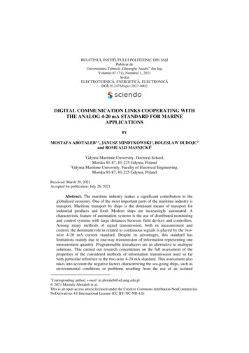
Bul. Inst. Polit. Iaşi, Vol. 67 (71), Nr. 1, 2021273.1.2. Foundation FieldbusFoundation Fieldbus (FF) IEC 61158 relies basically on the idea ofusing a single twisted pair of wires for connection of field devices. The role offield devices in the network is extended beyond the regular role of measuringprocess variables, as they will have the capability of performing manyautomation tasks. Foundation Fieldbus can also provide reliable measurementand control operations in hazardous application areas. It is a completely digitalcommunication protocol which replaces 4-20 mA current signal with digitaltransmission of Manchester coded signal which includes measurement andcontrol information as well as additional diagnostic, parameterization and faultdetection information (Liptak, 2006). This additional information provided byFoundation Fieldbus is extensively more advanced than same type ofinformation provided by HART (Liptak, 2012; Mackay et al., 2003; Mehta andReddy, 2015; Verhappen and Pereira, 2012).Fig. 4 – Manchester coding in Foundation Fieldbus.Manchester coding is a modulation technique that depends on a basecurrent signal of 10 mA (Fig. 4). Current will rise from 10 mA to 19 mA in caseof logic “0” or will fall from 10 mA to 1 mA in case of logic “1”. These currenttransitions are synchronized with the system clock. The advantage of usingFieldbus devices is that loop current can be used for power supplying fielddevices, and the transmitted signal will never fall to the zero level. Therefore,any failure through the fieldbus can be easily detected (Liptak, 2012; Mackay etal., 2003; Mehta and Reddy, 2015; Verhappen and Pereira, 2012).
28Mostafa Abotaleb et al.Foundation Fieldbus uses two types of buses. First bus is relativelyslow H1 (Manchester Coded Data) with a rate of 31.25 kbps, and the secondone is a faster bus HSE (High Speed Ethernet) with a rate of 1 to 2.5 Mbps.H1 bus is used to connect all field devices to a single twisted pair of wiresthrough spurs with a maximum length of 120 m/spur. Voltage across terminalsof the field device should be at least 9 VDC and not more than 32 VDC(nominally 24 VDC) to ensure proper communication conditions along thefield bus(Liptak, 2012; Mackay et al., 2003; Mehta and Reddy, 2015;Verhappen and Pereira, 2012).Protocol FF adopts a distributed communication system with a networkaccess through a deterministic, centralized management system in which LAS(Link Active Scheduler) undertakes the role of controlling and supervising thescheduled and unscheduled communication process. UnscheduledCommunication is used for transaction of diagnostic data and field devicesparameters. It takes place during breaks between scheduled communicationintervals. Scheduled Communication can be divided into two categories, thefirst one is related to control and measurement variables, while the second oneis related to system management (Liptak, 2012; Mackay et al., 2003; Mehta andReddy, 2015; Verhappen and Pereira, 2012).3.1.3. ProfibusThere are three variants of PROFIBUS communication protocol:1- Profibus FMS (Fieldbus Message Specification);2- Profibus DP (Decentralized Periphery);3- Profibus PA (Process Automation).Profibus FMS supports communication between automation stationsand programmable logic controllers with an average speed. Profibus DP mainadvantage is its speed and suitability for applications that requires fast response(data rate of 9.6 kbps to 12 Mbps). It allows for communication betweenautomation stations and field devices. Class-1 master and Class-2 master aretwo types of masters which are available in Profibus DP. Class-1 master isresponsible for cyclic data exchange between field devices and automationstation in a specific cycle time. Class-2 master is responsible for monitoring,visualization and parameterization by data exchange with field devices in anacyclic manner. These acyclic services (Alarms, Alerts and parameters) wereintroduced in the extended variant Profibus DPV1 (Liptak, 2012; Mehta andReddy, 2015; Felser, 2017; PI, 2016).Profibus PA was designed for field devices in process automation.A Profibus PA network consists of DPM1 (Class-1 Master), DPM2 (Class-2Master), and slave field devices. DPM1 is responsible of cyclic data exchangeof information such as measured values, set points and status conditions. DPM2is responsible of acyclic data exchange of information required during operation
Bul. Inst. Polit. Iaşi, Vol. 67 (71), Nr. 1, 202129and monitoring. Slave field devices are either transmitters or actuators. Theycan communicate with either of these two masters only upon master’s request(Liptak, 2012; Mehta and Reddy, 2015; Felser, 2017; PI, 2016).Transmission technique in Profibus can be either RS485 with a rate of9.6 to 12 Mbps (Profibus DP), or IEC61158-2 with a bit rate of 31.25 kbps(Profibus PA). RS485 or RS485(IS) interfaces are adopted as a transmissiontechnology by Profibus DP, while MBP (Manchester Bus Powered) is adoptedas a transmission technology by Profibus PA (Liptak, 2012; Mehta and Reddy,2015; Felser, 2017; PI, 2016).Profibus network field devices can be assigned addresses from 0 to 127.Addresses are assigned to field devices through token passing and Master/Slavecommunication (Fig. 5) similarly to Foundation Fieldbus. Address 126 isreserved for automatic address assignment via the master to newly installedfield devices. Address 127 is assigned for telegram broadcasting to all fielddevices. Address 0 is usually assigned to class-1 master and addresses from 1 to125 are usually assigned to class-2 master and rest of other field devices,respectively (Felser, 2017).Fig. 5 – Profibus Master / Slave and Pass Token Communication.Field devices are integrated into Profibus network through four differentstandards dedicated for such a purpose (Liptak, 2012; Mehta and Reddy, 2015;Felser, 2017; PI, 2016): General Station Descriptions (GSD). Electronic Device Description (EDD). Device Type manager (DTM) and Field Device Tool (FDT). Tool Calling Interface (TCI).3.1.4. ModbusBasic Modbus is aMaster/Slave (M/S) bus serial communicationprotocol through which a single master can communicate with up to 247 slave
30Mostafa Abotaleb et al.devices connected to the same bus. The master can communicate with only oneslave device, or it can communicate with all slave devices through a broadcasttransmission. Slave devices respond to master queries by response with therequested data only in case of communicating with one slave device, however incase of broadcast communication no response messages are provided by any ofthe slave devices (Modbus IDA, 20.12.2006; Modbus IDA, 28.12.2006).There are many versions of Modbus protocol, among of which there arethree versions that are the most widely used. The first two versions use the M/Sas a media access control method, and the third one uses CSMA/CD method: Modbus RTU, Modbus ASCII, Modbus TCP/IP.Modbus RTU (Remote Terminal Unit) is the most popular version ofModbus protocol in industrial automation as it uses CRC (Cyclic RedundancyCheck) error checking mechanism which is more powerful than the mechanismLRC (Longitudinal Redundancy Check) used with Modbus ASCII. ModbusRTU uses binary coding for transmitted data while Modbus ASCII uses ASCIIcoding. Modbus RTU communication frame consists of 11 bits: a start bit, 8data bits, parity bit and one stop bit. In case no parity condition was used, therewill be 2 stop bits instead of one. The Modbus message consists of sequence ofcommunication frames making up individual fields. In Modbus RTU, messageframe (Fig. 6) consists of slave address, function code, up to 252 bytes andfinally two CRC bytes. These frames are sent with separation intervals of atleast 3.5 silent characters (Liptak, 2012; Mehta and Reddy, 2015; Modbus IDA,20.12.2006; Modbus IDA, 28.12.2006).In Modbus ASCII, each communication frame consists of 10 bits, astart bit, 7 data bits, a parity bit and a stop bit. In case no parity was considered,there will be 2 stop bits. As for Modbus RTU, the Modbus ASCII messageframe (Fig. 9) consists of sequence of communication frames. The ModbusASCII message frame consists of frame start (colon character ":"), slave address(2 ASCII characters), function (2 characters), data (up to 252 characters),longitudinal redundancy check (2 characters) and end of the frame (carriagereturn, line feed "CR, LF" characters) (Modbus IDA, 20.12.2006; Modbus IDA,28.12.2006).Despite differences between Modbus RTU and Modbus ASCII, both ofthem are serial communication protocols which share the same physical layerthat might be any of serial interfaces which will be discussed later in this articleRS232, RS422 and RS485 (Liptak, 2012; Mehta and Reddy, 2015; ModbusIDA, 20.12.2006; Modbus IDA, 28.12.2006).
Bul. Inst. Polit. Iaşi, Vol. 67 (71), Nr. 1, 202131Fig. 6 – The message frame structures in Modbus different versions.Unlike Modbus RTU and Modbus ASCII protocols, Modbus TCP/IP isa client/server protocol. Instead of addresses assigned to devices connected tothe serial communication bus, Modbus TCP/IP identifies the devices in thenetwork by their IP addresses. In Modbus TCP/IP, devices are connectedthrough an Ethernet interface. In Modbus TCP/IP message frame, the ModbusApplication Header (MBAP) (Fig. 6) replaces the slave address as well as thefunction and the redundancy check characters are removed. MBAP headercontains all the required information to send the data to the addressed device(Liptak, 2012; Mehta and Reddy, 2015; Modbus IDA, 20.12.2006; ModbusIDA, 28.12.2006).3.2. Communication Interfaces Responsible for Serial Communication BetweenAutomation Stations and Input/Output Modules3.2.1. RS232 Serial InterfaceControlled by a specific protocol, RS232 is a point to pointcommunication interface which allows only for two devices. In RS232, data isrepresented in negative logic. Control signals are represented in positive logic.For negative logic, the voltage level of logic 0 is between 3VDC and 15VDC,while voltage level for logic 1 is between -15VDC and -3 VDC (Fig. 7) andvice versa for positive logic (Mackay et al., 2003; Mehta and Reddy, 2015;Sonnenberg, 2018).Fig. 7 – RS232 Unbalanced Voltage Signal Level.
32Mostafa Abotaleb et al.Data is transmitted asynchronously with a baud rate between 50 and115 kbps. RS232 data are formatted as UART communication frames with startbit, data bits, parity bit and stop bit or bits. The voltage level of an idle RS232bus is a negative voltage (regularly -12 VDC) (logic 1). At the beginning oftransmission, transmitter sends a start bit (logic 0). Receiver will synchronizewith the transmitter by the start bit and by the identical baud rate preset at bothof transmitter and receiver sides. Data bits are sent after start bit with LSBfirstly transmitted (Mackay et al., 2003; Mehta and Reddy, 2015; Sonnenberg,2018).3.2.2. RS422 Serial InterfaceRS422 interface provides faster data transmission over longer distancesthan RS232. It allows for maximum number of 10 receivers to be connected inparallel with a single transmitter. Maximum allowable cable length is dependentof used data rate. For a data rate of 100 kbps, transmission line can have amaximum length of 1200 m, while for a data rate of 10 Mbps transmission linecan have a maximum length of 15 m. RS422 interface is a balanced to groundinterface. RS422 transmitter has a signal with a voltage level of 2 to 6 VDC toexpress about logic 0, and a voltage signal level from -2 to -6 VDC to expressabout logic 1. For logic 0 at the receiver side, the lower limit of the detecteddifferential voltage will be 200 mV, and the upper limit will remain 6 VDC. Forlogic 1 at the receiver side, the lower limit of the detected differential voltagewill be -6 VDC, and the higher limit will be -200 mV (Fig. 8) (Mackay et al.,2003; Mehta and Reddy, 2015; Marais, 2008; Sonnenberg, 2018).Fig. 8 – RS422 Balanced Voltage Signal Level.In RS422 interface, transceiver can tolerate a common mode voltage upto /-7VDC. Transmitters in RS422 interface should be able to withstand thecommon mode voltage when they are in the idle state. Receiver inputimpedance should be equal to or greater than 4 kΩ. Termination resistors shouldbe connected at the end of the transmission line, their values should be equalto the characteristic impedance of the transmission line (Marais, 2008; Mackayet al., 2003; Mehta and Reddy, 2015).
Bul. Inst. Polit. Iaşi, Vol. 67 (71), Nr. 1, 2021333.2.3. RS485 Serial InterfaceRS485 interface allows for up to 32 devices in half duplex or fullduplex communication mode. Spacing between devices should be consideredcarefully to avoid impedance mismatch (Gingerich, 2006). Similarly, to RS422interface, RS485 interface can have a maximum cable length of 15 or 1200 m,respectively corresponding to the data rates of 100 kbps and 10 Mbps. Signaldifferential voltage level for logic 0 is from 1.5 to 5 VDC and from -5 to -1.5VDC for logic 1. RS485 drivers should be able to withstand a common modevoltage from -7 to 12 VDC (Fig. 9). Input impedance of RS485 receivershould be equal to or higher than 12 kΩ (Marais, 2008; Mackay et al., 2003;Mehta and Reddy, 2015; Sonnenberg, 2018).RS485 interface usually includes distant nodes supplied by differentpower supply units. Therefore, there will be usually a Ground PotentialDifference (GPD) between different nodes, which leads to ground current loops.In order to avoid formation of ground loops, supply isolators and signalisolators are recommended to be used with RS485 transceivers (Kugelstadt,2008).Fig. 9 – RS485 Balanced Voltage Signal Level.Power source fluctuations, electrostatic discharge and inductiveswitching, any of them might be a possible cause for high levels of transientvoltages which might damage RS485 transceivers. TVS diodes are used toprotect transceivers by limiting spike voltages. When transient voltage is greaterthan TVS diode breakdown voltage, TVS diode resistance will decrease tomaintain the common mode voltage at levels from -7 to 12 VDC (Marais,2008).4. Experimental Research4.1. Laboratory Stand and Conducted Case StudiesAn experimental research was conducted in the laboratory of theGdynia Maritime University. It focuses on testing the 4-20 mA current loop,examined under simulated conditions. The purpose of these experiments was to
34Mostafa Abotaleb et al.verify the performance difference between a classical 4-20 mA measurementcurrent loop and a smart 4-20 mA measurement current loop (HARTTransmitter was used in a smart measurement loop). The sensitivity of a HARTtransmitter to various sources of noise was a major point of interest incomparison with a classical 4-20 mA transmitter. The way of connecting thecable shield and the way of grounding various power sources are factors thatcan lead to the formation of ground loops and consequently inflect a negativeinfluence on the measurement process. The possibility of physical connectionbetween the shield terminal and a cable terminal due to conditions such as lowinsulation in junction boxes caused by humidity, corrosion and vibration arealso factors that was taken into account in this experimental approach.Fig. 10 – Initial Connection of 4-20 mA measurement loop at the laboratory stand.As illustrated in Fig. 10, the current loop consists of HART smartTransmitter (Rosemount HART Temperature Transmitter 3244MV), 10 meterslong of shielded twisted pair cable, DC power supply of 24 VDC, 250 Ωresistance and an ammeter to measure the current flowing in the loop.Additionally, two types of HART hand held communicators will beconnected across the transmitter terminals to assess the HART communicationsignal of both communicators and also for comparison between both of them. Emerson AMS Trex Device Communicator. Emerson 375 Field Communicator.The HART communication signal of each of the 2 hand heldcommunicators will be displayed on an oscilloscope through a voltage probeconnected across the two terminals of HART temperature transmitter.
Bul. Inst. Polit. Iaşi, Vol. 67 (71), Nr. 1, 202135Grounding of devices of which a 4-20 mA current loop is composed, isa very important issue to consider. Generally, it is recommended for thegrounding point at the transmitter side to be connected to the shield of the cableonly from the transmitter side and the other side of the cable shield should betapped and isolated in order to avoid formation of ground loops due to differentpotential values. This applies for both of classical 4-20 mA transmitters and alsosmart transmitters. Accordingly, and in order to test the negative effects causedby low insulation or improper grounding mechanisms (Induced by manycauses) in the measurement 4-20 mA current loop: Resistor RE is connected between the grounding point of thetransmitter and the earth. Switches S2 and S3 are used to connect the shield to variousgrounding points. Switch S4 connecting the earth point to the grounding pointof the DC power supply. Switch S5 is used to simulate a fault condition where the shield canbe connected to one of the two wires outgoing from the transmitter. Resistance RT is connected to the HART temperature transmitter forsimulatingachange in resistance corresponding to the temperature change.Resistance RT was adjusted to simulate a random measured temperatureof 44.35 which is converted to a loop current of 15.61 mA (measured as15.55 mA by hand held communicators).An experimental research was conducted
communication in ship automation systems will be presented. Firstly, description will be provided for HART protocol (Highway Addressable Remote Transducer), Foundation Fieldbus, Profibus PA and Modbus as communication protocols adopted by modern smart transducers as alternatives for classical analogue 420 mA transducers.