Transcription
Reference Manual00809-0200-4420, Rev HESeptember 2020Emerson Wireless 1420 Gateway
Safety MessagesNOTICERead this manual before working with the product. For personal and system safety, and for optimum product performance, makesure you thoroughly understand the Contents before installing, using, or maintaining this product.WARNINGFailure to follow these installation guidelines could result in death or serious injury.Ensure only qualified personnel perform the installation.Explosions could result in death or serious injury.Verify that the operating atmosphere of the transmitter is consistent with the appropriate hazardous locations certifications.Electrical shock could cause death or serious injury.If the device is installed in a high-voltage environment and a fault condition or installation error occurs, high voltage may bepresent on transmitter leads and terminals.Use extreme caution when making contact with the leads and terminals.This device complies with Part 15 of the FCC Rules. Operation is subject to the following conditions:This device may not cause harmful interference.This device must accept any interference received, including interference that may cause undesired operation.This device must be installed to ensure a minimum antenna separation distance of 20 cm from all persons.The products described in this document are NOT designed for nuclear-qualified applications. Using non-nuclear qualifiedproducts in applications that require nuclear-qualified hardware or products may cause inaccurate readings.For information onRosemount nuclear-qualified products, contact your local Emerson Sales Representative.2
Reference Manual00809-0200-4420ContentsSeptember 2020ContentsChapter 1Introduction. 51.1 Product overview.51.2 Using this manual. 51.3 Product recycling/disposal.6Chapter 2Configuration. 72.1 Overview. 72.2 System requirements.72.3 Initial setup. 7Chapter 3Installation.173.1 Overview. 173.2 Mounting.173.3 Remote antenna (optional).193.4 Connecting.23Chapter 4Commissioning . 354.1 Overview. 354.2 System requirements.354.3 Software installation. 364.4 Security Setup Utility. 364.5 AMS Wireless Configurator. 384.6 Licensing and credits. 40Chapter 5Operation and Maintenance. 435.1 Overview. 435.2 Network architecture.435.3 Internal firewall.465.4 Modbus. 475.5 EtherNet/IP. 53Chapter 6Troubleshooting. 576.1 Service support.576.2 Troubleshooting Tables. 576.3 Return of materials. 61Chapter 7Appendix AGlossary. 63Specifications and Reference Data. 65A.1 Functional specifications. 65A.2 Physical specifications. 66A.3 Communication specifications. 67Emerson.com/Rosemount3
ContentsSeptember 2020Reference Manual00809-0200-4420A.4 Self-organizing network specifications. 68A.5 System security specifications. 68A.6 Dimensional drawings. 70A.7 Ordering information. 72A.8 Accessories and spare parts. 73Appendix BProduct Certifications. 75B.1 European directive information. 75B.2 Telecommunication Compliance. 75B.3 FCC and IC. 75B.4 Ordinary location certification .75B.5 Installing Equipment in North America.75B.6 USA.75B.7 Canada. 76B.8 Europe. 76B.9 International.77B.10 Brazil.77B.11 China. 78B.12 Japan. 78B.13 EAC – Belarus, Kazakhstan, Russia.78B.14 Combination.78Appendix CDeltaV Ready. 79C.1 Overview. 79C.2 Latency considerations in control logic design and operation. 79C.3 Requirements.79C.4 Mounting and connecting. 79C.5 Setup.80Appendix DRedundancy. 85D.1 Overview.85D.2 Requirements.85D.3 Setup redundant gateways.85D.4 Mounting and connections.88D.5 Diagnostics. 92D.6 Gateway replacement. 944Emerson.com/Rosemount
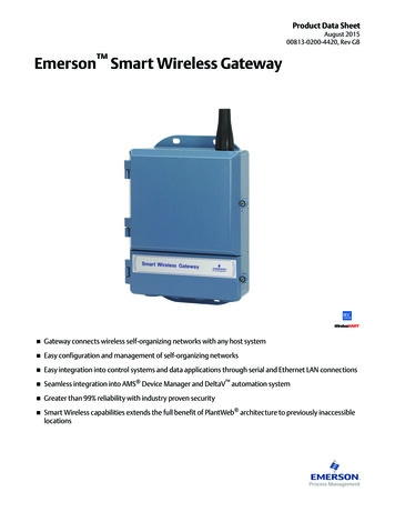
Reference Manual00809-0200-4420IntroductionSeptember 20201Introduction1.1Product overviewThe Emerson Wireless 1420 Gateway (Gateway) connects WirelessHART self-organizingnetworks with host systems and data applications. Modbus communications over RS-485or Ethernet LAN provide universal integration and system interoperability. The optionalOPC functionality from the Gateway offers a means to connect to newer systems andapplications while providing a richer set of data.The Gateway provides industry leading security, scalability, and data reliability. Layeredsecurity ensures that the network stays protected. Additional devices can be added atanytime. There is no need to configure communication paths because the Gatewaymanages the network automatically. This feature also ensures that WirelessHART fielddevices have the most reliable path to send data.What is included?The box containing the Gateway contains several items essential to the completeinstallation and operation of the Gateway. Emerson Wireless 1420 Gateway Quick Start Guide Software pack, 2-disk set Mounting hardware Conduit plugs, four Conduit adapters (optional)If an optional remote antenna has been ordered, it will be in a separate box containing: Remote mount antenna Mounting hardware Lightning arrestor Cable (one or two pieces that total 50 ft. [15,2 m] in length) Coaxial sealant1.2Using this manualThis manual will help to install, configure, operate, and maintain the Gateway.Introduction introduces the product and describes what components may be found in thebox. It also includes details for services and support as well as return and disposal of theproduct.Configuration describes how to connect to the Gateway for the first time and whatsettings should be configured before placing it on a live control network. It is important toEmerson.com/Rosemount5
IntroductionSeptember 2020Reference Manual00809-0200-4420note that some Gateways are used in stand-alone applications and do not reside on anetwork. In these cases, it is still important to configure the items outlined in this section.Installation describes how to properly mount the Gateway and make electricalconnections, including electrical wiring, grounding, and host system connections. Thissection also describes how to mount the optional remote antenna.Commissioning describes the installation and setup of the optional software included withthe Wireless Gateway. This software will aid in secure host integration as well as wirelessfield device configuration.Operation and Maintenance describes how to connect the Gateway to a host system andintegrate data gathered from the field device network. It covers network architectures,security, and data mapping.Troubleshooting provides troubleshooting tips as well as information to contact technicalsupport over the phone or through email.Glossary defines terms used throughout this manual or that appear in the web interface ofthe Wireless Gateway.Appendices provide additional and more specific information on a variety of subjectsincluding Specifications and Reference Data and Product Certifications.1.3Product recycling/disposalConsider recycling equipment and packaging. Dispose of the product and packaging inaccordance with local and national legislation.6Emerson.com/Rosemount
Reference Manual00809-0200-4420ConfigurationSeptember 20202Configuration2.1OverviewThis section describes how to connect to the Emerson Wireless 1420 Gateway (Gateway)for the first time and what settings should be configured before placing it on a live controlnetwork. It is important to note that some Gateways are used in stand-alone applicationsand do not reside on a network. In these cases, it is still important to configure the itemsoutlined in this section.Before the Gateway can be permanently mounted and connected to a live controlnetwork, it needs to be configured with an IP address. This is done by forming a privatenetwork between the gateway and a PC/laptop. The following items are needed tocomplete this section: Gateway PC/laptop 24 VDC (nominal) power supplyNote If the Gateway was ordered with the DeltaV Ready option, it has been configured tooperate on a DeltaV control network, and the Initial Configuration Section does not needto be completed. Only setting the password is required.2.2System requirementsThe following requirements apply to the PC/laptop used to configure the Gateway.Additional requirements may apply if using the optional Security Setup Utility or AMSWireless Configurator. See Commissioning for more information.Web browser applications Mozilla Firefox 1.5 or higher Microsoft Internet Explorer 7.0 or higherEthernet 10/100BaseTX Ethernet communication protocol2.3Initial setupNoteFor information on connecting a Windows 7 PC, see the technical note (documentnumber 00840-0900-4420).Emerson.com/Rosemount7
ConfigurationSeptember 20202.3.1Reference Manual00809-0200-4420Prepare PC/laptopThe PC/laptop will need to be configured to form a private network before communicatingto the Gateway. The network settings can be found in the control panel of the PC/laptop.To configure these settings:Procedure1. Find and open the Control Panel (Generally found from the Start Menu).2. Open Network Connections.3. Select Local Area Connection or Network and Sharing Center.4. Right click the mouse and select Properties from the list.5. Select Internet Protocol (TCP/IP), then select Properties.6. From the General tab, select Use the following IP address.7. Set the IP Address to “192.168.1.12” and select Tab.8. A Subnet mask of 255.255.255.0 should fill in automatically.9. Select OK to close the Internet Protocol (TCP/IP) window.10. Select Close on the Local Area Connection window.2.3.2Disable Internet proxiesInternet proxies will need to be disabled through the PC/laptop’s default Internet browser.Procedure1. Find and open the default internet browser (typically Microsoft Internet Explorer).2. From the Tools menu, select Internet Options.3. From the Connections tab, select LAN Settings.4. Under Proxy Server, verify the boxes for Automatically Detect Settings and Use aproxy server for your LAN are unchecked.5. Select OK to close the Local Area Network (LAN) Settings window.6. Select OK to close the Internet Options window.ExampleThe PC/laptop is now set up to form a private network and to communicate with theGateway.NoteConnecting to the Gateway's secondary Ethernet port will require different networksettings. See Table 2-1 for additional network settings.Table 2-1: Default IP Addresses8GatewayPC/laptopSubnetEthernet 1192.168.1.10192.168.1.12255.255.255.0Ethernet 2192.168.2.10192.168.2.12255.255.255.0Ethernet 1 (DeltaV om/Rosemount
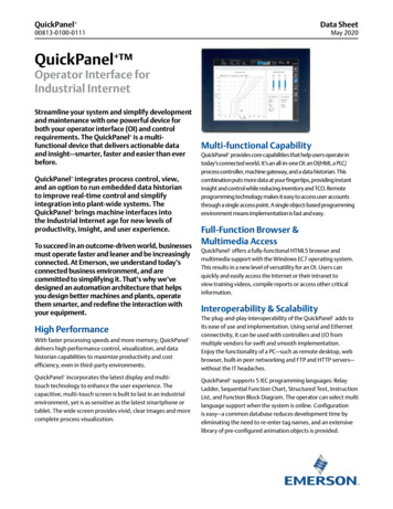
Reference Manual00809-0200-4420ConfigurationSeptember 2020Table 2-1: Default IP Addresses (continued)Ethernet 2 (DeltaV 255.200255.254.0.0Connections and powerPhysically connect the PC/laptop to the Gateway by connecting one end to the Ethernetport on the back of the PC/laptop. Connect the other end to the Ethernet 1 port on theGateway. Figure 2-1 shows the standard terminal block diagram. Once the Gateway andPC/laptop are connected, wire a 24 VDC (nominal) power supply with a capacity of at least250 mA to the Gateway power input terminals.Determining Gateway compatibility with Power overEthernet (PoE)Figure 2-1: Legacy Gateway Terminal BlockE F-SAGGB -SS-SS- - A et 2 with power (covered)Ethernet 2 (secondary)Ethernet 1 (primary)24 VDC (nominal) power inputSerial Modbus Not used9
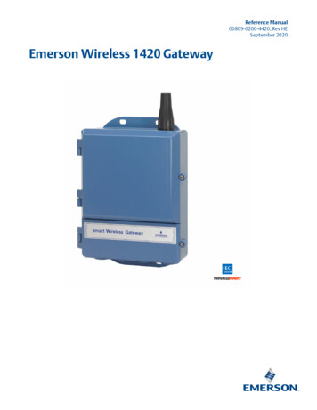
ConfigurationSeptember 2020Reference Manual00809-0200-4420Figure 2-2: PoE Compatible Gateway Terminal BlockD E-SAA.B.C.D.E.ABBCCaseEthernet 2 (secondary)Ethernet 1 (primary)24 VDC (nominal) power inputSerial ModbusWARNINGWhen making physical connections to the Gateway it is important to use the electricalconduit entries located on the bottom of the housing. Connecting through the openterminal block cover (the lower cover) may stress the connections and damage theGateway.Power over EthernetThis Gateway is equipped with PoE technology to allow it to source power to a compatibledevice over the connecting Ethernet cable (PSE mode) or derive its power from anotherPoE device via the Ethernet connection (PD mode). This device complies with the IEEE802.3at-2009 standard for PSE operation and IEEE 802.3af-2003 or IEEE 802.3at -2009 forPD operation. These standards require the use of Category 5 Ethernet cable or higher.In the operation of IEEE 802.3a, PoE power is only transmitted from one device to anotherwhen the proper impedance match is made. This prevents damage to non PoE devices onthe network. In the Gateway, power is transmitted in passive mode over two unuseddifferential pairs of the Ethernet cable. To use this feature, the Gateway must beconnected over the Ethernet to a matching IEEE 802.3a device. Failure to do this will causeno power to be sent or sourced.A set of switches on the power supply board allow the selection of the specific Ethernetport for PoE and the selection of whether it is a PSE (Power Sourcing Equipment) sourcingpower or a PD (Powered Device) deriving its power from another IEEE 802.9 PSE device.See Figure 2-3 for the switch diagram required for PoE configuration.NoteThe Gateway can either source or receive power over an Ethernet port; it cannot do bothat the same time.If using the Gateway as a PSE, the total additional power requirements of the PD must befactored into the total input power requirements of the power supply for the Gateway. It is10Emerson.com/Rosemount
Reference Manual00809-0200-4420ConfigurationSeptember 2020recommended that the power selection mode switch be left in the PD position unless PSEis needed.Figure 2-3: Gateway PoE JumperingETH1ETH2PSEInput Power10.5V-30VSCaseModbusABPD PSEENDISEthernet 2PD PSEETH1ETH2PSEInput Power10.5V-30VSCaseAFrom PSE DeviceDataETH1ETH2ModbusSABTo HostENDISEthernet 2PD PSETo HostPowerInput Power10.5V-30VPSECasePD PSEEthernet 1BENDISPD PSETo HostModbusEthernet 2PD PSEEthernet 1PowerEthernet 1PowerTo POE DevicePowerDataTraditionally powered GatewayPoE, Gateway as a PD via Ethernet Port 2PoE, Gateway as a PSE via Ethernet Port 2 ETH1: Ethernet port 1 selected for PD or PSE ETH2: Ethernet port 2 selected for PD or PSE PD: Gateway derives power from the Ethernet port selected PSE: Gateway derives power from a local power supply and sends power down theEthernet port selected to another device EN: Enabled; this enables the PSE operation DIS: Disabled; this disables the PSE operationNoteOnly one port and one mode of operation (PD or PSE) can be selected at a time; any othercombination of jumpers is invalid.NoteIEEE 802.3af-2003 PoE standard provides up to 15.4 W of DC power (minimum 44 V DCand 350 mA) to each device. Only 12.95 W is assured to be available at the powered deviceas some power is dissipated in the cable. IEEE 802.3at-2009 PoE standard also known as“PoE ” or “PoE plus”, provides up to 25.5 W of power. The 2009 standard prohibits apowered device from using all four pairs for power.For more information on PoE and frequently asked questions, refer to Emerson Wireless1420 Gateway with Power over Ethernet Technical Note or Power over Ethernet (PoE).In order to use both ports for PoE, remember to order option code “2” when selectingnumber of Ethernet ports.Emerson.com/Rosemount11
ConfigurationSeptember 20202.3.4Reference Manual00809-0200-4420Configure the GatewayIt is now possible to log into the Gateway for the first time and begin configuration forplacement on a live control network. The following items need to be configured: Security passwords Time settings TCP/IP network settingsUse the following procedure to log in to the Gateway:Procedure1. Open a standard web browser (typically Microsoft Internet Explorer).2. Enter “192.168.1.10” in the address bar.3. Acknowledge the security to proceed.4. In the User Name field, enter “admin”.5. In the Password field, enter “default”.ExampleThe web browser will now be directed to the Gateway’s default home page. There is anavigation menu located on the left hand side with four main areas. Diagnostics: view status of communications, client server parameters, and more Monitor: screens created by the user to view data from field devices Explorer: basic view of values from field devices Setup: configure the Gateway for operations, security, and host system integrationSecurity passwordsThere are four-role based user accounts for the Gateway with varying levels of access. Thetable below describes this access.Table 2-2: Role Based Access User AccountsRoleUser nameWeb interface accessExecutiveexecRead-only accessOperatoroperRead-only accessMaintenancemaintConfigure HART device settingsConfigure Modbus communicationsConfigure Modbus register mappingConfigure OPC browse treeConfigure Active Advertising12Emerson.com/Rosemount
Reference Manual00809-0200-4420ConfigurationSeptember 2020Table 2-2: Role Based Access User Accounts (continued)RoleUser nameWeb interface accessAdministratoradminIncludes all maintenance privilegesConfigure Ethernet network settingsConfigure WirelessHART network settingsSet passwordsSet time settingsSet home page optionsConfigure custom point pagesRestart applicationsEach of the initial passwords for the user accounts is default. It is recommended, forsecurity purposes, that these passwords are changed. The administrator password shouldbe appropriately noted when changed. If it is lost, contact Emerson for technical support.To change the user accounts passwords:Procedure1. Navigate to System Settings Users User options.2. Click Edit.3. Set the new password for each role based user account, and confirm.4. Click Submit.NoteIt is suggested that the default security settings in System Settings Users Useroptions be changed to the local IT best practices or the Normal setting after initiallogin. Strong or custom settings are available for more robust passwords. For moreinformation on this screen and others, see the Emerson Wireless Gateway UserInterface Terminology Guide.Time settingsThe Gateway is the timekeeper for the WirelessHART network, so it is imperative that theGateway’s time is accurate for timestamp data to be meaningful. Time settings can befound by navigating to System Settings Gateway Time.There are three ways to set the Gateway time: Network Time Protocol (recommended)— This option uses a Network Time Protocol (NTP) server to adjust the Gateway’s timein order to match the time of the control network. Enter the IP address for the NTPserver and select the packet version (1, 2, 3, or 4). Set with PC Time— This option will match the Gateway’s time to that of the PC/laptop. Manual Entry— This option allows the user to enter a specific date (MM:DD:YY) and time(HH:MM:SS).Emerson.com/Rosemount13
ConfigurationSeptember 2020Reference Manual00809-0200-4420NoteNetwork Time Protocol (NTP) is recommended for the best network performance becauseit always adjusts time to match the network time server.Figure 2-4: Time SettingsTCP/IP network settingsWARNINGUse caution when making changes to the TCP/IP network settings. If they are lost orimproperly configured, it may be impossible to log into the Gateway. Contact the networkadministrator for information on the proper TCP/IP network settings to apply.Prior to the gateway being installed and connected to a live control network, it should beconfigured with an IP address, as well as other TCP/IP network settings.Request the following configuration items from the network administrator: Specify an IP address, or use a DHCP server Hostname Domain Name IP address Netmask Gateway14Emerson.com/Rosemount
Reference Manual00809-0200-4420ConfigurationSeptember 2020Obtaining an IP address from a DHCP server is not recommended, since the Gatewayoperation will be dependent upon the availability of the DHCP server. For maximumgateway availability it is best practice to specify an IP address.To change the TCP/IP Network Settings:Procedure1. Navigate to System Settings Gateway Ethernet Communication.2. Select Specify an IP address (recommended).3. Enter the following: Hostname Domain Name IP Address Netmask Gateway4. Select Save Changes.5. When prompted, select Restart apps.6. Select Yes to confirm restart.7. Close the web browser.NoteOnce the IP Address of the Gateway has been changed, communications to the webinterface will be lost. Restart the web browser, then log back into the Gateway usingthe new IP address and other TCP/IP network settings. The PC/laptop TCP/IPnetwork settings may need to be changed.Emerson.com/Rosemount15
ConfigurationSeptember 2020Reference Manual00809-0200-4420Figure 2-5: Ethernet Settings2.3.5System backupThe Gateway has a System Backup and Restore feature that saves all user-configured data.It is best practice that a System Backup be performed periodically throughout theinstallation and configuration process.Procedure1. Navigate to System Settings Gateway Backup And Restore.2. Select Save Backup.3. The Gateway collects the configuration date and when the file download pop upappears, select Save.4. Enter a save location and file name.5. Select Save.6. Select Return to form.NoteSystem backup contains user passwords and keys used for encryptingcommunication. Store downloaded system backups in a secure location. These filesthemselves are also encrypted.16Emerson.com/Rosemount
Reference Manual00809-0200-4420InstallationSeptember 20203Installation3.1Overview This section describes how to properly mount the Emerson Wireless 1420 Gateway(Gateway) and make electrical connections, including electrical wiring, grounding, andhost system connections. This section also describes how to mount the optional remoteantenna.3.1.1General considerationsThe Gateway may be mounted in any general purpose location. Be sure the covers aresecured tightly to prevent exposure of any electronics to moisture and contamination.The Gateway should be mounted in a location that allows convenient access to the hostsystem network (process control network) as well as the wireless field device network.3.1.2Physical descriptionFor dimensional drawing information refer to Product Certifications. The cast aluminumhousing encloses the electronics circuitry of the Gateway. The front of the enclosure hasan upper cover and a junction box cover. The upper cover provides access to theelectronics and radio. The junction box cover provides access to the terminal block.To open either cover, use a 1/4-in. bladed screwdriver to remove the appropriate screw
security, and data mapping. Troubleshooting provides troubleshooting tips as well as information to contact technical support over the phone or through email. Glossary defines terms used throughout this manual or that appear in the web interface of the Wireless Gateway. Appendices provide additional and more specific information on a variety of .