Transcription
NSS evo3Installation ManualENGLISHwww.simrad-yachting.com
PrefaceDisclaimerAs Navico is continuously improving this product, we retain the right to make changes to theproduct at any time which may not be reflected in this version of the manual. Please contactyour nearest distributor if you require any further assistance.It is the owner’s sole responsibility to install and use the equipment in a manner that will notcause accidents, personal injury or property damage. The user of this product is solelyresponsible for observing safe boating practices.NAVICO HOLDING AS AND ITS SUBSIDIARIES, BRANCHES AND AFFILIATES DISCLAIM ALLLIABILITY FOR ANY USE OF THIS PRODUCT IN A WAY THAT MAY CAUSE ACCIDENTS, DAMAGEOR THAT MAY VIOLATE THE LAW.Governing Language: This statement, any instruction manuals, user guides and otherinformation relating to the product (Documentation) may be translated to, or has beentranslated from, another language (Translation). In the event of any conflict between anyTranslation of the Documentation, the English language version of the Documentation willbe the official version of the Documentation.This manual represents the product as at the time of printing. Navico Holding AS and itssubsidiaries, branches and affiliates reserve the right to make changes to specificationswithout notice.CopyrightCopyright 2016 Navico Holding AS.WarrantyThe warranty card is supplied as a separate document.In case of any queries, refer to the brand website of your unit or system: www.simradyachting.com.Compliance statementsThis equipment complies with: CE under 2014/53/EU Directive The requirements of level 2 devices of the Radio communications (ElectromagneticCompatibility) standard 2008 Part 15 of the FCC Rules. Operation is subject to the following two conditions: (1) thisdevice may not cause harmful interference, and (2) this device must accept anyinterference received, including interference that may cause undesired operation.The relevant Declaration of conformity is available in the product's section at the followingwebsite: www.simrad-yachting.com.Industry CanadaIC RSS-GEN, Sec 7.1.3 Warning Statement- (Required for license exempt devices)This device complies with Industry Canada license-exempt RSS standard(s). Operation issubject to the following two conditions: (1) this device may not cause interference, and (2)this device must accept any interference, including interference that may cause undesiredoperation of the device.Le présent appareil est conforme aux CNR d’IndustrieCanada applicables aux appareils radio exempts de licence. L’exploitation est autorisée auxdeux conditions suivantes: (1) l’appareil ne doit pas produire de brouillage, et (2) l’utilisateurde l’appareil doit accepter tout brouillage radioélectrique subi, même si le brouillage estsusceptible d’en compromettre le fonctionnement.WarningThe user is cautioned that any changes or modifications not expressly approved by the partyresponsible for compliance could void the user’s authority to operate the equipment.Preface NSS evo3 Installation Manual3
This equipment generates, uses and can radiate radio frequency energy and, if not installedand used in accordance with the instructions, may cause harmful interference to radiocommunications. However, there is no guarantee that the interference will not occur in aparticular installation. If this equipment does cause harmful interference to radio or televisionreception, which can be determined by turning the equipment off and on, the user isencouraged to try to correct the interference by one or more of the following measures: Reorient or relocate the receiving antenna Increase the separation between the equipment and receiver Connect the equipment into an outlet on a circuit different from that of the receiver Consult the dealer or an experienced technician for helpInternet usageSome features in this product use an internet connection to perform data downloads anduploads. Internet usage via a connected mobile/cell phone internet connection or a pay-perMB type internet connection may require large data usage. Your service provider may chargeyou based on the amount of data you transfer. If you are unsure, contact your serviceprovider to confirm rates and restrictions.Countries of intended use in the EUAT - AustriaBE - BelgiumBG - BulgariaCY - CyprusCZ - Czech RepublicDK - DenmarkEE - EstoniaFI - FinlandFR - FranceDE - GermanyGR - GreeceHU - HungaryIS - IcelandIE - IrelandIT - ItalyLV - LatviaLI - LiechtensteinLT - LithuaniaLU - LuxembourgMT - MaltaNL - NetherlandsNO - NorwayPL - PolandPT - PortugalRO - RomaniaSK - Slovak RepublicSI - SloveniaES - SpainSE - SwedenCH - SwitzerlandTR - TurkeyUK - United Kingdom4Preface NSS evo3 Installation Manual
TrademarksNavico is a registered trademark of Navico.Simrad is used by license from Kongsberg.NMEA and NMEA 2000 are registered trademarks of the National Marine ElectronicsAssociation.FLIR is a registered trademark of FLIR.Mercury is a registered trademark of Mercury.SmartCraft VesselView is a registered trademark of Mercury.Suzuki is a registered trademark of Suzuki.SimNet is a registered trademark of Navico.C-MAP is a registered trademark of C-MAP.SD and microSD are trademarks or registered trademarks of SD-3C, LLC in the UnitedStates, other countries or both.HDMI and HDMI , the HDMI Logo, and High-Definition Multimedia Interface are trademarksor registered trademarks of HDMI Licensing LLC in the United States and other countries.Navico product referencesThis manual refers to the following Navico products: Broadband Sounder (Broadband Sounder) DownScan Overlay (Overlay) GoFree (GoFree) Halo Pulse Compression Radar (Halo Radar) INSIGHT GENESIS (Insight Genesis) StructureScan (StructureScan)About this manualThis manual is a reference guide for installing NSS evo3 units.Important text that requires special attention from the reader is emphasized as follows:Ú Note: Used to draw the reader’s attention to a comment or some important information.Warning: Used when it is necessary to warn personnel that they shouldproceed carefully to prevent risk of injury and/or damage to equipment/personnel.Preface NSS evo3 Installation Manual5
Contents8Check the contents9Overview91010Front controlsRear connectionsCard reader11 Installation1112121313Mounting locationBracket mountingFlush mountingBezel Fitment and RemovalTransducer mounting location15 Wiring151515171818192021212223GuidelinesPower connectionPower Control connectionPower Control master/slave busExternal alarmConnect an external monitorNMEA 2000 backboneNMEA 0183 device connectionCZone connection to NMEA 2000Transducer connectionEthernet connectorVideo in24 Software 34343First time startupConfiguring the WheelKeyTime and DatePower ControlData source selectionDevice listSimNet GroupsDiagnosticsDampingCalibrationExternal Alarm SetupEchosounder setupStructureScanRadar setupVideo In configurationAutopilot setupFuel setupCZone setupWireless setupNMEA 0183 setupNMEA 2000 setupEthernet setupMercury Suzuki Marine Software updates and data backup45 Accessories456NSS evo3 accessoriesContents NSS evo3 Installation Manual
46 Supported data4648NMEA 2000 compliant PGN ListNMEA 0183 supported sentences49 Technical specifications49Technical specifications51 Dimensional drawings515152527" Unit dimensions9" Unit dimensions12" Unit dimensions16" Unit dimensionsContents NSS evo3 Installation Manual7
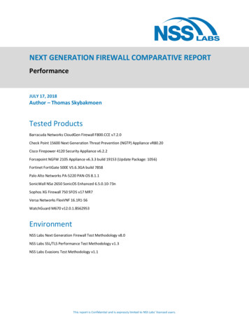
1Check the contents56789112121InstInstallatioInstallation ManInstallation Manualalla n M uation an lManualualENGLISHENGLISHENGLISHENGLISH348bandg.ban comdg.ban comdg.ban comdg.com1314101Display unit2Sun cover3Bezel trim4Power cable5Self tapping pozi screws, 4Gx1/2” (x4 for 7", x8 for 9"/12", & x12 for 16" units)6Dust caps, different sizes for NMEA 2000 (x1), Ethernet (x1 for 7"/9", x2 for 12"/16")and Sonar (x2) connectors7Dust cap for HDMI connector (12" and 16" only)8Dust cap for Video/NMEA 0183 connector9Dust cap for USB (16" only)10Document pack11Foam gasket (self adhesive)12U-bracket13Bracket knobs14Self tapping pozi screws for bracket, 14G x 1”Check the contents NSS evo3 Installation Manual
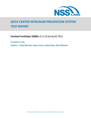
2OverviewThe unit has a built-in CHIRP/Broadband, StructureScan and ForwardScan Echosounder.The unit can network over NMEA 2000, and Ethernet allows access to data as well as controlof numerous optional devices that can provide Echosounder, radar, audio entertainment,weather and digital switching.The unit has a built-in high speed GPS receiver (10Hz) and supports Insight charts fromNavico including Insight Genesis. The system also supports charts from Navionics and C-MAPas well as content created by a variety of third party mapping providers in the AT5 format.For a full selection of available charts, visit www.gofreemarine.com, www.c-map.com orwww.navionics.com.The unit may be mounted to the vessel with the supplied mounting bracket, or panelmounted.The unit can operate on 12 V or 24 V systems.Front controls23456789101112112131Touch screen2Pages/Home - press to open the Home page for page selection and setupoptions3WheelKey - user configurable key, refer to "Configuring the WheelKey" on page 24.Default without an autopilot connected to the system: Short press: toggles between panels on split screen Long press: maximizes active panel on split screenDefault with an autopilot connected to the system: Short press: opens the autopilot controller and puts the autopilot in standbymode Long press: toggles between panels on split screen4Menu key - press to display the active panel's menu5Rotary knob - turn to zoom or scroll the menu, press to select an option6Enter key - press to select an option or to save settings7Exit key - press to exit a dialog, return to previous menu level, and clear the cursorfrom the panel8MOB - press simultaneously the Enter and Exit keys to create a MOB at thevessel's position9Arrow keys - press to activate the cursor or to move the cursorMenu operation: press to navigate through menu items and to adjust a value10Mark key - press to place waypoint at vessel position or at cursor position whencursor is active11Power key - press and hold to turn the unit ON/OFFPress once to display the System Controls dialog, additional presses to togglethrough three default dimming levelsOverview NSS evo3 Installation Manual9
12Card reader door13Dual card reader slotsRear connectionsAll units7" and 9" unitsNMEA2000VIDEOETHERNETPOWERSONAR 14 3 1 2 512" unitsETHERNETSONAR 2ETHERNETHDMIVIDEONMEA2000POWERSONAR 1SONAR 261 1 7 3 4 2 5 616" R 1SONAR 28 11 7 34 2 5 61Ethernet - connection to high bandwidth network modules2Power - 12 V or 24 V DC supply input3Video - input for video sources such as cameras, and NMEA 0183 port4NMEA 2000 - dynamic data5Sonar 1 - single channel CHIRP, 50/200 kHz conventional or HDI transducer6Sonar 2 - singel channel CHIRP, 50/200 kHz conventional, TotalScan, StructureScanor ForwardScan transducer7HDMI - video output for external monitor8USB - mouse, keyboard or mass storageCard readerUsed for inserting a microSD memory card. The memory card can be used for detailed chartdata, software updates, transfer of user data, and system backup.Ú Note: Do not download, transfer or copy files to a chart card. Doing so can damage chartinformation on the chart card.The card reader door should always be securely shut immediately after inserting or removinga card, in order to prevent possible water ingress.10Overview NSS evo3 Installation Manual
3InstallationMounting locationChoose the mounting locations carefully before you drill or cut.For overall width and height requirements, refer to "Dimensional drawings" on page 51.Do not mount any part where it can be used as a hand hold, where it might be submerged,or where it will interfere with the operation, launching, or retrieving of the boat.The unit should be mounted so that the operator can easily use the controls and clearly seethe screen.The unit has a high-contrast screen and is viewable in direct sunlight, but for best resultsinstall the unit out of direct sunlight. The chosen location should have minimal glare fromwindows or bright objects.Consider the optimum viewing angle when determining installation, refer to "Viewing angle" onpage 12.The mounting location may affect the internal GPS receiver. Test the unit in its intendedlocation to ensure satisfactory reception. An external GPS source can be added to overcomepoor reception areas.Check that it is possible to route cables to the intended mounting location.Leave sufficient clearance to connect all relevant cables.Before cutting a hole in a panel, make sure that there are no hidden electrical wires or otherparts behind the panel.Ensure that any holes cut are in a safe position and will not weaken the boat’s structure. If indoubt, consult a qualified boat builder, or marine electronics installer.Ú Note: Where flush mounted, the enclosure should be dry and well ventilated. In smallenclosures, it may be required to fit forced cooling.Warning: Inadequate ventilation and subsequent overheating of the unitmay cause unreliable operation and reduced service life. Exposing the unitto conditions that exceeds the specifications could invalidate your warranty.– refer to "Technical specifications" on page 49.Installation NSS evo3 Installation Manual11
Viewing angleThe viewing angle influences the viewability of the monitor. The recommended viewingangles relative to perpendicular are shown in the illustrations below.BA80 BB80 AA80 80 ABAOptimum viewing angleBPoor viewing angle or obstructed viewBracket mountingU-bracket mounting1. Place the bracket in the desired mounting location. Ensure that the chosen location hasenough height to accommodate the unit fitted in the bracket, and allows tilting of theunit. Also adequate space is required on both sides to allow tightening and loosening ofthe knobs.2. Mark the screw locations using the bracket as a template, and drill pilot holes. Usefasteners suited to the mounting surface material. If the material is too thin for selftappers, reinforce it, or mount the bracket with machine screws and large washers. Useonly 304 or 316 stainless steel fasteners.3. Screw down the bracket.4. Mount the unit to the bracket using the knobs. Hand tighten only. The ratchet teeth in thebracket and unit ensure a positive grip and prevent the unit from changing from thedesired angle.Flush mountingUse the separate Mouting template to flush mount the unit.Ú Note: Remember to attach the foam gasket (self adhesive ) to rear of unit before flushmounting.12Installation NSS evo3 Installation Manual
Bezel Fitment and RemovalWhen fitting bezels, ensure hook tabs on back of each bezel recess in to opposing slots onscreen frame. Once flush with front surface of screen, slide top bezel to the left, and bottombezel to the right to lock in to place.The bezel trim have been designed to be very low profile, and therefore fully conceal thelocking tabs that keep them from being accidentally disengaged from the mounting flange.To release the locking tab, gently lever the centre of the bezel trim away from the mountingflange. To remove the cover, simultaneously slide it sideways; to the right for the top bezel,and to the left for the bottom bezel.Transducer mounting locationTransducer location selection and installation are two of the most critical steps in sonarinstallation. To function properly the transducer must be in the water at all times, and in alocation that has a smooth flow of water when the boat is moving.ResearchBefore starting the installation of the transducer, check the following: Find out if the boat builder has a recommended installation location Establish the direction of rotation of the propeller(s) With the boat traveling at cruising speed, watch the water flow behind the boat to findthe area with the smoothest flow (least bubbles)Select a transducer locationThe primary aim is to stay clear of propeller and hull generated turbulence, while mountingthe transducer as close to the center of the vessel as possible.1Installation NSS evo3 Installation Manual2 34513
1Avoid mounting within 1 m (3.3’) to port (left) of propeller2Conventional clockwise propeller rotation3Avoid mounting within 7.5 cm (3“) to starboard of propeller4Best mounting location - undisturbed water flow5Planing strake - avoid mounting behind hereÚ Note: Reverse the distance guides (1 & 3) from propeller where engine is ofcounterclockwise configuration.Ú Note: Vessels with strakes or ribs on the hull can create large amounts of turbulence athigher speeds. A good transducer location on these types of boats is between the ribsclosest to the engine.Ú Note: If the transducer is not placed in a smooth flow of water, interference caused bybubbles and turbulence may show onscreen in the form of random lines or dots. Theunit could also lose bottom signal when the boat is on plane.Ú Note: Trim tabs vary in the amount of turbulence they create as they are adjusted, stayclear of these.Transducer installationFor transducer installation information, refer to separate installation instructions includedwith the transducer.14Installation NSS evo3 Installation Manual
4WiringGuidelinesDon't: make sharp bends in the cables run cables in a way that allows water to flow down into the connectors run the data cables adjacent to radar, transmitter, or large/high current carrying cables orhigh frequency signal cables. run cables so they interfere with mechanical systems run cables over sharp edges or burrsDo this: make drip and service loops use cable-tie on all cables to keep them secure solder/crimp and insulate all wiring connections if extending or shortening the cables.Extending cables should be done with suitable crimp connectors or solder and heatshrink. Keep joins as high as possible to minimize possibility of water immersion. leave room adjacent to connectors to ease plugging and unplugging of cablesWarning: Before starting the installation, be sure to turn electrical poweroff. If power is left on or turned on during the installation, fire, electricalshock, or other serious injury may occur. Be sure that the voltage of thepower supply is compatible with the unit.Warning: The positive supply wire (red) should always be connected to( ) DC with the supplied fuse or a circuit breaker (closest available to fuserating).Power connectionThe unit is designed to be powered by a 12 or 24 V DC system. It is protected against reversepolarity, under voltage and over voltage (for a limited duration).A fuse should be fitted to the positive supply; 3 A for the 7” and 9” units, and 5 A for the 12”and 16” units.4312Unit socket (male)Key1243Cable plug (female)PurposeColor1DC negativeBlack2External alarmBlue3Power controlYellow4 12/24 V DCRedPower Control connectionÚ Note: If the control unit is set to Power Slave, the unit cannot be powered down usingits own power key. Presseing and holding this key will set the unit to standby. Refer to"Power Control" on page 24.Wiring NSS evo3 Installation Manual15
The yellow Power Control wire in the power cable can either be an input that will turn on theunit when power is applied, or an output that turns on other devices when the unit ispowered on. It can be configured at the installation stage to control the power state ofdisplays and compatible devices. When commissioning the system, the unit can be set to bea Power Control Slave or Power Control Master.Power Control configuration options of the unit are: Unit turns on when power key pressed: Yellow wire not connected. Unit turns on when power source is turned on: Common red and yellow wires. Unit turns on with power key, as well as other compatible devices such as BroadbandRadar: Yellow wires connected together (Power Control Bus). (Set one or more displays tobe a Power Control Master.)Power Control unconnectedDevice will turn on and off when the power button on the front of the unit is pressed. Leavethe yellow Power Control wire disconnected and tape or heat-shrink the end to preventshorting.123 41Power cable connector to unit2Positive wire (red)3Ground wire (black)4Power control wire (yellow)5Alarm wire (blue)5Power Control to supply positive (auto on)Device will turn on immediately when power is applied. Common the yellow wire with thered wire after the fuse.Ú Note: The unit cannot be powered down by power button, but can be put in to standbymode. (The screen backlight turns off.)1243 161Power cable connector to unit2Positive wire (red)3Ground wire (black)4Power control wire (yellow)5Alarm wire (blue)Wiring NSS evo3 Installation Manual5
Power Control to ignitionDevice will turn on once ignition is turned on to start engines. Connect the yellow wire to theaccessories output of the engine key switch.Ú Note: Engine start batteries and house batteries should have a common groundconnection.1234 561Power cable connector to unit2Positive wire (red)3Ground wire (black)4Power control wire (yellow)5Alarm wire (blue)6Ignition switchPower Control master/slave busTurning on the ‘master’ device turns on connected ‘slave’ devices.POWERPOWERAB123456 7APower connection to unit on the leftBPower connection to unit on the right1Power cable connectors to units2Radar interface box3Audio entertainment device (e.g. SonicHub2)4Ground wire (black)5Positive wire (red)6Power control wire (yellow)Wiring NSS evo3 Installation Manual17
7DC power supplyIf the unit on the left (A) is turned on using the power button and is set as the Power ControlMaster, it will output voltage on the Power Control bus to power on the other unit on theright (B), the Radar Interface, and the SonicHub.If the unit on the right (B) is set to Power Control Slave, it cannot be powered down using itsown power button, but can be set to standby.If the unit on the left (A) is set to Power Control Master and is off, the unit on the right (B) canbe turned on using its own power button, but does not turn on any other devices.To turn on all network devices from either the unit on the left (A) or the unit on the right (B),both devices can be configured as Power Control Masters.Ú Note: If a unit has its power state controlled by another device (or ignition switch), itcannot be totally powered down. It can however enter a standby state to save power.External alarmThe external alarm can be a small piezo buzzer connected directly, or a horn siren connectedthrough a relay.Alarms are configured globally in the system. That is, they can be configured on any onenetworked multifunction device or instrument, and be seen, heard, and acknowledged fromall devices. Individual devices can also be configured to not sound their internal buzzer, butstill display the alarm information. For information about configuring alarms, refer to theAlarms section in the Operator Manual.For sirens that draw more than 1 Amp, use a relay.BBAACDCD BuzzerANegative power wire (black)BPositive power wire (red)CPower control wire (yellow)DAlarm wire (blue)SirenConnect an external monitorThe 12" and 16" units incorporate HDMI technology and have a HDMI output which can beconnected to an external monitor to replicate the display at a remote location. The image isshown on the external monitor at the units own native resolution, so the external monitorshould support the same resolution or be able to scale.If a monitor of different resolution is connected, a dialog is displayed at power up whichallows you to Force HDMI output to the closest resolution it can output. This may not mayprovide an optimal image on the monitor. The unit will need to restart to apply the change.Ú Note: An HDMI cable with a water tight HDMI connector should be used to connect tothe unit in exposed installations.Ú Note: While the HDMI standard does not state maximum cable length, signal may becompromised on long runs. Only use Navico or other high quality HDMI certified cables.18Wiring NSS evo3 Installation Manual
3rd party cables should be tested before installation. On runs over 10m it may berequired to add an HDMI amplifier or use HDMI-CAT6 adaptors.Ú Note: Some HDMI TV displays may apply over-scan, which will in effect crop the imagepossibly causing loss of important content. Check the display manual for an option todisable over-scan or adjust scalingNMEA 2000 backboneNMEA 2000 device connectionThe NMEA 2000 data port allows the receiving and sharing of a multitude of data fromvarious sources.1152Key542433Unit socket (male)Cable plug (female)PurposeColor1ShieldDrain2NET-S ( 12 V DC)Red3NET-C (DC negative)Black4NET-HWhite5NET-LBlueEssential network informationThe standardized physical cables/connectors for NMEA 2000 are Micro-C and Mini-C, directlyderived from the automation industries DeviceNET - Micro-C being the more commonlyused size. While most Navico products use Micro-C cabling and connectors, some products still useproprietary SimNet connectors, which are easily made compatible with adaptor cables. A network consists of a linear backbone from which drop-cables connect to NMEA 2000compliant devices. A single drop cable has a maximum length of 6 m (20 ft). The total length of all dropcables combined should not exceed 78 m (256 ft). A NMEA 2000 network, using Micro-C cabling, has a maximum cable length of 100 m (328ft), between any two points. A NMEA 2000 network needs to have a terminator at each end of the backbone. Aterminator can be one of the following:- A terminator blank plug.- A wind transducer (where the mast cable is one end of the backbone).Planning and installing a network backboneThe backbone needs to run between the locations of all products to be installed - typically ina bow to stern layout - and be no further than 6 m from a device to be connected.Choose from the following components to make up the backbone:Wiring NSS evo3 Installation Manual19
Micro-C cables: 0.6 m (2 ft), 1.8 m (6 ft), 4.5 m (15 ft), and 7.6 m (25 ft) cables. T-connector or 4-way connector. Used to connect a drop cable to the backbone. Micro-C power cable. Connect to the backbone at a position that is central to the networkload using a T-connector or 4-way connector.Power the networkThe network requires its own 12 V DC power supply protected by a 5 amp fuse or breaker.For vessels fitted with 24 V systems, use a DC-DC converter to supply 12 V.Connect power at any location in the backbone for smaller systems.For larger systems introduce power at a central point in the backbone to balance the voltagedrop of the network.Ú Note: If joining to an existing NMEA 2000 network that already has its own powersupply, do not make another power connection elsewhere in the network, and ensurethe existing network is not powered by 24 V DC.Ú Note: Do not connect the NMEA 2000 power cable to the same terminals as the enginestart batteries, autopilot computer, bow thruster or other high current devices.The following drawing demonstrates a typical small network. The backbone is made up ofdirectly interconnected T-connectors.213 12 V DC6TT41NMEA 2000 device2Connector to unit3Drop-cable, should not exceed 6 m (20 ft)4Terminators5Backbone6Power cable54NMEA 0183 device connectionThe unit has a NMEA 0183 serial port, providing both an input and an output. The port usesthe NMEA 0183 (serial balanced) standard, and can be configured in the software for differentbaud rates up to 38,400 baud.Ú Note: The connector for NMEA 0183 is labelled VIDEO on rear of unit, as the cable is dualpurpose and carries both composite video and NMEA 0183 (on seperate wires)20Wiring NSS evo3 Installation Manual
1 -1Connector to unit2Camera input 1 - red cable3Camera input 2 - green cable4NMEA 0183 RX B (orange)5NMEA 0183 RX A (green)6NMEA 0183 TX B (blue)7NMEA 0183 TX A (yellow)23RX BRX A4TX BTX A657Talkers and ListenersDo not connect multiple devices outputting data (Talkers) on to any serial input (RX) of theunit. The RS422 protocol is not intended for this type of connection, and data will becorrupted if more than one device transmits simultaneously. The output (TX) however maydrive multiple receivers (Listeners). The number of receivers is finite, and depends on thereceiving hardware. Typically three devices is possible.CZone connection to NMEA 2000When interfacing to CZone network it is recommended to use a BEP Network interfacebridge to join the two network backbones together.The CZone / NMEA 2000 Network interface bridge isolates the power of the two networks,but allows data to be freely shared between both sides.The Interface Bridge can also be used for expansion of the NMEA 2000 network, when themaximum node limit (node any device connected to network) for the network has beenreached or the maximum cable length of 150 m will be exceeded. Once an Interface Bridgehas been fitted, a further 40 nodes and additional cable length can be added.The Network Interface is available from your BEP dealer. For more information please refer tothe BEP web site www.bepmarine.com.NETWORK67 7865HG 1HWZRUN *UHHQ 1HWZRUN Network 2Network 1NETWORK INTERFACECZONENMEA2000CZONETransducer connectionThe unit has internal CHIRP, Broadband, StructureScan, TotalScan and ForwardScan sonar.There are two 9-pin transducer connectors on the rear of the unit. Traditional 50/200 Khz,CHIRP and HDI transducers can be connected to Sonar1 (Blue nut) or Sonar2 (black nut).TotalScan, StructureScan and ForwardScan must be connected to Sonar2. For connectorlocation, refer to the embossed labeling on the back of the unit or the section "Rear connections"on page 10.Ú Note: The connector attached to the transducer cable is keyed, and can only be insertedin one orientation. Once inserted, turn locking collar to secure.Wiring NSS evo3 Installation Manual21
Ú Note: A 7-pin transducer cable can be connected to a 9-pin port using a 7-pin t
18 External alarm 18 Connect an external monitor 19 NMEA 2000 backbone 20 NMEA 0183 device connection 21 CZone connection to NMEA 2000 21 Transducer connection 22 Ethernet connector . 2 Pages/Home - press to open the Home page for page selection and setup options 3 WheelKey - user configurable key, .