Transcription
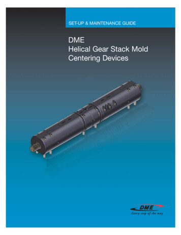
SET-UP & MAINTENANCE GUIDEDMEHelical Gear Stack MoldCentering Devices
SECTION ASafety ProceduresHelical Gear Stack MoldCentering DevicesSafety ProceduresTable of ContentsSafety Procedures. 2-4Lifting and CarryingGeneral Description .5Assembly and Initial Setup .6Contact supervision if you have any questions orare not sure about the proper procedures forlifting and carrying.On-Site Setup and Adjustment . 7-9Disassembly and Replacing Components. 10Regular Maintenance . 11Improper lifting or carrying can result in seriousinjury — especially back injury. The followingsuggestions may help you to avoid injury.Before lifting or carrying an object, determinethe weight and size by referring to such thingsas tags, shipping data, labels, marked information,or manuals. Inspect the load for nails or otherprotrusions that might cause injury. Decide if itcan be moved by one person, or several, orwhether a device such as a crane or fork liftis required. Get any necessary help beforeproceeding.If in doubt as to the size or type of lifting equipment, method, and procedures for lifting, contactDME before proceeding to lift the machine or itscomponents.Before inserting an eyebolt, be certain that boththe eyebolt and the hole have the same size andtype threads. Do not attempt to use a metricthread bolt in an English thread hole or vice versa.To attain safe working loads, at least 90% of thethreaded portion of a standard forged eyeboltmust be engaged.Questions? Call DME at 800-626-6653 (U.S.) or 800-387-6600 (Canada)2
SECTION ASafety ProceduresHelical Gear Stack MoldCentering DevicesLifting and Carrying by HandMake sure your footing is secure. Crouch as closeto the object as practical. Get a good grip on theobject. Lift slowly by straightening your legs.(Keep your back relatively straight. Your arm andleg muscles, not your back, should do the work.)Keep the load close to your body as you come up.Lift the load to the carrying position. If it isnecessary to change your direction when in theupright position, turn your body with changes offoot positions. Be careful not to twist your body.If you set the load on a bench or table, place iton the edge to allow the table to take part of theweight. Then push the load forward using the arms,or if necessary, part of the body.If you must lift the object higher than your waist,first lift the load waist high and rest it on a support(as described in the preceding paragraph). Thenchange your grip and bend your knees again togive added leg muscle power for the final lift.When carrying an object, always have a clearvision over the load. Do not try to change theload’ position, or adjust it, while you are in motion.If the load interferes with normal walking, get help.When putting the load down to the floor surfacefrom a waist high carrying position, bend theknees and with a straight back and the loadclose to the body, lower the object with thearm and leg muscles.WARNINGRegularly inspect slings, chains, hoists andother lifting devices. For frequency of inspection, refer to the Williams-Steiger OccupationalSafety and Health Act, 29 CFR 1910.184, andany instructions applicable to the equipment. Anyunsafe equipment should be properly repairedor immediately discarded. Failure to follow theseinstructions may result in serious personal injuryand/or machine damage.WARNINGCranes, hoists, slings, eyebolts, and other liftingequipment have safety-rated capacities whichshould never be exceeded. Before using any liftingequipment, make sure the equipment is adequatefor the load and application. Refer to standardsand instructions applicable to any lifting equipment you use. (For example, USAS standardB18.15, published by the American Society ofMechanical Engineers, United Engineering Center,New York, contains information concerning safelifting loads for different size eyebolts, for variousangles of lift, and for varying applications.) Failureto follow this instruction may result in seriouspersonal injury and/or machine damage.WARNINGLifting and Carrying by Mechanical DeviceUse power hoists, or other mechanical liftingand carrying devices, for heavy objects that exceedweights set forth by safety standards, or your ownphysical limitations. Objects that are bulky or hardto handle should also be lifted orcarried with the aid of mechanical devices, ratherthan by hand. This can help you avoid injury. Usehook-up methods recommended by your safetydepartment, and know the signals for safelydirecting a crane operator.There are many other safety suggestions that couldbe made. If there is a question regarding safety,ask a trained person in your company, or call theDME representative in your area.Never place any part of your body under asuspended load or move a suspended loadover any part of another person’s body. Be certainthat you have a safe spot for depositing the loadbefore lifting it. Failure to follow these instructions may result in serious personal injury and/ormachine damage.WARNINGBefore installing, removing, or maintaining thestack mold centering device in an injectionmolding machine, follow the lockout/tagoutprocedure for the injection molding machine.Failure to follow this instruction may result inserious personal injury.www.dme.net3
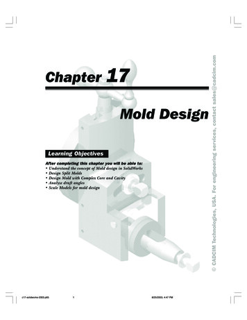
SECTION ASafety ProceduresHelical Gear Stack MoldCentering DevicesHandling the HG Stack Mold Centering DeviceThe following steps must be followed whenlifting, handling, installing, removing, operatingor maintaining the DME Helical Gear Stack MoldCentering Device. The instructions pertain to oneCentering Device assembly, and should berepeated for each assembly.There is a red Installation Strap supplied witheach assembly. During lifting, handling, installing or removing the Centering Device, one strapper assembly needs to be installed to span overthe two Bearing Housings to prevent either of thetwo Nut Housings from sliding off the Helical GearShaft, and to maintain the fixed openings betweenthe individual Nut Housing End Caps and BearingHousings.NUT HOUSING END CAPS2S2S2NUT HOUSINGNUT HOUSINGS2S1BEARING HOUSINGS7S8S7SLOTS7There are three eyebolt holes per Nut Housing,90 degrees apart from each other. Use oneeyebolt per Nut Housing (two eyebolts perassembly). Choose the best eyebolt locations(there are three to choose from) on the twoNut Housings in line so the hoisted assembly ishorizontal while installing it on the mold.WARNINGWhen the mold is closed, the gap betweenthe Bearing Housing and the Nut HousingEnd Cap is very small and can pinch orcrush anything that is in between them.Do not leave tools, screws, etc. betweenthese surfaces. Failure to follow thisinstruction may result in serious personalinjury and/or machine damage.Use the four Alignment Rods that are shippedwith your order when mounting the assembly tothe mold. The Alignment Rods are approximately300mm long, and they are for properly prealigning the assembly when it approaches the mold. Ifthe installation takes place while the mold is in theinjection molding machine, the 300mm AlignmentRods may be too long for the available space.In this case, cut the rods to shorter lengths, sothere is enough room to lower the CenteringDevice, and the corresponding mounting holescan align to the Alignment Rods screwed inthe mold, one rod per Nut Housing andBearing Housing.WARNINGIf this stack mold centering device is installedon an injection molding machine with amotion/no motion key switch, all pinchingand shearing points in the mold area must beguarded (ref: ANSI B151.1-1997, clause 7.8).Failure to follow this instruction may result inserious personal injury.Screw the four Alignment Rods into thetapped holes with tubular dowel bores in line.See Steps 4 and 5 in the On-Site Setup andAdjustment section.The hoisted assembly needs to stay in horizontalorientation during the whole process.Questions? Call DME at 800-626-6653 (U.S.) or 800-387-6600 (Canada)4
SECTION BGeneral DescriptionHelical Gear Stack MoldCentering DevicesGeneral DescriptionThe function of the DME Helical Gear StackMold Centering Device is to provide equal andsynchronized parting line openings for stackmolds. The stack mold can be a standard,spin-stack or other type where centering ofthe center portion of the stack mold or centerplaten of a Dual Mold Carrier between thestationary and moving platen is required.The main functional components in anassembly are a double-helical Gear Shaftwith a left hand thread on one end of theshaft, a right hand thread on the other, aswell as two mating Nuts that fit on thecorresponding threads.The Gear Shaft is retained by a pair of TaperedRoller Bearings in the Bearing Housings, andthe Nuts are held in the Nut Housings.A stack mold usually needs two or four assemblies to operate. The DME Helical Gear StackMold Centering Device is adjustable, whichmeans that the device can be adjusted to compensate for differences between the moving and stationary side stackheights.www.dme.net5
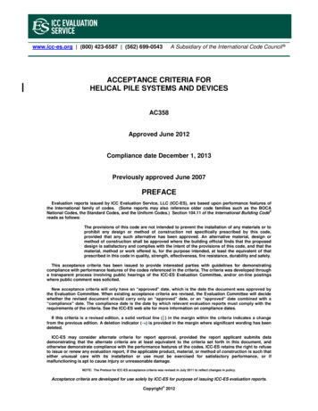
SECTION CAssembly and Initial SetupHelical Gear Stack MoldCentering DevicesAssembly and Initial SetupThe Bearing Housings and Nut Housings arepre-assembled at DME assuming equalmoving and stationary side stack heights, andsymmetric mounting configurations.The outer ring of the Tapered Roller Bearing isground to be within the required tolerance, andDME maintains a record of the final S7 S7S7S5S5S8S5S5S2S2After installation, the Bearing Housing is filledwith grease for proper lubrication.TD2TD1TD1Questions? Call DME at 800-626-6653 (U.S.) or 800-387-6600 (Canada)6TD2
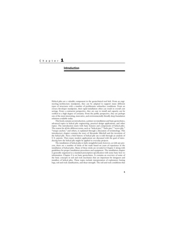
SECTION DOn-Site Setup and AdjustmentHelical Gear Stack MoldCentering DevicesOn-Site Setup and AdjustmentThe final adjustment needs to be donewhen the HGSM devices are first mountedon the mold. One assembly contains twoNut Housings with Nuts that are usuallymounted on the two “B” halves, and theBearing Housings with the double-endedHelical Gear Shaft that is mounted on thefloating center portion of the mold.The sequence of steps is as follows:BEARING HOUSINGS6S2S7S6S8S2Step 1Note: The gaps between each NutHousing End Cap and the BearingHousing are usually not sufficientlyequal to mount and use the CenteringDevices without final adjustment. Someadjustment of the gaps between the NutHousing and Bearing Housing to allowproper mounting should be expected.S7S7S2S1S2S3S1S6S3SLOTS3TD1NUT HOUSINGS1NUT HOUSING END CAPTD1Step 2On each assembly, make sure that onone Nut Housing, all four S6 and three S7screws are tightened to the prescribedtorque (see assembly drawing). Thesescrews should remain tight during theadjustment process.BEARING HOUSINGOn the other Nut Housing of eachassembly, loosen the four S6 screwsand remove the three S7 screws. Insertone of the S7 screws into the S8 jackingscrew hole between the first and secondS7 screw position from the Nut HousingEnd Cap. Turn the S7 screw until the Sloton the side of the Nut Housing slightlyopens, so the Nut can freely rotate butis still retained by the End Cap.S6S7S6S7S8S7S2S1NUT HOUSINGS6SLOTStep 3Open the mold to have approximately50mm parting line opening on each side.NUT HOUSING END CAPwww.dme.net7
SECTION DOn-Site Setup and AdjustmentHelical Gear Stack MoldCentering DevicesStep 4While the Helical Gear Stack Moldis engaged in the Nuts, mount theBearing Housings and theNut Housings (which already havetightened S6 and S7 screws)onto the mold by using fourS2 screws and four TD1 tubulardowels per Bearing Housing,and four S5 screws and twoTD2 tubular dowels per NutHousing. See “Handling theHelical Gear Stack Mold CenteringDevice” for usage of the supplied Alignment Rods to align theassembly during mounting tothe mold.Step 5Pull or push the other Nut Housingwith the loose S6 screws and one S7jacking screw in the direction of theHelical Gear Stack Mold until its mountingholes align with the mounting holesof the corresponding “B” half.(Note: The Nut now should freelyrotate to self-align to the properorientation.) Mount this Nut Housingon the mold using four S5 screwsand two TD2 tubular 5S5S2TD2S8S7 S7S2TD1S7TD1TD2NUT HOUSING END CAPS2S2S2NUT HOUSINGS2NUT HOUSINGS1S7BEARING HOUSINGS8S7SLOTS7Step 6Repeat the previous steps withall assemblies.Step 7Close the mold, remove the S7 screwused as a jacking screw, and insert allthree S7 screws into their counterbore,then tighten them to the prescribedtorque per each assembly.S5BEARING HOUSINGS2S2S7S8S7S7S1S1TD1TD1NUT HOUSINGSLOTNUT HOUSING END CAPQuestions? Call DME at 800-626-6653 (U.S.) or 800-387-6600 (Canada)8
SECTION DOn-Site Setup and AdjustmentHelical Gear Stack MoldCentering DevicesStep 8Open the mold again slowly to approximately50mm per parting line, so the loose S6screws are accessible. Tighten the S6 screwsto the prescribed torque.BEARING HOUSINGS6S2Step 9Dry cycle the mold while observing themaximum parting line opening shown inthe drawing. The Helical Gear Stack Molddisengages from the Nylon Nut, andbreakage may occur if the noted maximumparting line opening is exceeded. Duringdry cycling of the mold, pay close attentionwhether the mold operates smoothly andwithout any cocking. Repeat the previouslydescribed setup procedure if it is needed.Notify DME if any problem persists.S7S6S8S2S7S2S1S2S3S7S1S6S3SLOTS3TD1NUT HOUSINGS1NUT HOUSING END CAPTD1Step 10DME provides three Grease Nipples oneach Bearing Housing: front, top andbottom, so at least one of them should beeasily accessible even when the CenteringDevice is installed behind the tie bars orother equipment.www.dme.net9
SECTION EDisassembly and Replacing ComponentsHelical Gear Stack MoldCentering DevicesDisassembly and Replacing Componentsinstall the Nut Housing End Cap, but leave theS6 screws only hand tight. Leave the S7 screwin the S8 jacking position.The Helical Gear Stack Mold Centering Device hascomponents that wear during usage. The frequency between replacing these components dependson the number of cycles, the level of maintenance,mold alignment, and other environmental factorssuch as humidity and contamination.Follow the steps from Step 3 through Step 10 ofSection D to mount and set up the proper timingof the Helical Gear Stack Mold Centering Devices.Replacing the Nylon Nuts: The Nylon Nutsare designed to be the wear item in the HelicalGear Stack Mold Centering Device. Slack betweenthe parting line openings is a visual indicator ofworn Nylon Nuts.Replacing the Taper Roller Bearing:If the Taper Roller Bearing needs to be replaced,first contact DME to get the final, no-preloadthickness of the Bearing, and grind the thickerside of the outer ring so the assembled Bearinghas the given thickness.In addition to the wear items, the Nylon Nuts arealso designed to be the preferred failure point inthe case of catastrophic failure or seizing duringmold operation. For these reasons, DMErecommends keeping at least one full set ofNylon Nuts as spare parts.Unmount the assembly from the mold. Pull theBearing Housings off the Helical Gear Shaft.Remove the S1 screws, and using the four M6tapped jacking screw holes per side in theBearing Housing marked S3 (locations are shownon pages 7 and 9), insert and turn four M6 screwsper side until one Bearing Housing is pushed offthe outer ring of the Taper Roller Bearing. Do thesame with the other side, too.The Nylon Nuts may be replaced while themold remains in the press, but it’s necessaryto unmount the entire Helical Gear Stack MoldCentering Device assembly with the worn NylonNut from the mold, and do the replacement onthe bench.Using the four Slots of the shoulder of the HelicalGear shaft, push the inner rings of the TaperedRoller Bearings off the shaft.DME recommends replacing all Nylon Nuts atthe same time, because the amount of wear isusually similar on all of them, and downtimecan be spared if all replacements take placeat the same time.To remove the worn Nylon Nut, remove thefour S6 screws that hold the Nut Housing EndCap. Remove the three S7 screws, insert oneof them into the S8 jacking hole, and turn ituntil the gap on the side of the Nut Housingopens slightly, so the Nylon Nut is free fromthe frictional force and can move freely. Pullthe Nut Housing while the Helical Gear Shaftdoes not turn, so the Nut can be pulled out ofthe Nut Housing.BEARING HOUSINGS7S7S8S2S7S6S6S2S1S1S6NUT HOUSINGAfter cleaning the inside of the Nut Housingof any contamination, the new Nylon Nut canbe installed while the one S7 screw is stillkeeping the Slot slightly open. When theNylon Nut bottoms out in the Nut Housing,S1SLOTNUT HOUSING END CAPQuestions? Call DME at 800-626-6653 (U.S.) or 800-387-6600 (Canada)10
SECTION FRegular MaintenanceHelical Gear Stack MoldCentering DevicesRegular MaintenanceThere are two areas that need to beregularly maintained:1. Taper Roller BearingsThere are two Bearing Housings perassembly. They are screwed together withthe two Taper Roller Bearings inside thatcapture the shoulder of the Helical GearShaft. Once a week, use a grease gun topush one unit of grease into each of theBearing Housings through one of thethree Grease Nipples per Bearing Housing.Do the same for all of the assemblies.Note: Each assembly has two BearingHousings screwed together, so two nipplesper assembly need to be used to greasethe Taper Roller Bearings.2. Helical Gear Shaft and NutThe contamination that can come from thesurrounding equipment, machines, tools,etc. (such as grease, oil, or residue from theinserted Nylon Nut), could stick to the Shaftand the Nut. This contamination could betransferred to the plastic parts and it canalso accelerate the natural wear process.To prevent or slow these processes, cleanthe surfaces at regular intervals.www.dme.net11
World HeadquartersDME Company LLC29111 Stephenson HighwayMadison Heights, MI 48071800-626-6653 toll-free tel248-398-6000 tel888-808-4363 toll-free faxwww.dme.net websales@dme.net e-mailLitho in U.S.A.DME of Canada Ltd.6210 Northwest DriveMississauga, OntarioCanada L4V 1J6800-387-6600 toll-free tel905-677-6370 tel800-461-9965 toll-free faxdme canada@dme.net e-mailDME EuropeDME Belgium C.V.B.A.Industriepark NoordB-2800 MechelenBelgium32-15-215011 tel32-15-218235 faxsales@dmeeu.com e-mailHGSMCD D&A-5/10
DME Helical Gear Stack Mold Centering Devices. Helical Gear Stack Mold Centering Devices SECTION A Safety Procedures 2 Questions? Call DME at 800-626-6653 (U.S.) or 800-387-6600 (Canada) . components. Before inserting an eyebolt, be certain that both the eyebolt and the hole have the same size and type threads. Do not attempt to use a metric